Chapter 16. Deploying Gatekeepers
A gatekeeper is an H.323 device that can provide services such as address translation, admission control, bandwidth management, and centralized dial plan management to facilitate network scalability. Gatekeepers can provide these services for H.323 terminals, gateways, and multipoint control unit (MCU). Cisco CallManager can also take advantage of gatekeeper services.
The Cisco IOS gatekeeper feature is supported on the Cisco 2600, 3600, 3700, 2800, 3800, and 7200 families of routers using the appropriate Cisco IOS and feature license.
Although gatekeeper usage is optional, a gatekeeper can provide many benefits to improve scalability and management. It this chapter, you will learn about the benefits that gatekeepers can provide in an IP Telephony network.
This chapter helps you to do the following:
• Comprehend the terminology used when discussing gatekeepers
• Understand gatekeeper mandatory and optional functions that you can use in an IP Telephony network
• Know the protocols and signaling methods that gatekeepers use
• Be able to select appropriate hardware and software to use for gatekeeper deployments
• Learn the various deployment models that you can use to enhance scalability of a gatekeeper-controlled network
• Discover how CallManager interacts with an H.323 gatekeeper
Gatekeeper Functionality
The concept of a zone is used to define the group of H.323 devices that an individual gatekeeper controls. That is, the devices that belong to the zone register with the controlling gatekeeper. Zones can cross subnets, and a gatekeeper can manage devices in one or more subnets. Up to 100 zones can be registered to an individual gatekeeper.
Prior to H.323 Version 2, only one gatekeeper could be active in a zone at a time. H.323 Version 2 introduced the concept of alternate gatekeepers. Implementing the alternate gatekeeper feature allows multiple gatekeepers to control one zone. This helps to provide redundancy and load sharing for large installations. The gateway must also support the alternate gatekeeper to use this feature.
Figure 16-1 is an example of two gatekeepers controlling devices in two separate zones. Notice that communication and signaling can cross between the zones.
Figure 16-1. Multiple Gatekeepers and Zones
The following are services for voice calls that the gatekeeper can provide:
• Address resolution—H.323 IDs and E.164 telephone numbers can be resolved to an IP address for the destination gateway. This is similar to the way Domain Name Services (DNS) resolve fully qualified domain names to their associated IP addresses.
• Admission control—Gateways or endpoints that are initiating a call request admission into the H.323 network. For example, a gateway can request to place a phone call, and the gateway then presents the called number to the gatekeeper. If the gatekeeper can resolve the number, security requirements are met, and bandwidth is available, the gatekeeper permits the call to be placed.
The gatekeeper can track bandwidth that active calls use both within and between zones. You can configure the maximum bandwidth available. When you place a call, the bandwidth used is subtracted from the maximum. If bandwidth is insufficient to place the call, the call is rejected. When a call terminates, the bandwidth for that call is returned to the available pool.
• Bandwidth management—Bandwidth is initially managed during admission control. If the bandwidth requirements change during a call, the gateway makes a bandwidth request of the gatekeeper. If the new bandwidth is available, the request is accepted; otherwise, it is rejected.
• Zone management—The gatekeeper controls gateway registration within the controlled zone. Gateways make registration requests to the gatekeeper. The gatekeeper either allows the gateway to register or rejects the request.
• Call authorization—This option allows a gatekeeper to control access to and from certain gateways or endpoints. You can do this using authentication, authorization, and accounting (AAA) services that Cisco IOS provides in conjunction with a RADIUS server.
Gatekeeper Signaling
Cisco IOS gatekeepers use a variety of signaling methods to provide control capabilities, redundancy, and extensibility of the H.323 network. These include the H.323 Registration, Admission, and Status Protocol (RAS), the Gatekeeper Update Protocol (GUP), and the Gatekeeper Transaction Messaging Protocol (GKTMP).
RAS Signaling
Gatekeepers are H.323 devices that use the RAS protocol to communicate with Cisco voice gateways. RAS is a subset of the H.225 signaling protocol.
Call control and call setup are also done using H.225 signaling. If the call control/call setup H.225 messages go directly between gateways (not through the gatekeeper), it is known as direct endpoint signaling. Some gatekeeper implementations support gatekeeper-routed call signaling (GKRCS). With GKRCS, all H.225 signaling (RAS and call control/call setup) is passed from the gateway to the gatekeeper. No H.225 messages are sent directly between gateways.
Note
Cisco gatekeeper implementations do not support GKRCS. Only direct endpoint signaling is supported.
H.245 signaling is another subset of H.323 that is used for media control. H.245 flows directly between gateways to facilitate setup of the media stream.
Figure 16-2 shows the H.323 signaling and media flow for a typical voice call.
Figure 16-2. H.323 Signaling Flow

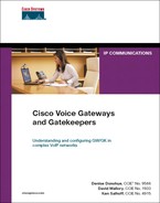
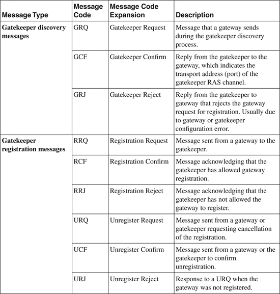
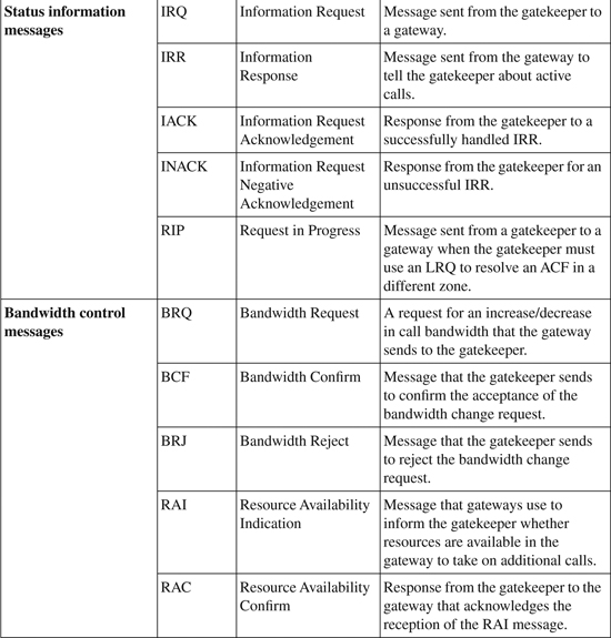
H.225 RAS uses defined message types to communicate between the gatekeeper and the gateway. Table 16-1 lists the specific RAS messages.
Table 16-1. H.225 RAS Messages
Gatekeeper Discovery Process
A gateway will send a GRQ RAS message when trying to identify the gatekeeper for its zone. An H.323 gateway can discover its zone gatekeeper in two ways:
• Unicast discovery—This method requires that the IP address of the gatekeeper is configured in the gateway. The gateway immediately sends a GRQ using User Datagram Protocol (UDP) port 1718. The gatekeeper either responds with a GCF or a GRJ.
• Multicast discovery—This method enables a gateway to automatically discover its gatekeeper through a multicast GRQ message sent on multicast address 224.0.1.41. Using this method has less administrative overhead because the gateways do not have to be statically configured with the gatekeeper address. A gatekeeper can be configured to respond only to certain subnets.
If multiple gatekeepers are on the network, using multicast discovery might require you to implement an IP network design such that a gateway or other endpoint can reach only the correct gatekeeper using the multicast message, or use unicast gatekeeper discovery. If multiple gatekeepers are reachable, you will not know which gatekeeper is discovered by the multicast, and unpredictable behavior can result.
If a gatekeeper is not available, the gateway attempts to rediscover one. If a gateway discovers that its gatekeeper has gone off-line, it no longer accepts new calls; however, calls in progress are not affected.
Because of the criticality of the gatekeeper in the network, most users implement redundancy to minimize the possibility of a network outage because of a failure. Methods of implementing redundancy are discussed later in this chapter.
Figure 16-3 illustrates both methods of gatekeeper discovery.
Figure 16-3. Gatekeeper Discovery

H.323 Call Flows Using Gatekeepers
Figure 16-4 shows an example of a call flow between two gateways within the same zone when a gatekeeper is used for E.164 number resolution. Both sides must successfully request admission before the call can be completed. Both gateways send IRRs to the gatekeeper after the call setup is complete and again when the call is terminated. The IRR messages are especially important if you are using the gatekeeper to collect call detail records (CDR) or for call admission control (CAC). When the IRR is received at the end of a call, the CDR is logged and the bandwidth that is used by that call is freed.
Figure 16-4. H.323 Intrazone Call Setup
The process for setting up an intrazone H.323 call is as follows:
1. A New York phone dials 208-555-0100 to reach Boise.
2. A New York gateway sends an ARQ, asking permission to call Boise.
3. The gatekeeper does a lookup and finds that the Boise gateway is registered. The gatekeeper returns an ACF to the New York gateway with the IP address of Boise.
4. The New York gateway sends an H.225 (Q.931) call setup message to the Boise gateway, including the phone number.
5. The Boise gateway sends an ARQ to the gatekeeper requesting permission to answer the call.
6. The gatekeeper returns an ACF message, which includes the IP address of the New York gateway.
7. The Boise gateway sets up a plain old telephone service (POTS) call to the phone at 208-555-0100.
8. When the phone is answered, the Boise gateway sends an H.225 (Q.931) Connect message to the New York gateway.
9. Both gateways send an IRR to the gatekeeper after the call setup is complete.
Figure 16-5 shows an example of the signaling flow for the same call with each of the gateways belonging to a different gatekeeper zone.
Figure 16-5. H.323 Interzone Call Setup
The process for setting up an interzone H.323 call is as follows:
1. A New York phone calls the Boise phone at 208-555-0100.
2. A New York gateway sends Gatekeeper A (the gatekeeper where the New York gateway is registered) an ARQ, requesting permission to make the call.
3. Gatekeeper A does not find a match for the requested phone number; however, it does a prefix lookup and finds Gatekeeper B. Gatekeeper A sends an LRQ to Gatekeeper B. At the same time, Gatekeeper A sends an RIP message to the New York gateway.
4. Gatekeeper B finds a match on the number with the Boise gateway. Gatekeeper B returns an LCF to Gatekeeper A with the IP address of Boise.
5. Gatekeeper A sends an ACF to the New York gateway with the IP address of Boise.
6. The New York gateway sends an H.225 (Q.931) call setup request to the Boise gateway, including the 208-555-0100 called phone number.
7. The Boise gateway sends Gatekeeper B an ARQ requesting permission to complete the call.
8. Gatekeeper B returns an ACF that includes the IP address of the New York gateway.
9. The Boise gateway sets up a POTS call to the phone at 208-555-0100.
10. When the phone is answered, the Boise gateway sends an H.225 (Q.931) Connect message to the New York gateway.
11. Both gateways send an IRR to the gatekeeper after the call setup is complete.
Gatekeeper Update Protocol
Gatekeeper clustering or alternate gatekeepers are methods of providing gatekeeper redundancy that utilizes the GUP protocol. GUP messages are used both to establish the initial connections between members of the cluster and to exchange status information between cluster members.
GUP uses versions of RAS gatekeeper discovery messages that include nonstandard fields for communications.
When the cluster is first established, the gatekeeper opens and maintains a TCP connection to the other members of the cluster (the alternate gatekeepers). The gatekeeper announces its presence by sending a GRQ message containing nonstandard data; then it flags it as an announcement. The announcement also carries information about bandwidth utilization for a zone. This allows the alternate gatekeepers to manage the bandwidth for a zone even though they are separate devices.
GUP GRQ messages can be one of the following formats: announcementIndication, announcementReject, registrationIndication, unregistrationIndication, or resourceIndication.
GUP announcements are sent every 30 seconds by default. Cluster members assume that a gatekeeper has failed if nothing is heard from that gatekeeper for six consecutive announcement periods or if the TCP connection is lost.
When a gateway registers/unregisters with a gatekeeper in a cluster, that gatekeeper uses the registrationIndication/ unregistrationIndication message to update all other gatekeepers in that cluster.
If a gateway reports a resource change using an RAI message to a gatekeeper in a cluster, that gatekeeper reports the change to all alternate gatekeepers in the cluster using the GUP resourceIndication message.
GUP messages allow all the gatekeepers in a cluster to have knowledge about the registration status, bandwidth, active calls, and resource status for every gateway in the zone.
Gatekeeper Transaction Message Protocol
Although the Cisco gatekeeper provides a rich set of functions to assist in controlling an H.323 network, additional functionality might be needed sometimes. Examples might include requirements for additional authentication, the need to implement additional specific policy controls, the desire to use Internet call waiting, or any other customized application logic used to direct call setup and control.
GKTMP was developed along with the gatekeeper application programming interface (API) to facilitate communication between the gatekeeper and an external application.
GKTMP is based on RAS and provides a set of messages that can be used to exchange information between the Cisco gatekeeper and an external application over a TCP connection.
Through the use of GKTMP and the gatekeeper API, organizations can add new functionality to the gatekeeper by using external applications. This can be done transparently to the H.323 gateways.
You can find more information about GKTMP and the gatekeeper API in the Cisco Gatekeeper External Interface Reference available at Cisco.com.
E.164 Number Resolution
Cisco gatekeepers group gateways into logical zones and perform call routing between them. Cisco gatekeepers handle call routing among gateways in the H.323 network and provide centralized dial plan administration. Without a Cisco gatekeeper, Voice over IP (VoIP) dial peers would need to be configured in every originating gateway for each possible termination gateway within the network. These would need to point to the specific IP address (or DNS name) for each terminating gateway. With a Cisco gatekeeper, gateways query the gatekeeper when trying to establish VoIP calls with a remote VoIP gateway.
For example, when a call request is made, the gateway determines whether to send it to a connected trunk (public switched telephone network [PSTN] or PBX) or to an IP destination based on the configured dial plan. In the case of an IP destination, the gateway queries the Cisco gatekeeper to select the best gateway.
ARQ and LRQ are the two RAS messages that initiate call routing. Gatekeepers receive ARQ messages from a gateway registered to a local zone either as a result of an outbound call initiation from the gateway or to request permission to accept an incoming call.
LRQ messages are passed between different gatekeepers and are used to route calls from a local to a remote zone (interzone routing).
Zone Prefixes
A zone prefix is the part of a called number that identifies the destination zone (local or remote) for the call. Zone prefixes can be based on area codes and local exchanges, or any characteristic of the called number prefix that makes it unique to the call routing domain. If the network is supporting extension dialing between locations, the zone prefix might be the first number of the extension or a location code used to identify a remote site. Whatever prefix is selected must be unique so that the gatekeeper can select the proper destination zone for the call.
In Example 16-1, calls beginning with 212 are routed to the NY local zone, and calls beginning with 208 are routed to the BO local zone.
gatekeeper
zone local NY cisco.com 10.1.5.1 1719
zone local BO cisco.com
zone prefix NY 212…….
zone prefix BO 208…….
You can configure zone prefixes manually, as shown in the example. Cisco IOS Versions 12.1T and later support an H.323 Version 2 enhancement that allows automatic creation of zone prefixes for devices with assigned E.164 addresses that are attached to the gateway, such as phones connected to Foreign Exchange Station (FXS) ports. Cisco IOS Versions 12.2.15T and later support an H.323 Version 4 feature that allows gateways to dynamically register prefixes that are assigned to POTS dial peers.
Multiple prefixes can exist for a single local zone, and a gateway belonging to multiple zone prefixes might register to the gatekeeper.
Prefixes can have overlapping number ranges. If prefixes overlap, the prefix that has the longest match is used. For example, if you have defined a prefix for the NY gateway as “212” and one for the Boise gateway as “2..”, the prefixes will overlap. In this case, both prefixes begin with a “2,” and numbers beginning with “212” could match either prefix. However, the longest match is to the NY prefix of “212,” and it will always be selected. Conversely, a “212” number will never match the “2” prefix, even if the NY gateway is not registered to the gatekeeper. In this case, the “212” prefix will still be matched, but the address of the gateway will be unknown, so an ARJ will be sent. An exception to this is if the prefixes are dynamically learned from the gateways. In this case, if the NY gateway is unregistered, the “212” prefix will be deleted, and the “2..” prefix will be matched.
It is important to understand how prefix matching is done so that you can properly design a gatekeeper-controlled dial plan.
Technology Prefixes
A technology prefix is an optional H.323 feature that the Cisco gatekeeper uses to group gateways by type (such as voice or video) or class or to define a pool of gateways.
When you are routing a call, you use the technology prefix when no registered E.164 address matches the called number.
To use technology prefixes, you must do two things:
• Assign the gateway a technology prefix—You can do this on the gateway so that the prefix is registered with the gatekeeper as part of the RRQ. You can also configure it statically on the gatekeeper so that the technology prefix is associated with the gateway IP address.
This identifies the technology (type, class, or pool) that the gatekeeper associates with this particular gateway when performing call routing.
• Prepend a technology prefix to the called number sent in the ARQ to the gatekeeper—You can do this on the H.323 VoIP dial-peer configuration within the gateways. The gatekeeper attempts to match the appended technology prefix with the prefix of a registered gateway to identify the destination zone for routing.
The technology prefix is stripped from the called number when the gateway attempts to match a zone prefix. However, the full number with the technology prefix is delivered to the destination gateway. Be sure that POTS dial-peers are updated to handle this properly.
You can also configure a default technology prefix in the gatekeeper. Registered gateways with the matching technology prefix are used as default for routing call addresses that are unresolved. Some H.323 endpoints do not support coding a technology prefix. The default technology that is defined on the gatekeeper is also used for those devices.
You can also configure hop-offs on the gatekeeper based on technology prefix. A hop-off is used to override the zone prefix and force the call to be routed to the specified hop-off zone regardless of the called number zone prefix.
Technology prefixes are most often used in multimedia H.323 networks to identify the type of call as either video or voice. They are also used in large networks where multiple gateways are pooled to provide greater capacity and redundancy.
Gatekeeper Call Routing Process
Figure 16-6 illustrates the overall process that the Cisco gatekeeper uses to try to route a call. The Cisco multiservice IP-to-IP gateway (IPIPGW) feature introduces gatekeeper via-zones. The sections of the diagram that are labeled “Via-Zone Processing” refer to a separate decision tree process that the via-zone-enabled gatekeepers use in an IPIPGW environment. This concept is discussed in Chapter 18, “Cisco Multiservice IP-to-IP Gateway.”
Figure 16-6. Gatekeeper Call Routing Decision Tree
Call Admission Control
Call admission control (CAC) is important to the successful implementation of an IP voice network. If the amount of bandwidth required to support active calls exceeds that which is available on the network, voice quality suffers for all calls. Several mechanisms are available to provide CAC services. The methods selected depend heavily on the overall design of the network. Available CAC mechanisms include CallManager location-based CAC and Resource Reservation Protocol (RSVP). You can also configure the Cisco gatekeeper to provide CAC on an H.323 network.
The gatekeeper maintains a record of all active calls so that it can manage the bandwidth in a zone. When calculating whether enough bandwidth is available to accept a call ARQ, the gatekeeper uses the following formula:
Available bandwidth = (Total allocated bandwidth) × (Bandwidth used locally) × (Bandwidth used by all alternates)
If the available bandwidth is sufficient for the call, an ACF is returned; otherwise, an ARJ is sent.
When you configure bandwidth control, you need to consider the coder/decoder (codec) in use for the call, Layer 2 encapsulation, and compression techniques (such as RTP header compression) that are in use.
You can request bandwidth changes if necessary after call setup. As of Cisco IOS Release 12.2(2)XA and later, Cisco voice gateways can request a bandwidth change if the codec in use changes. Prior to this release, calls were always reported to require a bandwidth of 64 Kb, the unidirectional bandwidth for a G.711 codec. Cisco IOS Release 12.2(2)XA and later conform to H.323 Version 3 specification, and the reported bandwidth is bidirectional. Initially, 128 Kb of bandwidth is reserved for the call using a G.711 codec, or 16 Kb for a call using the G.729 codec. If a change in bandwidth is required during the call, the gateway notifies the gatekeeper of a bandwidth change using a BRQ message.
You handle Cisco CallManager CAC for voice calls in the same way that you handle CAC for Cisco IOS voice gateways. A difference is that CallManager also can place video calls. When you are designing a CAC implementation that includes video endpoints such as those on CallManager, you must also take the video bandwidth into account. With CallManager, the bandwidth requested from the gatekeeper for a video call is two times the bit rate of the call—a 384-Kb video call counts as 768 Kb, a 512-Kb video call counts as 1024 Kb, and so on. Besides limiting the total available bandwidth, you can limit the maximum bandwidth that a single call can request. This is useful when video is also present on the network. CallManager is discussed more fully later in this chapter.
You can configure the following types of zone bandwidth controls on a Cisco gatekeeper:
• The maximum bandwidth for all traffic between the local zone and a specified remote zone. You can set up this limitation individually for multiple remote zones.
• The maximum bandwidth for all traffic from a zone to all remote zones.
• Perform a check of the destination gateway bandwidth before responding to the ARQ (Cisco IOS Release 12.3(1) and later).
• The maximum bandwidth for a single session within the local zone. As mentioned, this is typically used for video traffic and not voice.
It is important to consider the network topology when planning gatekeeper-controlled CAC implementations.
Figure 16-7 shows an example of an implementation over a simple network topology. In this example, the WAN connection between New York and Boise can only support two calls because of bandwidth limitations. If you are using the G.729 codec, you could configure the gatekeeper to limit the bandwidth to 32 kbps. The first two calls would complete successfully. The third call would exceed the bandwidth limitation and be denied.
Figure 16-7. Simple CAC Implementation
Unfortunately, most networks are not as simple as the one shown in Figure 16-7. A more complex scenario would be to have separate gateways at multiple locations with differing WAN bandwidths between locations. In our sample network, the New York location can handle 24 simultaneous calls; the Boise location can handle two calls; the Leeds location can handle four simultaneous calls.
You could set the bandwidth limits based on the site with the least capacity within the zone. In this example, you would set the gatekeeper to allow only two concurrent calls, based on the capacity at the Boise location. This would ensure good voice quality, but you would place inefficient limits on the other locations that can handle more calls.
A better approach would be to set up multiple gatekeeper zones. If you set up a single zone per site, you could have much more control over the bandwidth allocation. Figure 16-8 depicts the interzone bandwidth limits.
Figure 16-8. Complex Multizone CAC Implementation
The configuration shown limits the traffic in various ways:
• Between New York and Leeds to four calls maximum
• Between New York and Boise to two calls maximum
• Between Leeds and Boise to two calls maximum
In this configuration, you are ensuring good voice quality and making the best use of the available bandwidth at each site. The gatekeepers shown are logical, not physical. You can control the zones from a single physical gatekeeper.
As you can see from this example, when you are designing gatekeeper-based CAC on an H.323 network, it is important to consider all aspects of the network topology: paths to destination; bandwidth to destination; and the number of gateways that can reach the destination. The gatekeeper is not aware of the topology of the network. Decisions about whether or not to admit a call are based solely on static configurations and calculations of available versus used bandwidth. For gatekeeper CAC to function correctly, the network must be laid out in a hub-and-spoke design. Alternate paths are not taken into account. Other CAC mechanisms such as CallManager location-based CAC have the same limitations. Although using these methods is much better than not implementing CAC, RSVP can make dynamic CAC decisions based on currently available bandwidth along the selected path to a destination. If RSVP is available on your network, it can be a better choice for implementation of CAC.
Gatekeeper Deployment Models
Without the use of a gatekeeper, as the number of gateways in an H.323 network increases, the effort to manage the dial plan grows exponentially. For each gateway, you must specifically code VoIP dial-peers pointing to the IP addresses (or DNS names) of every destination gateway that can be reached from that originating gateway.
When a gatekeeper is used, the dial plan is vastly simplified. Only the local trunk connections need to be defined in the gateways using POTS dial peers. The E.164 addresses to reach these local trunks are then registered with the gatekeeper. You can do this manually by coding zone prefix statements in the gatekeeper, or the gatekeeper can dynamically learn them from the gateway when it registers.
In this configuration, the gateway is only aware of local trunk connections and the gatekeeper. It has no direct knowledge of any of the other gateways in the network. When a call comes into the gateway, one of two things happens:
• A POTS dial peer is matched, and the call goes out a local trunk connection.
• The gateway issues an ARQ to the gatekeeper to find the destination for the call.
Figure 16-9 illustrates the effect of this simplification on even a small network.
Figure 16-9. Dial Plan Simplification Using a Gatekeeper

Redundancy
A gatekeeper is a critical network component. It is responsible for most or all of the call routing, bandwidth management, and CAC. Because the gatekeeper centrally controls the dial plan, a failure can cause disruptions across the entire network under its control. Because of this criticality, it is advisable to implement gatekeeper redundancy to reduce the possibility of service interruptions.
Several options are available to provide redundancy in a gatekeeper-controlled network:
• Gateway dial peers—Gateways use dial peers that are coded with RAS as the session target to communicate with the gatekeeper. You can code additional VoIP dial peers in the gateway with a lower priority than the RAS dial peer. These lower-priority dial peers have as session targets the IP addresses of the gateways to which they can send calls.
If the gatekeeper becomes unreachable, the RAS dial peer becomes inactive. At that point, the gateway begins using the lower-priority dial peers to resolve destination addresses.
Although this might work for smaller networks, the added administrative overhead for coding and maintaining the redundant dial peers removes much of the advantage of using a gatekeeper for centralized dial plan management.
• Hot Standby Routing Protocol (HSRP)—Another method of gatekeeper redundancy is the use of HSRP. HSRP has been available for some time in Cisco IOS. Guidelines and caveats for implementing HSRP on a Cisco IOS gatekeeper are as follows:
—Only one gatekeeper is active at any given time.
—The standby gatekeeper does not process calls unless the primary gatekeeper fails.
—No load balancing is supported.
—All gatekeepers must reside on the same subnet.
—No state information is maintained between the gatekeepers, and current state information is lost in the event of a failover.
—Outage duration during a failover might be substantial. All endpoints must reregister with the standby gatekeeper before you can place calls. Active calls are not affected.
—Gatekeeper configurations must match exactly between the primary and standby gatekeepers. You must replicate any changes or updates manually to the standby.
• Alternate gatekeeper—H.323 Version 2 introduced the alternate gatekeeper concept for providing gatekeeper redundancy. The alternate gatekeeper feature allows multiple gatekeepers to control one zone. When an endpoint, such as a voice gateway, registers with a gatekeeper, it is provided with a list of alternate gatekeepers for the zone in which it registers. These alternates were specified in the gatekeeper configuration. If the gatekeeper fails, the endpoint can use the alternate gatekeepers to continue operation. As with HSRP, state information is not maintained between redundant gatekeepers. The alternate gatekeeper feature is the best alternative for networks with non-Cisco gatekeepers.
• Gatekeeper clustering—Gatekeeper clustering is a Cisco proprietary feature that uses GUP to maintain state information.
A gatekeeper cluster is a group of up to five gatekeepers within a zone. The cluster shares information about the zone, including the following:
—Current calls
—Gateways within the zone
—Bandwidth
—Alternate gatekeepers available for the zone
—Remote gatekeepers
You can redirect gateways to other gatekeepers in the cluster either because of a gatekeeper failure or to load-balance gatekeeper traffic.
Clustering permits rapid failover in the event of a failure, without losing call state, so CAC information is maintained. Gatekeeper clustering also enhances scalability by allowing load balancing between cluster members based on number of calls, number of endpoints, memory usage, or CPU usage.
These advanced features make gatekeeper clustering the recommended method of implementing redundancy. Cisco recommends using HSRP only if your software feature set does not support clustering.
Resource Availability Indicator
The Resource Availability Indicator (RAI) is a mechanism by which gateways can report the status of resources to the gatekeeper. If RAI is enabled, the gateway tracks the status of DS0 channels and DSP resources.
If a low resource condition occurs, the gateway sends a RAS RAI message to the gatekeeper. The low resource condition is determined by a configurable available resource threshold within the gateway. When the resource level goes above the high resource threshold, the gateway again notifies the gatekeeper that a low resource condition no longer exists. These thresholds are configured as a percentage of total resources.
The RAI feature was introduced in H.323 Version 2 and is available in Cisco IOS Release 12.1.1T and later.
The gateway determines the utilization with the following formulas:
• Accessible channels = In-use channels + free channels
• Utilization = In-use channels ÷ accessible channels
Both DS0 channels of active trunks and DSP resources are monitored in the same manner. If the utilization for either exceeds the configured threshold, an RAI message is generated.
Note that this feature is useful only if multiple gateways are servicing the same call destinations. When more than one gateway can satisfy a request, the gatekeeper selects the gateway to use based on priority and resource threshold. If all gateways have the same priority and resources, the gatekeeper does load balancing among the gateways.
After a gateway is marked as “low on resources,” the gatekeeper puts the gateway in the bottom of the priority list. (It changes the gateway priority to 1.) If no other gateway has a higher priority or if all gateways in that zone have priority 1, the gatekeeper still sends calls to the gateway that sent an RAI message declaring that it is almost out of resources.
To cause the gatekeeper to reject interzone calls if all the gateways in that zone are marked as “low on resources,” use the lrq reject-resource-low command. If you do not use this command, the gatekeeper does not reject calls from other zones even when all gateways in that zone are marked as low on resources.
Directory Gatekeeper
As H.323 networks continue to grow, you might need additional gatekeepers to be included in the design. This might be necessary if numerous gateways exist, if the call volume is high, or perhaps for geographic or some other type of segmentation.
Each time a new gatekeeper is added, you must update all the gatekeepers in the network so that they are aware of the zones that are local to the newly installed gatekeeper. Configure zones as a full mesh to all the gatekeepers in the network. As more gatekeepers are added, the complexity involved in updating all the zone information grows exponentially.
You can solve this issue in large networks by implementing a directory gatekeeper. A directory gatekeeper contains a registry of all the different zones throughout the network and coordinates the LRQ forwarding process. This is also known as a hierarchical gatekeeper implementation.
Directory gatekeeper is not an industry standard but rather a feature provided on Cisco IOS gatekeepers to facilitate implementation of large H.323 networks.
You can see the impact on network simplification for a large network provided by a hierarchical gatekeeper implementation in Figure 16-10.
Figure 16-10. Simplifying Large Network Implementations with a Directory Gatekeeper
Gatekeepers with CallManager
Gatekeepers can provide many of the same benefits in IP Telephony networks using CallManager. The gatekeeper can provide CAC and call routing between CallManager clusters, Cisco CallManager Express (CME), and H.323 gateways that are connected to legacy PBX systems.
As discussed, the gatekeeper is not aware of network topology, so it is limited to network hub-and-spoke topologies for CAC. When the gatekeeper is used for CAC with a CallManager-distributed call processing model, it is usually placed at the hub of the network.
When you are configuring the bandwidth available in the gatekeeper, be sure to consider the codec in use, as specified in the CallManager Region configuration. Include the bandwidth required for the voice codec in use and video bandwidth requirements, as shown in the Region configuration for CallManager 4.0 and higher systems.
In either a multicluster single campus or a distributed call processing model, you must set up connections between CallManager clusters. One type of connection is known as an intercluster trunk and is the simplest type of trunk that CallManager supports.
You must define intercluster trunks each way between clusters. You can also set them up among a maximum of three separate servers in the destination cluster for redundancy and load balancing. This means that as many as six trunks might need to be configured between two clusters.
This works for smaller deployments, but it becomes administratively difficult to manage the full mesh configuration that is required for a larger number of clusters.
It is recommended that gatekeeper-controlled intercluster trunks (or H.225 gatekeeper-controlled trunks on CallManager 3.2 and higher systems) be used to simplify the administration. Gatekeeper-controlled trunks also provide faster failover if a subscriber server in a cluster becomes unreachable. It is only necessary to configure a single gatekeeper-controlled trunk from each cluster to the gatekeeper. You can assign up to three subscriber servers to the single trunk for load balancing and redundancy. Even though you configure only a single trunk, the gatekeeper registers multiple trunks, one from each assigned subscriber server.
After you configure the trunk, you can direct route patterns to use it. The gatekeeper provides E.164 number resolution for the CallManager cluster. You can use this same mechanism to integrate CallManager clusters into a hybrid H.323 network environment containing CME or H.323 gateways that are connected to PBX systems.
It is recommended that you register each CallManager cluster to a separate zone on the gatekeeper.
For more information on using gatekeepers with CallManager, see the Solution Reference Network Design (SRND) guide available at http://www.cisco.com/go/srnd.
Security with Gatekeepers
A gatekeeper-controlled H.323 network has two primary areas of security concern:
• Intradomain gateway-to-gatekeeper security—Based on the H.235 specification within H.323, a gatekeeper authenticates, authorizes, and routes calls. The gatekeeper is considered a known and trusted entity in a sense that the gateway does not authenticate it when the gateway tries to register with it. You can perform authentication both on the gateway when it registers and for each call you place if desired.
Authenticating gateways on registration helps to ensure that only known, trusted gateways on the network can register to use the gatekeeper. An example of where this might be important is if the gatekeeper is accessible from the Internet or some other untrusted network.
Authenticating each placed call might be useful if, for example, you want to bill an end user for each call made. Usually, per-call authentication uses an interactive voice response (IVR) system to prompt the caller for a user ID, password, or pin number, which are then forwarded to the gatekeeper for authentication.
• Interdomain gatekeeper-to-gatekeeper security—This security covers authenticating and authorizing H.323 calls between the administrative domains of Internet Telephony Service Providers (ITSP) using InterZone Clear Token (IZCT).
This section focuses on intradomain gateway-to-gatekeeper security because it is most commonly used by enterprise customers.
Cisco uses an authentication scheme that is similar to Challenge Handshake Authentication Protocol (CHAP) as the basis for its gateway-to-gatekeeper H.235 implementation. This allows you to leverage the AAA feature within Cisco IOS to perform the actual authentication. Using AAA, the credentials used for authentication can exist locally on the gatekeeper or can be retrieved from an external RADIUS server. Using RADIUS is usually preferred because it allows for management of the security credentials without direct access to the gatekeeper. Also, AAA used with a RADIUS server provides an accounting function, which you can use to track things such as valid and invalid access attempts and call durations.
The H.235 portion of H.323 defines the use of H.225 cryptoTokens for authentication. Instead of cryptoTokens, Cisco uses H.235 clearTokens with fields populated appropriately for use with RADIUS. This token is referred to as the Cisco Access Token (CAT).
Using cryptoTokens would require that the gatekeeper have a way to acquire passwords for all the users and gateways. This is because the token field of the cryptoToken requires that the authenticating entity needs the password to generate its own token against which to compare the received one.
Cisco gatekeepers completely ignore cryptoTokens and look for a CAT for authentication. However, some third-party gatekeepers use the cryptoTokens to authenticate the gateway. Because the gateway does not know what type of gatekeeper it talks to, it sends both in the RRQ.
A timestamp is also included in the RRQ with the CAT. The timestamp must nearly match the current time; otherwise, the RRQ is rejected. This mechanism is employed to prevent use of replay attacks to gain access to the gatekeeper. The amount of variance allowed between the timestamp and the current time is determined by implementation parameters. It is important that the time is synchronized on all gateways and gatekeepers in the network, or failures can occur. You can accomplish this synchronization by configuring the gateways and gatekeepers to use the Network Time Protocol (NTP).
Tokenless Call Authentication
Some endpoints do not support the use of IZCTs or CATs for authentication. An example of this is CallManager. The tokenless call authentication feature was introduced in Cisco IOS Version 12.2.15T as an alternative to token-based authentication mechanisms.
With the tokenless call authorization feature, an access list of all known endpoints is configured on the gatekeeper. The gatekeeper is configured to use the access list when it processes calls. Rather than rejecting all calls that do not contain IZCTs or CATs, gatekeepers reject only calls that do not have tokens and are not from endpoints on the access list.
Review Questions
1 List the two primary functions of a gatekeeper in an H.323 network.
2 What is a gatekeeper zone?
3 What is a technology prefix?
4 Where is bandwidth management initially done?
5 What is another name for a directory gatekeeper?
6 What is GUP, and what is it used for?