Chapter 17. Gatekeeper Configuration
Previous chapters looked at how Cisco IOS gatekeepers function, what protocols they use, and what benefits they provide in an H.323 network. This chapter discusses how to actually implement Cisco IOS gatekeepers in the network.
This chapter will help you to do the following:
• Complete the basic configuration of a Cisco router as a gatekeeper
• Troubleshoot basic gatekeeper configurations
• Configure a Cisco CallManager system to use a gatekeeper for both H.323 and intercluster trunks
• Understand and configure gatekeeper redundancy using both HSRP and gatekeeper clusters
• Troubleshoot gatekeeper redundancy issues
Configuring Basic Gatekeeper Functionality
Successful gatekeeper implementation requires configuration of both the gatekeeper and the gateways that are going to use it. For the implementation to work properly, you should plan carefully the zone coverage, dial plan, and bandwidth limits before you begin the actual configuration.
The first step is to complete the configuration necessary to allow the gateways to successfully register to the gatekeeper.
Figure 17-1 shows the network topology used in the following examples to begin the gatekeeper configuration. As you can see, it consists of two H.323 gateways in Boise and Miami and a gateway in New York under CallManager control, which will be discussed later in this chapter. The Boise gateway has two Foreign Exchange Station (FXS) connections, and the Miami gateway has a T1 channel-associated signaling (CAS) connection to the public switched telephone network (PSTN). The gatekeeper is physically located in the Miami office. It is set up with a loopback interface having an IP address of 10.100.100.1, which you can use as the gatekeeper address.
Figure 17-1. Basic Network Topology
Configuring Gatekeeper Zones
Begin by configuring zones on the gatekeeper. Zones are logical groups of H.323 devices that the gatekeeper controls. Zone definitions include the zone name and domain name. The first zone definition also includes the IP address for the gateways to use when connecting to the gatekeeper.
Because the gatekeepers will be used for both call routing and call admission control (CAC), each of the gateways will be placed in a separate zone.
The gatekeeper stores its configuration in a separate section of the Cisco IOS configuration. To begin, enter the gatekeeper command from global configuration mode. After that, you can add the zone definitions by using the zone local zonename domain ip-address command. You enter subsequent zone commands the same way, but without the ip-address, which you enter only once.
After you define the zones, start the gatekeeper service by entering the no shutdown command. The gatekeeper is now ready to accept gateway registrations.
Example 17-1 shows the configuration done to this point.
Example 17-1. Basic Gatekeeper Zone Definitions
GK_A#show running-config
Building configuration...
!
! Unnecessary output deleted
!
interface Loopback0
description Gatekeeper Interface
ip address 10.100.100.1 255.255.255.255
!
!
gatekeeper
zone local miami cisco.com 10.100.100.1
zone local boise cisco.com
no shutdown
!
end
Configuring Gateways to Use H.323 Gatekeepers
After you have defined the zones on the gatekeeper, you must configure each of the gateways. To configure a Cisco device as an H.323 gateway, configure at least one of its interfaces as a gateway interface. Use of a reliable interface, such as a loopback interface or a LAN interface, is recommended.
Begin the configuration in interface configuration mode for the selected interface. Define this interface to be a gateway interface using the h323-gateway voip interface command.
Define the name and location of the gatekeeper for this gateway using the following command:
h323-gateway voip id gatekeeper-id {ipaddr ip-address | multicast} [priority
priority]
The gatekeeper-id must match the zone name that is defined to the gatekeeper for the zone that will control this gateway. The ip-address is the address of the gatekeeper. You can alternatively use the multicast keyword to let the gateway automatically discover the gatekeeper.
Optionally, you can define the H.323 name of the gateway, to help identify this gateway to the gatekeeper. The H.323 name is usually the gateway hostname and the gateway domain name. The h323-gateway voip h323-id interface-id command is used to configure the name.
After you define a gateway interface, you can activate the gateway service by entering the gateway command in global configuration mode. The gateway immediately tries to register with its gatekeeper.
You can verify that the gateways have registered properly by using the show gatekeeper endpoints command.
Example 17-2 shows the necessary configuration for both of the gateways in this sample network. The show gatekeeper endpoints command indicates that both gateways have registered properly.
Example 17-2. Basic Gatekeeper and Gateway Configurations
BOISE GATEWAY
Boise#show running-config
Building configuration...
!
! Unnecessary output deleted
!
!
interface Serial1/0.100 point-to-point
ip address 10.1.5.200 255.255.255.0
frame-relay interface-dlci 100
h323-gateway voip interface
h323-gateway voip id boise multicast
h323-gateway voip h323-id [email protected]
!
gateway
!
end
MIAMI GATEWAY
Miami#show running-config
Building configuration...
!
! Unnecessary output deleted
!
!
interface FastEthernet1/0
ip address 10.12.1.2 255.255.255.0
h323-gateway voip interface
h323-gateway voip id miami multicast
h323-gateway voip h323-id [email protected]
!
gateway
!
end
GATEKEEPER A
GK_A#show gatekeeper endpoints
GATEKEEPER ENDPOINT REGISTRATION
================================
CallSignalAddr Port RASSignalAddr Port Zone Name Type Flags
-------------- ----- ------------- ----- --------- ---- -----
10.12.1.2 1720 10.12.1.2 55765 miami VOIP-GW
H323-ID: [email protected]
Voice Capacity Max.= Avail.= Current.= 0
10.1.5.200 1720 10.1.5.200 53857 boise VOIP-GW
H323-ID: [email protected]
Voice Capacity Max.= Avail.= Current.= 0
Total number of active registrations = 2
Although both gateways are registered to the gatekeeper, they still cannot use it to route calls. To do that, you must properly set up the dial plan within the gateways and configure technology prefixes and zone prefixes in the gatekeeper.
Technology Prefixes
A technology prefix identifies H.323 endpoints by type or class or identifies a resource pool to the gatekeeper. It is important to configure a default technology prefix on the gatekeeper and a technology prefix on the gateway for everything to work correctly. Select a technology prefix to identify the type of gateway—in this case, a voice gateway—to the gatekeeper.
Note
Defining a technology prefix is important for proper operation because in most cases, calls do not route properly if this step is not done. Typically, the called number matches a zone prefix, not a registered E.164 address. In this case, if a technology prefix is not also matched, the call is rejected. To understand why, review Figure 16-6 in Chapter 16, “Deploying Gatekeepers.”
For the sample network, 1# is selected as the technology prefix associated with a voice gateway. Because this is a voice network, 1# is also the default technology prefix for the network.
To configure the default technology prefix on the gatekeeper, use the gw-type-prefix prefix default-technology command in gatekeeper configuration mode. For this network, configure gw-type-prefix 1#* default-technology on the gatekeeper. The wildcard symbol * indicates that any number of digits can follow the prefix.
The next step is to set up the technology prefix on the voice gateways. You do this by using the h323-gateway voip tech-prefix prefix command, which is applied to the gateway interface defined earlier. For this sample network, configure h323-gateway voip tech-prefix 1# on each gateway.
Configuring Zone Prefixes and Dial Peers
The last task you need to do before routing calls is to set up the dial plan. You define the dial plan to the gateways in a gatekeeper-controlled network by using dial peers in much the same way as you do without a gatekeeper. POTS dial peers are defined for all phone numbers that are reachable through connected trunks or devices. The difference is in configuration of the Voice over IP (VoIP) dial peers for remote locations.
Without a gatekeeper, you need to set up a VoIP dial peer for each remote site, directly referencing the remote gateway IP address (or Domain Name Services [DNS] name). When a gatekeeper is installed in the network, it resolves phone numbers to the appropriate IP address of the destination gateway. This makes configuring the VoIP dial peer simple. All you need to set up is one or more dial peers that send all unknown numbers to the gatekeeper. You can construct these in different ways. Although some examples are included here, for more specific details on building dial peers, please refer to Chapter 9, “Dial Plans.”
The complete dial plan is centrally managed on the gatekeeper. You configure prefixes on the gatekeeper, which identify the numbers that are reachable using each voice gateway within the network. A prefix can be equated to a destination pattern on a dial peer. In fact, the prefixes that are defined on the gatekeeper are typically the same as those that are defined on the POTS dial peers on the gateways throughout the network.
In the sample network, extensions 0100 and 0101 need to go to the phones in Boise, and all PSTN access is through Miami. The number 9 is the access code for all calls that are going to the PSTN. Plain old telephone service (POTS) dial peers are set up in both gateways for the connected devices and trunks. The VoIP dial peers are configured to use a wildcard match so that any other number matches the VoIP peer. In place of the IP address that is normally coded as the session target, use the session target ras command. This tells the gateway to issue a RAS Admission Request (ARQ) message for any call that matches this dial peer, using the gatekeeper to resolve the IP address of the destination.
You can configure a prefix in the gatekeeper by using the zone prefix zonename prefix command. In the sample network, the command is zone prefix miami 9*. This command tells the gatekeeper that any call beginning with a 9 belongs to the Miami zone. You can look at the zone prefixes that have been defined using the show gatekeeper zone prefix command.
Because the Boise gateway is running a current version of Cisco IOS, you do not need to configure a zone prefix for the phones that are attached to the FXS ports on the gateway. When the gateway creates the dial peers for those phones, it automatically registers their E.164 addresses. This is an H.323 Version 2 feature and is available in Cisco IOS version 12.1T and later. You can verify that the addresses have registered using the show gatekeeper endpoints command. You can override this behavior on the dial peer if desired using the no register e164 command.
Example 17-3 shows the configuration of the devices in the sample network after you make these changes. At this point, you should be able to route calls properly.
Example 17-3. Basic Call Routing Configuration
BOISE GATEWAY
Boise#show running-config
Building configuration...
!
! Unnecessary output deleted
!
interface Serial1/0.100 point-to-point
ip address 10.1.5.200 255.255.255.0
frame-relay interface-dlci 100
h323-gateway voip interface
h323-gateway voip id boise multicast
h323-gateway voip h323-id [email protected]
h323-gateway voip tech-prefix 1#
!
voice-port 0/2/0
!
voice-port 0/2/1
!
voice-port 0/3/0
!
voice-port 0/3/1
!
dial-peer voice 20 pots
destination-pattern 0100
port 0/2/0
!
dial-peer voice 21 pots
destination-pattern 0101
port 0/2/1
!
dial-peer voice 911 pots
destination-pattern 911
port 0/3/0
no digit-strip
!
dial-peer voice 91 voip
destination-pattern 9T
session target ras
!
gateway
!
end
MIAMI GATEWAY
Miami#show running-config
Building configuration...
!
! Unnecessary output deleted
!
interface FastEthernet 1/0
ip address 10.12.1.2 255.255.255.0
h323-gateway voip interface
h323-gateway voip id miami multicast
h323-gateway voip h323-id [email protected]
h323-gateway voip tech-prefix 1#
!
dial-peer voice 999 voip
destination-pattern .T
session target ras
!
dial-peer voice 1 pots
destination-pattern 91[2-9]..[2-9]......
port 1/0:23
prefix 1
!
dial-peer voice 2 pots
destination-pattern 9011T
port 1/0:23
prefix 011
!
dial-peer voice 3 pots
destination-pattern 911
port 1/0:23
prefix 911
!
dial-peer voice 4 pots
destination-pattern 9[2-9]……
port 1/0:23
!
gateway
!
end
GATEKEEPER A
GK_A#show running-config
Building configuration...
!
! Unnecessary output deleted
!
interface Loopback0
ip address 10.100.100.1 255.255.255.255
!
!
gatekeeper
zone local miami cisco.com 10.100.100.1
zone local boise cisco.com
zone prefix miami 9*
gw-type-prefix 1#* default-technology
no shutdown
!
end
GK_A#show gatekeeper endpoints
GATEKEEPER ENDPOINT REGISTRATION
================================
CallSignalAddr Port RASSignalAddr Port Zone Name Type Flags
-------------- ---- ------------- ---- --------- ---- -----
10.12.1.2 1720 10.12.1.2 51335 miami VOIP-GW
H323-ID: [email protected]
Voice Capacity Max.= Avail.= Current.= 0
10.1.5.200 1720 10.1.5.200 55132 boise VOIP-GW
E164-ID: 0100
E164-ID: 0101
H323-ID: [email protected]
Voice Capacity Max.= Avail.= Current.= 0
Total number of active registrations = 2
GK_A#show gatekeeper zone prefix
ZONE PREFIX TABLE
=================
GK-NAME E164-PREFIX
------- -----------
miami 9*
When this configuration is complete, you can verify that calls will route successfully. The show gatekeeper calls command provides information about any calls that are currently in progress.
A PSTN call from the phone at extension 0100 to phone number 12012012002 is shown in Example 17-4. Notice that the source and destination are identified, as is the bandwidth that this call is using. The bidirectional bandwidth used by the call is reported as 16Kb in the example, indicating that the G.729 codec is being used. You can also tell how long the call has been active—342 seconds in this example.
Example 17-4. Viewing Calls in Progress on the Gatekeeper
GK_A#show gatekeeper calls
Total number of active calls = 1.
GATEKEEPER CALL INFO
====================
LocalCallID Age(secs) BW
13-34686 342 16(Kbps)
Endpt(s): Alias E.164Addr
src EP: [email protected] 0100
CallSignalAddr Port RASSignalAddr Port
10.1.5.200 1720 10.1.5.200 55132
Endpt(s): Alias E.164Addr
dst EP: miami 912012012002
CallSignalAddr Port RASSignalAddr Port
10.12.1.2 1720 10.12.1.2 51335
Dynamic Prefix Registration
H.323 Version 4 added a feature that makes it even easier to set up prefixes on the gatekeeper—dynamic prefix registration. This feature allows the gateways to automatically register prefixes with the gatekeeper that are configured as destination patterns on the gateway POTS dial peers. Not only does this mean that you no longer have to manually configure zone prefixes on the gatekeeper, but it also automatically tracks any new, changed, or deleted destination patterns on voice gateways that are registered to the gatekeeper zone. This lowers the administrative effort of implementing the dial plan and reduces the chance of errors caused by the configurations being out of sync.
Note
Complex destination patterns do not dynamically register. For example, if you code destination-pattern 91[2-9]..[2-9]……, which is common in North America, it does not dynamically register with the gatekeeper. In this example, you can simplify the entry to destination-pattern 91……….. The latter does register properly.
To enable this feature, you need to configure the gateway H.323 service to send the prefixes in the gatekeeper Registration Request (RRQ). You do this by coding the ras rrq dynamic prefixes command under the H.323 service configuration. You can get to H.323 service configuration mode by entering voice service voip from global command mode and then h323 to configure H.323-specific parameters.
Configure the gatekeeper to accept dynamic prefixes by coding the rrq dynamic-prefixes-accept command. By default, this feature is disabled. The gatekeeper must be in a shutdown state before you can apply this command.
When the preceding configuration is added to both the gateway and gatekeeper, all the destination patterns that are coded on the POTS dial peers for the gateway automatically register as zone prefixes on the gatekeeper.
To verify that the gateway is sending the prefix information, use the show h323 gateway prefixes command. This command lists the prefixes that the gateway is requesting be added to the gatekeeper as well as the status of those add requests.
The show gatekeeper zone prefix command does not show you the dynamically registered prefixes. To see them, you need to use the show gatekeeper zone prefix all command. Without the all parameter, only the statically defined prefixes are displayed. You can use both static and dynamic zone prefixes within the same gatekeeper zone.
Example 17-5 demonstrates the use of the dynamic prefix registration feature.
Example 17-5. Dynamic Prefix Registration
MIAMI GATEWAY
Miami#show running-config
Building configuration...
!
! Unnecessary output deleted
!
voice service voip
h323
ras rrq dynamic prefixes
!
interface FastEthernet 1/0
ip address 10.12.1.2 255.255.255.0
h323-gateway voip interface
h323-gateway voip id miami multicast
h323-gateway voip h323-id [email protected]
h323-gateway voip tech-prefix 1#
!
dial-peer voice 999 voip
destination-pattern .T
session target ras
!
dial-peer voice 1 pots
destination-pattern 91..........
port 1/0:23
prefix 1
!
dial-peer voice 2 pots
destination-pattern 9011T
port 1/0:23
prefix 011
!
dial-peer voice 3 pots
destination-pattern 911
port 1/0:23
no digit-strip
!
dial-peer voice 4 pots
destination-pattern 9[2-9]…….
port 1/0:23
!
gateway
!
end
GATEKEEPER A
GK_A#show running-config
Building configuration...
!
! Unnecessary output deleted
!
interface Loopback0
ip address 10.100.100.1 255.255.255.255
!
!
gatekeeper
zone local miami cisco.com 10.100.100.1
zone local boise cisco.com
rrq dynamic-prefixes-accept
gw-type-prefix 1#* default-technology
no shutdown
!
end
Miami#show h323 gateway prefixes
GK Supports Additive RRQ : True
GW Additive RRQ Support Enabled : True
Pattern Database Status : Active
Destination Active
Pattern Status Dial-Peers
================================================================
9011* ADD ACKNOWLEDGED 1
911* ADD ACKNOWLEDGED 1
91.......... ADD ACKNOWLEDGED 1
VERIFY THE PREFIXES ARE REGISTERED
GK_A#show gatekeeper zone prefix all
ZONE PREFIX TABLE
=================================================
GK-NAME E164-PREFIX Dynamic GW-priority
------- ----------- -------------------
miami 9011* miami /5
miami 911* miami /5
miami 91.......... miami /5
Configuring Call Admission Control
You can also configure the gatekeeper to limit the calls that are traversing the WAN based on available bandwidth. The gatekeeper is not aware of the topology of the network, so proper design is essential if bandwidth management is to work properly. For more details, see Chapter 16.
You have five options for configuring bandwidth limits on a Cisco IOS gatekeeper:
• Interzone—Configure max bandwidth from a zone to all other zones.
• Remote—Configure max bandwidth allowed to all remote zones.
• Total—Configure max bandwidth allowed for all calls in a zone.
• Check destination—The destination zone bandwidth is checked before responding.
• Session—Configure the max bandwidth that is allowed for a session in a zone. You use this primarily for video.
It is easier to implement gatekeeper bandwidth management if each site is in a different zone. This allows you to use the bandwidth interzone command to assign a maximum to each remote site separately. This level of granularity helps to make the most efficient use of the available bandwidth, while protecting call quality.
In the sample network, the number of calls using the WAN bandwidth is limited by the number of phones at the Boise site. Using the G.729 codec, the two calls from Boise have no problem on the 128-kbps Frame Relay WAN link. If more phones were in Boise, the low-speed Frame Relay link would be a concern.
You can easily configure the gatekeeper to limit the bandwidth that is used for voice calls to Boise. Because calls over the WAN use a G.729 codec, the gatekeeper counts 16 Kb of interzone bandwidth for each active call.
Because each site is in a separate local zone, use the bandwidth interzone zone zonename bw-in-Kb command to implement the restriction. For example, if you want to allow only a single call to Boise from any other site, you can configure bandwidth interzone zone boise 16 on the gatekeeper.
You can view the current traffic and maximum limits using the show gatekeeper zone status command on the gatekeeper. The configuration to set up this restriction in the sample network is shown in Example 17-6.
Example 17-6. CAC Using Bandwidth Limits with Gatekeepers
GATEKEEPER A
GK_A#show running-config
Building configuration...
!
! Unnecessary output deleted
!
interface Loopback0
ip address 10.100.100.1 255.255.255.255
!
!
gatekeeper
zone local miami cisco.com 10.100.100.1
zone local boise cisco.com
rrq dynamic-prefixes-accept
gw-type-prefix 1#* default-technology
bandwidth interzone zone boise 16
no shutdown
!
end
VERIFY THE LIMITS
GK_A#show gatekeeper zone status | begin boise
boise cisco.com 10.100.100.1 1719 LS
BANDWIDTH INFORMATION (kbps) :
Maximum total bandwidth : unlimited
Current total bandwidth : 16
Maximum interzone bandwidth : 16
Current interzone bandwidth : 16
Maximum session bandwidth : unlimited
Total number of concurrent calls : 1
SUBNET ATTRIBUTES :
All Other Subnets : (Enabled)
In Example 17-6, a call is already in progress. The maximum interzone bandwidth is set to 16, so no other calls can proceed until the first call ends and releases the bandwidth. Because the maximum assumes that a G.729 codec will be used and is set to 16 Kb, no G.711 calls will be accepted, as they require 128 Kb.
Multiple Gatekeeper Configurations
Sometimes you might want to be able to route calls between zones that different gatekeepers control. An example of this might be in a large enterprise that has multiple business units. Each business unit might have a gatekeeper that is controlling its sites. This lets each business unit manage its own bandwidth and dial plans. The corporation as a whole needs to be able to route calls between all locations. A subset of the company location is shown in Figure 17-2. Each gatekeeper also controls additional locations that are not shown in the diagram. In addition, there is PSTN connectivity at every location.
Figure 17-2. Multiple Gatekeeper Network

A zone that a different gatekeeper controls is known as a remote zone. Setting up call routing to a remote zone is similar to the basic configuration discussed in the previous section. To begin, use the zone remote zonename domainname ip-address command. The zonename and domainname must match the names that are defined on the remote gatekeeper. The ip-address is the IP address of the remote gatekeeper.
The next things to configure are the zone prefixes for the zones in the remote gatekeeper. You do this in the same manner as the basic configuration. For remote zones, you must manually configure prefixes. Prefixes cannot be learned dynamically from the remote gatekeeper. You can still use dynamic prefix registration for local zones.
Optionally, you can code the lrq reject-unknown-prefix command. This command causes the gatekeeper to reject a Location Request (LRQ) message if no matching local zone prefix is coded.
Overall, the process of configuring call routing with multiple gatekeepers is similar to configuring call routing with a single gatekeeper. The difference is the use of remote zone definitions. Example 17-7 shows the configuration of the two gatekeepers in the sample network.
Example 17-7. Multiple Gatekeepers with Remote Zones
CORPORATE GATEKEEPER
GK_Corp#show running-config
Building configuration...
!
! Unnecessary output deleted
!
interface Loopback0
description Gatekeeper interface
ip address 10.100.101.1 255.255.255.255
!
gatekeeper
zone local ny cisco.com 10.100.101.1
zone local boise cisco.com
zone remote miami cisco.com 10.100.100.1 1719
zone prefix miami 130555501..
zone prefix boise 120855501..
zone prefix ny 1212555....
gw-type-prefix 1#* default-technology
rrq dynamic-prefixes-accept
arq reject-unknown-prefix
lrq reject-unknown-prefix
no shutdown
!
end
NEW DIVISION GATEKEEPER
GK_NewCo#show running-config
Building configuration...
!
! Unnecessary output deleted
!
interface Loopback0
description Gatekeeper interface
ip address 10.100.100.1 255.255.255.255
!
gatekeeper
zone local miami cisco.com 10.100.100.1
zone remote ny cisco.com 10.100.101.1 1719
zone remote boise cisco.com 10.100.101.1 1719
zone prefix miami 130555501..
zone prefix boise 120855501..
zone prefix ny 1212555....
gw-type-prefix 1#* default-technology
rrq dynamic-prefixes-accept
arq reject-unknown-prefix
lrq reject-unknown-prefix
no shutdown
!
end
The signaling is quite different when an ARQ is received for a prefix in a remote zone from one that exists in a local zone. The local gatekeeper must issue an LRQ to the remote gatekeeper to attempt to resolve the IP address of the destination. For more information, see the “H.323 Call Flows Using Gatekeepers” section in Chapter 16.
Configuring Directory Gatekeepers
As the number of gatekeepers in a network grows, the administrative overhead that is associated with adding gateways or prefixes grows exponentially. You must replicate every change or addition in each gatekeeper. For large networks, a directory gatekeeper can reduce the administrative overhead that is associated with multiple gatekeepers. The following steps describe how to migrate from a full mesh gatekeeper environment to a directory gatekeeper:
Step 1. Configure a local zone in the directory gatekeeper. By convention, the hostname of the directory gatekeeper is used for the local zone name. No prefixes are configured for this local zone, because endpoints do not register with the directory gatekeeper.
Step 2. Configure each remote zone in the directory gatekeeper and the prefixes that are associated with each zone.
Step 3. Configure the directory gatekeeper to forward LRQ messages using the lrq forward-queries command. This command is what turns a standard gatekeeper into a directory gatekeeper.
Step 4. Add a remote zone in each gatekeeper for the directory gatekeeper.
Step 5. Add a prefix of * pointing to the directory gatekeeper. This causes the gateway to send an LRQ to the directory gatekeeper for all unknown prefixes. The directory gatekeeper forwards the LRQs to the appropriate gatekeeper based on the prefixes that are defined in Step 2.
Step 6. Remove all remote zones and prefixes from the gatekeepers except for the zone and prefix that point to the directory gatekeeper. Only the local zones and prefixes should remain.
Example 17-8 shows the configuration that is necessary to add a directory gatekeeper to the previous example.
Example 17-8. Implementing a Directory Gatekeeper
CORPORATE GATEKEEPER
GK_Corp#show running-config
Building configuration...
!
! Unnecessary output deleted
!
interface Loopback0
description Gatekeeper interface
ip address 10.100.101.1 255.255.255.255
!
gatekeeper
zone local ny cisco.com 10.100.101.1
zone local boise cisco.com
zone remote DGK cisco.com 10.1.10.15 1719
zone prefix boise 120855501..
zone prefix ny 1212555....
zone prefix DGK *
gw-type-prefix 1#* default-technology
rrq dynamic-prefixes-accept
no shutdown
!
end
NEW DIVISION GATEKEEPER
GK_NewCo#show running-config
Building configuration...
!
! Unnecessary output deleted
!
interface Loopback0
description Gatekeeper interface
ip address 10.100.100.1 255.255.255.255
!
gatekeeper
zone local miami cisco.com 10.100.100.1
zone remote DGK cisco.com 10.1.10.15 1719
zone prefix miami 130555501..
zone prefix DGK *
gw-type-prefix 1#* default-technology
rrq dynamic-prefixes-accept
no shutdown
!
end
DIRECTORY GATEKEEPER
DGK#show running-config
Building configuration...
!
! Unnecessary output deleted
!
interface Loopback0
description Gatekeeper interface
ip address 10.1.10.15 255.255.255.255
!
gatekeeper
zone local DGK cisco.com 10.1.10.15
zone remote miami cisco.com 10.100.100.1 1719
zone remote ny cisco.com 10.100.101.1 1719
zone remote boise cisco.com 10.100.100.1 1719
zone prefix miami 130555501..
zone prefix boise 120855501..
zone prefix ny 1212555....
lrq forward-queries
gw-type-prefix 1#* default-technology
rrq dynamic-prefixes-accept
no shutdown
!
end
Troubleshooting Gatekeepers
If it looks like everything is configured properly and you are still having trouble placing calls, some tools are available to assist with troubleshooting. Some of the show commands already mentioned are quite useful. Several debug commands can also help you figure out the problem.
Of course, the first thing you need to do is make sure that the issue involves a gatekeeper call, rather than a more basic issue. Make sure all the trunks are operating cleanly, that dial peers are configured correctly, and that all the gateways and the gatekeeper are reachable on the IP network.
Registration Issues
If all the gatekeepers, trunks, dial peers, and gateways look okay, be sure the gateways are registered with the gatekeeper. You can do this by using the show gatekeeper endpoints command. If the gateway is not registered with the gatekeeper, you can find out more information using the debug h225 asn1 command on the gateway. Example 17-9 shows the trace output for a successful gatekeeper discovery.
Example 17-9. Gatekeeper Discovery Trace Using debug h225 asn1
Miami#debug h225 asn1
value RasMessage ::= gatekeeperRequest :
{
requestSeqNum 7401
protocolIdentifier { 0 0 8 2250 0 4 }
rasAddress ipAddress :
{
ip '0A0C0102'H ## IP Address of gateway in hex (10.12.1.2)
port 55895
}
endpointType
{
vendor
{
vendor
{
t35CountryCode 181
t35Extension 0
manufacturerCode 18
}
}
gateway
{
protocol
{
voice :
{
supportedPrefixes
{
{
prefix dialedDigits : "1#" ## Technology Prefix
}
}
}, h323 :
{
supportedPrefixes
{
}
}
}
}
mc FALSE
undefinedNode FALSE
}
gatekeeperIdentifier {"miami"}
endpointAlias
{
h323-ID : {"[email protected]"} ## H.323 ID of the gateway
}
}
value RasMessage ::= gatekeeperConfirm :
{
requestSeqNum 7401
protocolIdentifier { 0 0 8 2250 0 4 }
gatekeeperIdentifier {"miami"} ## Local Zone Name the gateway will register
to.
rasAddress ipAddress :
{
ip '0A646401'H ## IP Address of Discovered Gatekeeper (10.100.100.1)
port 1719
}
}
If any of the parameters do not match what you expect, or if you receive no response, recheck the configuration on both sides to make sure a mismatch has not occurred. Example 17-10 shows a registration failure. Looking at the trace output, you can see that the gatekeeper zone name “boise” is misspelled. The gatekeeper reject reason “TerminalExcluded” in this case means that no zone name matched the registration request.
Example 17-10. Gatekeeper Registration Failure
! Unnecessary Output Deleted
value RasMessage ::= gatekeeperRequest :
{
requestSeqNum 6155
protocolIdentifier { 0 0 8 2250 0 4 }
rasAddress ipAddress :
{
ip '0A0105C8'H
port 49785
}
endpointType
{
vendor
}
gateway
{
protocol
{
voice :
{
supportedPrefixes
{
{
prefix dialedDigits : "1#"
}
}
gatekeeperIdentifier {"boisy"}
endpointAlias
{
dialedDigits : "0100",
dialedDigits : "0101",
h323-ID : {"[email protected]"}
}
}
value RasMessage ::= gatekeeperReject:
{
requestSeqNum 6155
protocolIdentifier { 0 0 8 2250 0 4 }
rejectReason terminalExcluded : NULL
}
Call Routing Issues
The debug gatekeeper main 5 trace command is a useful, but undocumented, tool that can help identify call routing problems in the gatekeeper. The output of this command actually shows the decision tree steps that the gatekeeper takes as it processes the ARQ. Example 17-11 shows two examples of this trace output. The first shows a successfully completed call; the second shows one that failed to find a matching prefix.
Example 17-11. debug gatekeeper main 5 Trace Output
CALL TO 911 SUCCESSFULLY HANDLED
*Aug 6 07:11:16.347: gk_rassrv_arq: arqp=0x840DD720, crv=0x7, answerCall=0
*Aug 6 07:11:16.347: gk_dns_query: No Name servers
*Aug 6 07:11:16.347: rassrv_get_addrinfo: (911) Tech-prefix match failed.
*Aug 6 07:11:16.347: rassrv_get_addrinfo: (911) Matched zone prefix 911 and
remainder
*Aug 6 07:11:16.347: rassrv_arq_select_viazone: about to check the source side,
rc_zonep=0x848CB0A8
*Aug 6 07:11:16.347: rassrv_arq_select_viazone: matched zone is boise, and
z_invianamelen=0
*Aug 6 07:11:16.347: rassrv_arq_select_viazone: about to check the destination
side,
dst_zonep=0x848CB300
*Aug 6 07:11:16.351: rassrv_arq_select_viazone: matched zone is miami, and
z_outvianamelen=0
*Aug 6 07:11:16.351: gk_zone_get_proxy_usage: local zone= miami, remote zone=
boise, call
direction= 0, eptype= 2050 be_entry= 0
*Aug 6 07:11:16.351: gk_zone_get_proxy_usage: returns proxied = 0
*Aug 6 07:11:16.351: gk_gw_select_px: Source and destination endpoints in different
local zones
*Aug 6 07:11:16.351: gk_zone_get_proxy_usage: local zone= boise, remote zone=
miami, call
direction= 1, eptype= 2050 be_entry= 0
*Aug 6 07:11:16.351: gk_zone_get_proxy_usage: returns proxied = 0
*Aug 6 07:11:16.511: gk_rassrv_arq: arqp=0x841FCA30, crv=0x6, answerCall=1
*Aug 6 07:11:16.591: gk_rassrv_irr: irrp=0x840DD720, from 10.12.1.2:50461
*Aug 6 07:11:17.099: gk_rassrv_irr: irrp=0x841FCF18, from 10.1.5.200:55005l
ARQ FAILED TO MATCH ZONE – CALL REJECTED
*Aug 6 07:17:19.731: gk_rassrv_arq: arqp=0x841FC1E0, crv=0xA, answerCall=0
*Aug 6 07:17:19.731: gk_dns_query: No Name servers
*Aug 6 07:17:19.731: rassrv_get_addrinfo: (91201555) Tech-prefix match failed.
*Aug 6 07:17:19.731: rassrv_get_addrinfo: (91201555) unresolved zone prefix
You can also use the debug h225 asn1 command to see a great deal of detail about the RAS message. Although the output of this trace is verbose, it can provide invaluable information when you are trying to determine the reason that a call is not going through. The called and calling number, the bandwidth requested, and the gateway H.323 ID are all fields that you can easily see in the trace.
Example 17-12 shows the output of a call that failed because the called number was not registered. This indicates a misdialed number, an incorrectly coded dial peer, or an unregistered destination gateway.
Example 17-12. debug h225 asn1 Trace Output
ARQ TO GATEKEEPER
value RasMessage ::= admissionRequest :
{
requestSeqNum 81
callType pointToPoint : NULL
callModel direct : NULL
endpointIdentifier {"83B7042800000001"}
destinationInfo
{
dialedDigits : "91201555"
}
srcInfo
{
dialedDigits : "2085550100",
h323-ID : {"[email protected]"}
}
bandWidth 160
callReferenceValue 11
nonStandardData
{
nonStandardIdentifier h221NonStandard :
{
t35CountryCode 181
t35Extension 0
manufacturerCode 18
}
data '80000010290A1046585320302F322F3030002D49...'H
}
conferenceID 'D13AF02AAA2711DA802CC10D3BDE93AE'H
activeMC FALSE
answerCall FALSE
canMapAlias TRUE
callIdentifier
{
guid 'D13AF02AAA2711DA802EC10D3BDE93AE'H
}
willSupplyUUIEs FALSE
}
ARJ FROM GATEKEEPER
value RasMessage ::= admissionReject :
{
requestSeqNum 81
rejectReason calledPartyNotRegistered : NULL
nonStandardData
{
nonStandardIdentifier h221NonStandard :
{
t35CountryCode 181
t35Extension 0
manufacturerCode 18
}
data '80400160'H
}
}
If the trace of the ARQ looks normal and the calls are still not being completed, the next step is to look at the call as it is processed in the destination gateway. Verify that the correct dial peers are being matched, the correct information is being sent to the PSTN or PBX on the outbound trunk, and so on. It is important to have an understanding of the end-to-end call flow, and to take a systematic approach to troubleshooting each step as the call progresses through the network components.
CallManager and Gatekeepers
Gatekeepers can provide the same call routing and CAC functionality for CallManager. You can use gatekeepers with CallManager between CallManager clusters in a pure IP Telephony network or in hybrid networks with CallManager clusters and voice gateways that are interfacing to PBX systems.
Configuring a CallManager Gatekeeper Trunk
You can set up CallManager to use a gatekeeper as follows:
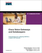
Step 1. Define the gatekeeper to CallManager.
The only information that you need for this step is the IP address of the gatekeeper interface. Be sure that the Enable Device checkbox is also selected. An example is shown in Figure 17-3.
Figure 17-3. ,i>Defining a Gatekeeper to CallManager
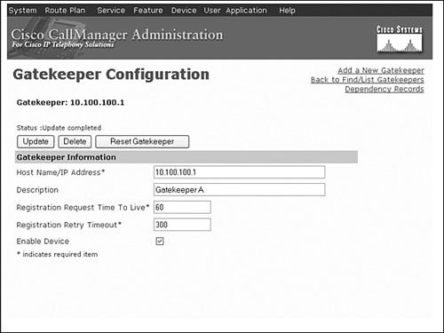
Step 2. Set up the actual trunk to the gatekeeper.
If your CallManager is running software version 3.2 or higher, Cisco recommends using H.225 gatekeeper-controlled trunks.
When you are configuring the trunk, you need to give it a unique name to be used to point traffic to the trunk in the next step. You also need to select the gatekeeper that you defined previously from a drop-down box. Add an appropriate technology prefix. You might want a different technology prefix for CallManager, because CallManager 4.0 and higher systems can handle both voice and video traffic. Always set the Terminal Type field to gateway for normal CAC.
Step 3. Enter the zone name.
It is almost always desirable to have a different zone name for each CallManager cluster that is defined on the gatekeeper. This helps when configuring bandwidth management.
Figure 17-4 shows an example of setting up a gatekeeper trunk. Some of the items on the configuration screen are not related to the gatekeeper and are not shown in this example.
Figure 17-4. Defining a Gatekeeper Trunk on CallManager
At this point, the trunk should be registered to the gatekeeper and ready for use. You can verify this by using the show gatekeeper endpoints command on the gatekeeper, as shown in Example 17-13.
Example 17-13. Verifying CallManager Trunk Registration
GK_A#show gatekeeper endpoints
GATEKEEPER ENDPOINT REGISTRATION
================================
CallSignalAddr Port RASSignalAddr Port Zone Name Type Flags
-------------- ----- ------------- ---- ---- ---- ---- -----
10.1.5.2 56105 10.1.5.2 60570 ny VOIP-GW
H323-ID: GK_Trunk_1
Voice Capacity Max.= Avail.= Current.= 0
10.12.1.2 1720 10.12.1.2 56783 miami VOIP-GW
H323-ID: [email protected]
Voice Capacity Max.= Avail.= Current.= 0
10.1.5.200 1720 10.1.5.200 50240 boise VOIP-GW
E164-ID: 0100
E164-ID: 0101
H323-ID: [email protected]
Voice Capacity Max.= Avail.= Current.= 0
Total number of active registrations = 3
You can provide redundancy on the trunk by assigning up to three subscriber servers to the CallManager redundancy group that is associated with the device pool assigned to the trunk. This configuration causes all servers in the redundancy group to register with the gatekeeper. However, the H.323 trunk name that is used for the h323_id has a suffix of _n, where n is the node number of the CallManager server in the cluster. This ID is assigned automatically and cannot be changed.
This feature provides redundancy without adding administrative complexity. You configure a single trunk, but the gatekeeper registers multiple trunks, one from each subscriber in the CallManager redundancy group.
Step 4. After you have created the trunk, set up CallManager to use the gatekeeper trunk for specific dialed numbers.
You can include the trunk in CallManager route groups, route lists, and route patterns. Figure 17-5 shows a typical CallManager route pattern configuration using the gatekeeper trunk GK_Trunk. Dialed numbers that match this pattern cause CallManager to issue an ARQ to the gatekeeper to resolve the destination gateway IP address for this call.
Figure 17-5. Associating a Route Pattern to the Gatekeeper Trunk
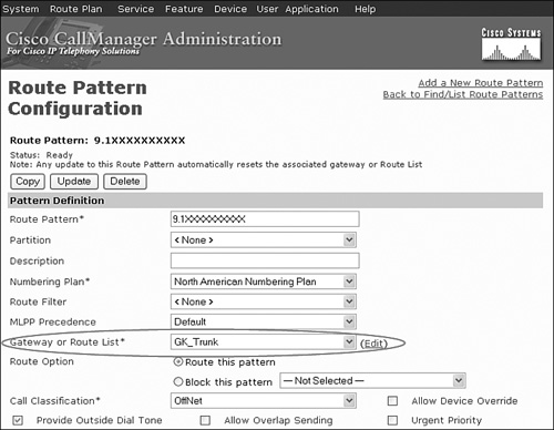
Cisco also recommends that you use the arq reject-unknown-prefix gatekeeper configuration command to prevent potential call routing loops that might occur across redundant CallManager trunks. If a called address does not match any of the known zone prefixes, the gatekeeper attempts to hairpin the call back through the originating gateway without arq reject-unknown-prefix configured. This action might cause loops in a CallManager environment with multiple trunks active to the gatekeeper.
CallManager does not support dynamic zone prefix registration. You must manually code zone prefixes on the gatekeeper for CallManager destinations.
You can verify proper operation and troubleshoot call routing problems in the same manner as with any registered H.323 gateway. CallManager uses the same RAS messaging format for call admission. For more information, see the “Troubleshooting Gatekeepers” section earlier in this chapter.
Gatekeeper Redundancy
A gatekeeper is a critical network component. It is responsible for most or all of the call routing, bandwidth management, and CAC. Because the gatekeeper centrally controls the dial plan, a failure can cause disruptions across the entire voice network under its control. Because of this criticality, it is advisable to implement gatekeeper redundancy to reduce the possibility of service interruptions.
Hot Standby Routing Protocol
One method of gatekeeper redundancy is the use of the Hot Standby Routing Protocol (HSRP). Following are the guidelines and caveats for implementing HSRP on a Cisco IOS gatekeeper:
• Only one gatekeeper is active at any given time.
—The standby gatekeeper does not process calls unless the primary gatekeeper fails.
—No load balancing is supported.
• All gatekeepers must reside on the same subnet.
• No state information is maintained between the gatekeepers, and current state information (calls in progress, bandwidth in use) is lost in the event of a failover. Oversubscription of bandwidth and call degradation is possible immediately after failover.
• Outage duration during a failover might be substantial because the endpoints have to reregister with the standby gatekeeper before calls can be placed. Active calls are not affected.
• Gatekeeper configurations must match exactly between the primary and standby gatekeepers. You must manually replicate any changes or updates to the standby. This adds administrative overhead and increases the chance of errors being introduced into the configuration.
Configuration of HSRP on a gatekeeper is straightforward. HSRP is not supported on a loopback interface, so it is necessary to use a physical interface as the gatekeeper interface. It is preferable to use a LAN interface for this, because LAN interfaces are more reliable than WAN interfaces.
Step 1. Configure IP addresses belonging to the same subnet on the LAN interfaces of both routers.
For example, you could configure FastEthernet0/0 on gatekeeper GK_A as 10.100.100.2, and you could configure FastEthernet0/1 on gatekeeper GK_B as 10.100.100.3.
Step 2. Add a standby address to both interfaces using the standby ip ip-address command.
This address is active on only one of the two gateways at a time. This is the address you should use as the gatekeeper address. Endpoints use this address to register to the gatekeeper. The example uses 10.100.100.1 as the standby IP address.
Step 3. Copy the gatekeeper configuration from the primary to the standby gatekeeper.
After you set up HSRP redundancy, it is imperative that you keep the gatekeeper configuration on both gatekeepers the same. If you make a change on the active router, you should also make it on the standby. Put procedures in place to ensure that the configurations remain synchronized.
If the primary gatekeeper fails or becomes unreachable, the standby gatekeeper assumes the gatekeeper address, and the endpoints reregister to it. This can take up to a couple of minutes. You cannot place calls until the endpoints have reregistered.
HSRP provides an option to force a switch back to the primary after it returns to service. This option is typically not used for gatekeepers, because a switch back causes an unnecessary service interruption.
You can verify the status of each of the gatekeepers using the show standby and show gatekeeper status commands. Example 17-14 shows a dual gatekeeper HSRP redundancy configuration.
Example 17-14. Gatekeeper Redundancy Using HSRP
GATEKEEPER A
GK_A#show running-config
Building configuration...
!
! Unnecessary output deleted
!
interface FastEthernet0/0
ip address 10.100.100.2 255.255.255.240
standby ip 10.100.100.1
!
gatekeeper
zone local ny cisco.com 10.100.100.1
zone local boise cisco.com
zone local miami cisco.com
zone prefix ny 2...
gw-type-prefix 1#* default-technology
rrq dynamic-prefixes-accept
arq reject-unknown-prefix
bandwidth interzone zone boise 16
no shutdown
!
end
GK_A#show gatekeeper status
Gatekeeper State: UP
Load Balancing: DISABLED
Flow Control: DISABLED
Zone Name: ny
Zone Name: boise
Zone Name: miami
Accounting: DISABLED
Endpoint Throttling: DISABLED
Security: DISABLED
Maximum Remote Bandwidth: unlimited
Current Remote Bandwidth: 0 kbps
Current Remote Bandwidth (w/ Alt GKs): 0 kbps
GK_A#show standby
FastEthernet0/0 - Group 0
State is Active
5 state changes, last state change 00:03:08
Virtual IP address is 10.100.100.1
Active virtual MAC address is 0000.0c07.ac00
Local virtual MAC address is 0000.0c07.ac00 (v1 default)
Hello time 3 sec, hold time 10 sec
Next hello sent in 0.816 secs
Preemption disabled
Active router is local
Standby router is 10.100.100.3, priority 100 (expires in 8.924 sec)
Priority 100 (Default 100)
IP redundancy name is "hsrp-Fa0/0-0" (default)
GATEKEEPER B
GK_B#show running-config
Building configuration...
!
! Unnecessary output deleted
!
interface FastEthernet0/0
ip address 10.100.100.3 255.255.255.240
standby ip 10.100.100.1
!
gatekeeper
zone local ny cisco.com 10.100.100.1
zone local boise cisco.com
zone local miami cisco.com
zone prefix ny 2...
gw-type-prefix 1#* default-technology
rrq dynamic-prefixes-accept
arq reject-unknown-prefix
bandwidth interzone zone boise 16
no shutdown
!
end
GK_B#show gatekeeper status
Gatekeeper State: HSRP STANDBY
Load Balancing: DISABLED
Flow Control: DISABLED
Zone Name: ny
Zone Name: boise
Zone Name: miami
Accounting: DISABLED
Endpoint Throttling: DISABLED
Security: DISABLED
Maximum Remote Bandwidth: unlimited
Current Remote Bandwidth: 0 kbps
Current Remote Bandwidth (w/ Alt GKs): 0 kbps
GK_B#show standby
FastEthernet0/0 - Group 0
State is Standby
4 state changes, last state change 00:06:04
Virtual IP address is 10.100.100.1
Active virtual MAC address is 0000.0c07.ac00
Local virtual MAC address is 0000.0c07.ac00 (v1 default)
Hello time 3 sec, hold time 10 sec
Next hello sent in 1.880 secs
Preemption disabled
Active router is 10.100.100.2, priority 110 (expires in 8.020 sec)
Standby router is local
Priority 100 (default 100)
IP redundancy name is "hsrp-Fa0/0-0" (default)
Gatekeeper Clustering
The gatekeeper cluster feature allows multiple gatekeepers to control one zone. When an endpoint, such as a voice gateway, registers with a gatekeeper, it is provided with a list of alternate gatekeepers for the zone in which it registers. These alternates were specified in the gatekeeper configuration. If the gatekeeper fails, the endpoint can use the alternate gatekeepers to continue operation.
Note
Use of the alternate gatekeeper features requires Cisco IOS Software Release 12.2(1)T or later. CallManager Version 3.3 or later is required for redundancy on gatekeeper-controlled trunks.
Configuring gatekeeper clusters can be confusing. Each local zone is represented by a different name on each cluster member. It can help clarify if you think of a zone as having a “base name” and then an alias on the other cluster members. The gateways use the “base name” when they register to the gatekeeper zone.
For example, if a local zone base name is boise, and it is in a cluster with two alternate gatekeepers, you could use the names boise_gka and boise_gkb for the alternates. This could represent gatekeeper alternative A (gka) and gatekeeper alternative B (gkb) for the zone. In reality, the actual names used on the alternates can be anything as long as they are unique. Developing a naming scheme that has some meaning can help you to keep everything straight as you build the configuration.
Zone configuration is done in gatekeeper configuration mode. When you are configuring the gatekeeper, every local zone is listed with a zone local command and a zone cluster command. The zone local command defines the zone as it is known to the local gatekeeper. The zone cluster command identifies aliases for the zone and the IP addresses of the alternate gatekeepers that can process requests for that zone. The command format is zone cluster local cluster-name zone-name. The zone-name must match what is defined in the zone local statement. Aliases for the zones (names of the zones as they are known on alternate gatekeepers) are defined using the element zone-alias ip-address command. The IP address is that of the gatekeeper interface on the alternate gatekeeper where that zone alias is defined.
You might also find occasions where you want one gatekeeper to be primary for some zones and other gatekeepers as primary for other zones. This might be because of network topology, proximity, or other factors.
The following shows how a simple cluster can be built, based on the sample network. The sample network contains three local zones: ny, boise, and miami. GK_A is the primary gatekeeper for zone miami, and it is the alternate for ny and boise. GK_B is the primary for zones ny and boise, and it is the alternate for zone miami. Table 17-1 lists the names and aliases that are used to build the cluster.
Table 17-1. Example Gatekeeper Cluster Zone Names
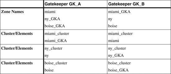
After you have determined all the names, you can begin to configure the gatekeepers in the cluster. The configuration that you can apply for Gatekeeper GK_A and GK_B is shown in Example 17-15.
Example 17-15. Simple Gatekeeper Cluster Configuration
GATEKEEPER A
GK_A#show running-config
Building configuration...
!
! Unnecessary output deleted
!
interface Loopback0
description Gatekeeper A
ip address 10.100.100.1 255.255.255.255
!
gatekeeper
zone local miami cisco.com 10.100.100.1
zone local boise_GKA cisco.com
zone local ny_GKA cisco.com
zone cluster local miami_cluster miami
element miami_GKA 10.100.101.1 1719
!
zone cluster local boise_cluster boise_GKA
element boise 10.100.101.1 1719
!
zone cluster local ny_cluster ny_GKA
element ny 10.100.101.1 1719
!
zone prefix ny_GKA 2...
gw-type-prefix 1#* default-technology
rrq dynamic-prefixes-accept
arq reject-unknown-prefix
bandwidth interzone zone boise_GKA 16
no shutdown
!
end
GATEKEEPER B
GK_B#show running-config
Building configuration...
!
! Unnecessary output deleted
!
interface Loopback0
description Gatekeeper B
ip address 10.100.101.1 255.255.255.255
!
gatekeeper
zone local ny cisco.com 10.100.101.1
zone local boise cisco.com
zone local miami_GKA cisco.com
zone cluster local ny_cluster ny
element ny_GKA 10.100.100.1 1719
!
zone cluster local boise_cluster boise
element boise_GKA 10.100.100.1 1719
!
zone cluster local miami_cluster miami_GKA
element miami 10.100.100.1 1719
!
zone prefix ny 2...
gw-type-prefix 1#* default-technology
rrq dynamic-prefixes-accept
arq reject-unknown-prefix
bandwidth interzone zone boise 16
no shutdown
!
end
Several tools are available to verify the setup and status of the cluster. These tools include the show gatekeeper endpoint, show gatekeeper status cluster, show gatekeeper cluster, and show gatekeeper zone cluster commands.
Example 17-16 demonstrates output from each of these commands.
Example 17-16. Gatekeeper Cluster show Commands
DEFINED CLUSTERS AND THEIR ELEMENTS
GK_B#show gatekeeper clusters
CONFIGURED CLUSTERS
===================
Cluster Name Type Local Zone Elements IP
------------ ---- ---------- -------- --
ny_cluster Local ny ny_GKA 10.100.100.1 1719
boise_cluster Local boise boise_GKA 10.100.100.1 1719
miami_cluster Local miami_GKA miami 10.100.100.1 1719
CURRENT STATUS OF THE CLUSTER
GK_B#show gatekeeper status cluster
CLUSTER INFORMATION
===================
Active Endpoint Last
Hostname %Mem %CPU Calls Count Announce
-------- ----- ---- ----- ----- --------
GK_B 71 1 0 2 Local Host
GK_A 19 0 0 1 5s
CLUSTER INFORMATION BY ZONE
GK_B#show gatekeeper zone cluster
LOCAL CLUSTER INFORMATION
=========================
TOT BW INT BW REM BW LAST ALT GK
LOCAL GK NAME ALT GK NAME PRI (kbps) (kbps) (kbps) ANNOUNCE STATUS
------------- ----------- --- ------ ------ ------ --------- ------
ny ny_GKA 7 0 0 0 20s CONNECTED
boise boise_GKA 7 0 0 0 20s CONNECTED
miami_GKA miami 7 0 0 0 20s CONNECTED
REGISTERED ENDPOINTS
GK_B#show gatekeeper endpoint
GATEKEEPER ENDPOINT REGISTRATION
================================
CallSignalAddr Port RASSignalAddr Port Zone Name Type Flags
-------------- ----- -------------- ----- --------- ---- -----
10.1.5.2 61817 10.1.5.2 61819 ny VOIP-GW
H323-ID: GK_Trunk_1
Voice Capacity Max.= Avail.= Current.= 0
10.12.1.2 1720 10.12.1.2 52237 miami_GKA VOIP-GW A
H323-ID: [email protected]
10.1.5.200 1720 10.1.5.200 50240 boise VOIP-GW
E164-ID: 0100
E164-ID: 0101
H323-ID: [email protected]
Voice Capacity Max.= Avail.= Current.= 0
Total number of active registrations = 3
In the show gatekeeper endpoint output, the A flag listed after the miami_GKA zone indicates that this gatekeeper is currently alternate for that zone. Absence of the A flag means that this is the active gatekeeper for the zone.
Load Balancing
Load balancing allows the gatekeeper to move registered endpoints to an alternate gatekeeper or to reject new calls and registrations after a threshold is met. Load balancing requires that alternate gatekeepers be configured.
The syntax for the command to set up load balancing is load-balance [endpoints max-endpoints] [calls max-calls] [cpu max-cpu] [memory max-memory-used]. You apply this in gatekeeper configuration mode on each gatekeeper in the cluster where you want to load-balance. You can concatenate the parameters together to allow monitoring of multiple thresholds.
To verify that load balancing is enabled, use the show gatekeeper status command, as demonstrated in Example 17-17. The last four lines are displayed only when load balancing is enabled.
Example 17-17. Gatekeeper Load Balancing
GK_A#show gatekeeper status
Gatekeeper State: UP
Load Balancing: ENABLED
Flow Control: DISABLED
Zone Name: miami
Zone Name: boise_GKA
Zone Name: ny_GKA
Accounting: DISABLED
Endpoint Throttling: DISABLED
Security: DISABLED
Maximum Remote Bandwidth: unlimited
Current Remote Bandwidth: 0 kbps
Current Remote Bandwidth (w/ Alt GKs): 0 kbps
Call Capacity: 0 / 100
Endpoint Capacity: 1 / 100
Memory Utilization: 19% / 70%
CPU Utilization: 0% / 80%
Troubleshooting Gatekeeper Clustering
Gatekeepers that are members of a cluster communicate with each other to update their status by using GUP. GUP messages are sent between cluster members periodically or when the status has changed. Each member gatekeeper in the cluster maintains the state information about activity on all the other gatekeepers. With that state information, failover to an alternate gatekeeper can be seamlessly completed. For more information on the GUP protocol, see the “Gatekeeper Update Protocol” section in Chapter 16.
You can use the debug gatekeeper gup asn1 command to determine if the proper information is being passed in the GUP messages. The output of this trace allows you to easily determine if the updates are occurring and if they contain valid information. The number of calls by zone, the bandwidth used, and the load balancing information are included in the GUP announcement messages. You can use this information in addition to the troubleshooting tools previously discussed to help isolate problems with the gatekeepers.
Example 17-18 shows GUP messages that are sent to alternate gatekeepers within the cluster when a call is placed from Boise to Miami.
Example 17-18. debug gatekeeper gup asn1 Trace Output
GK_A#debug gatekeeper gup asn1
*Aug 6 08:31:40.103: GUP INCOMING PDU ::=
value GUP_Information ::=
{
protocolIdentifier { 1 2 840 113548 10 0 0 4 }
message announcementIndication :
{
announcementInterval 30
endpointCapacity 24658
callCapacity 24284
hostName '474B5F42'H
percentMemory 71
percentCPU 1
currentCalls 1 ## 1 call in progress
currentEndpoints 1
zoneInformation
{
{
gatekeeperIdentifier {"ny"}
altGKIdentifier {"ny_GKA"}
totalBandwidth 0
un interzoneBandwidth 0
remoteBandwidth 0
},
{
gatekeeperIdentifier {"boise"}
altGKIdentifier {"boise_GKA"}
totalBandwidth 160
interzoneBandwidth 160 ## 16Kb Bandwidth Currently in Use
remoteBandwidth 0
},
{
gatekeeperIdentifier {"miami_GKA"}
altGKIdentifier {"miami"}
totalBandwidth 0
interzoneBandwidth 0
remoteBandwidth 0
}
}
}
}
*Aug 6 08:31:40.123: Received GUP ANNOUNCEMENT INDICATION from 10.100.101.1
Configuring Resource Availability Indicator
The Resource Availability Indication (RAI) is a mechanism by which gateways can report the status of resources to the gatekeeper. If RAI is enabled, the gateway tracks the status of DS0 channels and DSP resources. This feature only tracks DS0s and DSP resources; analog trunk ports are not included.
RAI is useful in locations where more than one gateway is servicing a destination. An example of this might be a large location with multiple PSTN connections. You can have multiple trunks dispersed across several gateways for increased capacity and redundancy.
When RAI is enabled, resources are tracked against a defined threshold. When the high resource threshold is exceeded, an RAI message is sent to the gatekeeper indicating that the gateway is almost out of resources. When the resources have become available again and the low threshold is met, another RAI message is sent to the gatekeeper indicating that the gateway is no longer resource constrained.
The gatekeeper assigns a priority to gateways. If multiple gateways service the same destination, the gatekeeper routes the calls based on the gateway priority. If all the gateways have the same priority, the gatekeeper load-balances across them. The default gateway priority is 5. You can change the priority of a specific gateway using the zone prefix gatekeeper-name e164-prefix [gw-priority priority gw-alias [gw-alias,...]] command. You can set the priority in a range from 0 to 10. The gw-alias is the H323-ID of the gateway that you want to change.
When the gatekeeper receives an RAI from a gateway indicating that it is almost out of resources, it lowers the priority of that gateway to 1. When that occurs, the gatekeeper sends calls to the other gateways that are servicing the destination with higher priorities. If no other gateway has a higher priority or if all gateways in that zone have priority 1, the gatekeeper still sends calls to the gateway that sent the RAI message.
When the low threshold is met and the gatekeeper receives the RAI message indicating that resources are again available, it restores the priority of the gateway to the original value.
No configuration is necessary on the gatekeeper to enable RAI.
RAI is enabled on the gateway using the resource threshold [high percentage-value] [low percentage-value] [report-policy {idle-only | addressable}] command in gateway configuration mode. The optional report-policy parameter determines how to calculate resource utilization:
• idle-only—Utilization = (in-use)/(in-use plus free)
• addressable—Utilization = (in-use plus disabled)/addressable
The addressable channel calculation includes disabled channels; therefore, it provides a more accurate percentage of available channels.
You can also optionally code the lrq reject-resource-low command on the gatekeeper. Normally, all requests are processed even if the destination gateways are reporting that they are almost out of resources. If the lrq reject-resource-low command is included, the gatekeeper can reject (issue a Location Reject, or LRJ) requests from remote zones to a destination that is resource constrained.
Example 17-19 shows the configuration that is necessary to enable RAI on a gateway.
Leeds#show running-config
Building configuration...
!
! Unnecessary output deleted
!
controller E1 1/0
ds0-group 1 timeslots 1-4 type r2-digital r2-compelled ani
!
!
interface Serial0/0.102 point-to-point
ip address 10.13.1.2 255.255.255.0
frame-relay interface-dlci 102
h323-gateway voip interface
h323-gateway voip id leeds multicast
h323-gateway voip h323-id [email protected]
h323-gateway voip tech-prefix 1#
h323-gateway voip bind srcaddr 10.13.1.2
!
!
voice-port 1/0:1
!
voice-port 2/0/0
!
voice-port 2/0/1
!
voice-port 2/0/2
!
voice-port 2/0/3
!
dial-peer voice 99 voip
destination-pattern .T
session target ras
codec g711ulaw
!
dial-peer voice 1 pots
destination-pattern 0113496....
no digit-strip
port 1/0:1
!
!
gateway
resource threshold high 75 low 50
!
end
In the example, only four timeslots are enabled on the E1 trunk. The high threshold is 75 percent, and the low threshold is 50 percent. Voice port 1/0:1 is referenced in a dial peer, making the channels addressable. This is important—only DS0s that are associated with a POTS dial peer are monitored. Usage of available DSP resources is also monitored and compared to the thresholds for RAI reporting.
Even though the gateway has analog voice ports, only the DS0 ports are included in calculating resource usage.
You can see which resources are being monitored and which thresholds are in use by using the show gateway command, as demonstrated in Example 17-20.
Example 17-20. Displaying Resource Thresholds
Leeds#show gateway
H.323 ITU-T Version: 4.0 H323 Stack Version: 0.1
H.323 service is up
Gateway [email protected] is registered to Gatekeeper leeds
Alias list (CLI configured)
H323-ID [email protected]
Alias list (last RCF)
H323-ID [email protected]
H323 resource thresholding is Enabled and Active
H323 resource threshold values:
DSP: Low threshold 50, High threshold 75
DS0: Low threshold 50, High threshold 75
To see the status of monitored DS0 and DSP resources, use the show call resource voice stats command. To see whether any of the configured thresholds have been exceeded, use the show voice resource call threshold command. Example 17-21 shows the results of both of these commands, in addition to the show gatekeeper endpoint command.
Example 17-21. Displaying Resource Status
CURRENT STATUS OF MONITORED RESOURCES
Leeds#show call resource voice stats
Resource Monitor - Dial-up Resource Statistics Information:
DSP Statistics:
Utilization: 0.00 percent
Total channels: 76
Inuse channels: 0
Disabled channels: 0
Pending channels: 0
Free channels: 76
DS0 Statistics:
Utilization: 0.00 percent
Total channels: 31
Addressable channels: 4
Inuse channels: 0
Disabled channels: 4
Free channels: 0
THRESHOLD STATE INFORMATION
Leeds#show call resource voice threshold
Resource Monitor - Dial-up Resource Threshold Information:
DS0 Threshold:
Client Type: h323
High Water Mark: 75
Low Water Mark: 50
Threshold State: high_threshold_hit
DSP Threshold:
Client Type: h323
High Water Mark: 75
Low Water Mark: 50
Threshold State: low_threshold_hit
GATEWAY STATUS REPORTED BY GATEKEEPER
HQ#sho gatekeeper endpoints
GATEKEEPER ENDPOINT REGISTRATION
================================
CallSignalAddr Port RASSignalAddr Port Zone Name Type Flags
-------------- ----- -------------- ----- ---------- ----- ------
10.12.1.2 1720 10.12.1.2 50196 miami VOIP-GW
H323-ID: [email protected]
Voice Capacity Max.= Avail.= Current.= 0
10.13.1.2 1720 10.13.1.2 51289 leeds VOIP-GW O
H323-ID: [email protected]
Voice Capacity Max.= Avail.= Current.= 0
10.1.5.200 1720 10.1.5.200 51942 boise H323-GW
H323-ID: [email protected]
Voice Capacity Max.= Avail.= Current.= 0
Total number of active registrations = 3
In the example, you can see that 76 DSP resources exist, and all are free. Four DS0 resources are available, and all four are disabled, leaving zero free. This means that the gateway should be telling the gatekeeper that it is resource constrained via an RAI message. The show gatekeeper endpoints command in the example lists the leeds gateway with an O flag. This confirms that the gatekeeper has received the RAI message, and the gateway is flagged as out of resources.
You can also see the actual RAI message sent by the gateway and the gatekeeper response using the debug h225 asn1 trace command. Example 17-22 shows the RAI that is sent to the gatekeeper.
Example 17-22. RAI Message Captured with debug h225 asn1 Trace
Leeds#debug h225 asn1
*Jun 25 19:41:27.537: RAS OUTGOING PDU ::=
value RasMessage ::= resourcesAvailableIndicate :
{
requestSeqNum 1746
protocolIdentifier { 0 0 8 2250 0 4 }
endpointIdentifier {"8413BC2400000003"}
protocols
{
voice :
{
supportedPrefixes
{
{
prefix dialedDigits : "1#"
}
}
}, h323 :
{
supportedPrefixes
{
}
}
}
almostOutOfResources TRUE
}
*Jun 25 19:41:27.537: RAS OUTGOING ENCODE BUFFER::= 81380006D1060008914A00041E00
38003400310033004200430032003400300030003000300030003000300033023C0504010020402C
05010080
*Jun 25 19:41:27.537:
*Jun 25 19:41:27.577: RAS INCOMING ENCODE BUFFER::= 820A0006D1060008914A0004
*Jun 25 19:41:27.577:
*Jun 25 19:41:27.577: RAS INCOMING PDU ::=
value RasMessage ::= resourcesAvailableConfirm :
{
requestSeqNum 1746
protocolIdentifier { 0 0 8 2250 0 4 }
}
In the trace, the almostOutOfResources flag is set to TRUE, informing the gatekeeper of a resource constraint. The gatekeeper acknowledges with a resourcesAvailableConfirm message, changes the priority of the gateway to 1, and sets the O status flag.
Configuring Gatekeeper Security
The options that are available for securing the gatekeeper-controlled H.323 network were discussed in Chapter 16. Proper planning and design up front of the desired security function simplifies the configuration.
To configure the gatekeeper to authenticate requests, it is first necessary to set up the authentication, authorization, and accounting feature (AAA) within Cisco IOS. AAA can use credentials that are configured in either a local database on the gatekeeper or an external RADIUS security server such as the Cisco Secure Access Control Server (ACS). AAA can also send accounting records to the RADIUS server to track events such as call duration, invalid login attempts, and so on.
The exact AAA configuration depends on several factors that are beyond the scope of this book. For guidance configuring AAA, please refer to Cisco.com.
When you are using authentication, it is important that you synchronize the time between the gatekeeper and all the gateways on the network. The Network Time Protocol (NTP) is the best way to accomplish this. To enable NTP, use the ntp server <server addr> command in global configuration mode. The <server addr> should be that of a known good NTP time source that is reachable on the network. More information on configuring NTP is available on Cisco.com.
The security token required-for all | registration command is used on the gatekeeper to authenticate gateways during registration or to do per-call authentication. If the registration option is selected, the gateway credentials are validated before the gateway can successfully register. If the all option is used, credentials are checked during registration and for each call that is presented to the gatekeeper.
On the gateway, the security password wordall | endpoint | per-call command is used in gateway configuration mode. If the endpoint option is selected, authentication occurs only during registration. The per-call option causes credentials to be sent on every call request. The all option enables both registration and per-call authentication. The word parameter sets the password to be used for the gateway.
You can use the tokenless call authentication feature for endpoints that do not support tokens, such as CallManager. To configure tokenless call authentication, you must create an access control list (ACL) on the gatekeeper. The ACL must include permit statements for the IP address of every device that is authorized to place call routing requests to the gatekeeper.
After you create the ACL, you enter the command security acl answerarq <1-99> in gatekeeper configuration mode. The <1-99> parameter refers to the ACL you just created. When this is complete, all ARQs that are received from gateways that have IP addresses permitted by the ACL are answered, whether or not they contain a security token.
It is important to note that tokenless call authentication applies to ARQs only and has no effect on gateway registration with the gatekeeper. Also, you can use token-based and tokenless call authentication at the same time. They are not mutually exclusive.
Example 17-23 shows the configuration that is necessary to enable gateway registration authentication. In this example, per-call authentication is not being done. The AAA feature is using locally configured user IDs and passwords rather than a RADIUS server.
Example 17-23. Enabling Gateway Registration Security
BOISE GATEWAY
boise#show running-config
Building configuration...
!
! Unnecessary output deleted
!
interface FastEthernet0/0
ip address 10.1.5.200 255.255.255.0
h323-gateway voip interface
h323-gateway voip id boise multicast
h323-gateway voip h323-id [email protected]
h323-gateway voip tech-prefix 1#
h323-gateway voip bind srcaddr 10.1.5.200
!
gateway
security password goodguy level endpoint
!
end
GATEKEEPER A
GKA#show running-config
Building configuration...
!
! Unnecessary output deleted
!
username [email protected] password 0 goodguy
username [email protected] password 0 goodguy
username [email protected] password 0 goodguy
!
aaa new-model
!
!
aaa authentication login default local
aaa authentication login h323 local
aaa authorization exec default local
aaa authorization exec h323 local
!
gatekeeper
zone local boise cisco.com 10.1.5.1
zone local miami cisco.com
zone local leeds cisco.com
zone prefix miami 21........
security token required-for registration
gw-type-prefix 1#* default-technology
rrq dynamic-prefixes-accept
arq reject-unknown-prefix
bandwidth interzone default 64
no shutdown
!
!
ntp server 10.1.5.200
!
end
If a RADIUS server such as Cisco Secure ACS had been used, the credentials would not have appeared in the Cisco IOS configuration. Also note that NTP has been configured and is being used to synchronize the gatekeeper clock.
CallManager does not support tokens for either registration or per-call security. If CallManager trunks are in use, you cannot enable registration security; otherwise, the CallManager trunk is unable to register. You can use per-call security with CallManager by using the tokenless call authentication feature.
Troubleshooting Gatekeeper Security
If registration or call routing problems occur due to security, you can use one of several tools to determine the problem. Some common causes of security issues include the following:
• Clocks not synchronized—If is the difference is too great between the time stamps on the request and the time in the gatekeeper, the request is rejected. Be sure that NTP is set up and working properly. You can use the show ntp status command to quickly verify NTP operation.
• User ID mismatch—The user ID that is used is the full H.323-ID. The user ID credentials must match.
• No token being presented—Some devices cannot use token authentication, as discussed previously.
Some of the tools that can assist in finding the cause of a problem include the debug h225 asn1, debug gatekeeper main 5, debug aaa authentication, and debug aaa attr trace commands. Example 17-24 shows how the debug h225 asn1 trace can assist with a gateway registration problem.
Example 17-24. Failed Gateway Registration debug h225 asn1 Trace
May 17 14:23:23.717: RAS OUTGOING PDU ::=
value RasMessage ::= registrationRequest :
{
requestSeqNum 1150
protocolIdentifier { 0 0 8 2250 0 4 }
discoveryComplete TRUE
callSignalAddress
{
ipAddress :
{
ip '0A0105C8'H
port 1720
}
}
rasAddress
{
ipAddress :
{
ip '0A0105C8'H
port 56775
}
}
terminalType
{
vendor
{
vendor
{
t35CountryCode 181
t35Extension 0
manufacturerCode 18
}
productId '436973636F47617465776179'H
versionId '32'H
}
gateway
{
protocol
{
voice :
{
supportedPrefixes
{
{
prefix dialedDigits : "1#"
}
}
}, h323 :
{
supportedPrefixes
{
}
}
}
}
mc FALSE
undefinedNode FALSE
}
terminalAlias
{
h323-ID : {"[email protected]"}
}
gatekeeperIdentifier {"boise"}
endpointVendor
{
vendor
{
t35CountryCode 181
t35Extension 0
manufacturerCode 18
}
productId '436973636F47617465776179'H
versionId '32'H
}
timeToLive 60
keepAlive FALSE
willSupplyUUIEs FALSE
maintainConnection TRUE
usageReportingCapability
{
nonStandardUsageTypes
{
{
nonStandardIdentifier h221NonStandard :
{
t35CountryCode 181
t35Extension 0
manufacturerCode 18
}
data '40'H
}
}
startTime NULL
endTime NULL
terminationCause NULL
}
}
May 17 14:23:23.865:
May 17 14:23:23.865: RAS INCOMING PDU ::=
value RasMessage ::= registrationReject :
{
requestSeqNum 1150
protocolIdentifier { 0 0 8 2250 0 4 }
rejectReason securityDenial : NULL
gatekeeperIdentifier {"boise"}
}
You can see that the registration request from the Boise gateway was rejected because of securityDenial. In this case, no security information was included in the RRQ. This most likely indicates a configuration error in the gateway. Example 17-25 shows the successful registration process after the configuration was corrected.
Example 17-25. Successful Gateway Registration debug h225 asn1 Trace
value RasMessage ::= registrationRequest :
{
requestSeqNum 1170
protocolIdentifier { 0 0 8 2250 0 4 }
discoveryComplete TRUE
callSignalAddress
{
ipAddress :
{
ip '0A0105C8'H
port 1720
}
}
rasAddress
{
ipAddress :
{
ip '0A0105C8'H
port 52091
}
}
terminalType
{
vendor
{
vendor
{
t35CountryCode 181
t35Extension 0
manufacturerCode 18
}
productId '436973636F47617465776179'H
versionId '32'H
}
gateway
{
protocol
{
voice :
{
supportedPrefixes
{
{
prefix dialedDigits : "1#"
}
}
}, h323 :
{
supportedPrefixes
{
}
}
}
}
mc FALSE
undefinedNode FALSE
}
terminalAlias
{
h323-ID : {"[email protected]"}
}
gatekeeperIdentifier {"boise"}
endpointVendor
{
vendor
{
t35CountryCode 181
t35Extension 0
manufacturerCode 18
}
productId '436973636F47617465776179'H
versionId '32'H
}
timeToLive 60
tokens
{
{
tokenOID { 1 2 840 113548 10 1 2 1 }
timeStamp 1147876446
challenge 'F64FAD4A17AFE3C1D0D51ADF38071BA8'H
random 164
generalID {"[email protected]"}
}
}
cryptoTokens
{
cryptoEPPwdHash :
{
alias h323-ID : {"[email protected]"}
timeStamp 1147876446
token
{
algorithmOID { 1 2 840 113549 2 5 }
paramS
{
}
hash "6D01394D6E13493CB7338E16EADDB9F"
}
}
}
keepAlive FALSE
willSupplyUUIEs FALSE
maintainConnection TRUE
usageReportingCapability
{
nonStandardUsageTypes
{
{
nonStandardIdentifier h221NonStandard :
{
t35CountryCode 181
t35Extension 0
manufacturerCode 18
}
data '40'H
}
}
startTime NULL
endTime NULL
terminationCause NULL
}
}
May 17 14:34:07.073: RAS INCOMING PDU ::=
value RasMessage ::= registrationConfirm :
{
requestSeqNum 1170
protocolIdentifier { 0 0 8 2250 0 4 }
callSignalAddress
{
}
terminalAlias
{
h323-ID : {"[email protected]"}
}
gatekeeperIdentifier {"boise"}
endpointIdentifier {"840F50B400000003"}
alternateGatekeeper
{
}
timeToLive 60
willRespondToIRR FALSE
maintainConnection TRUE
supportsAdditiveRegistration NULL
usageSpec
{
{
when
{
end NULL
inIrr NULL
}
callStartingPoint
{
connect NULL
}
required
{
nonStandardUsageTypes
{
}
startTime NULL
endTime NULL
terminationCause NULL
}
}
}
}
In this example, you can see that both the Cisco Access Token (CAT) and H.235 cryptoToken are included in the RRQ. The Cisco gatekeeper only processes the CAT; it ignores the cryptoToken. The cryptoToken is included for compatibility with third-party gatekeepers. You can also see the H.323 ID and timestamp in the trace output.
Case Study: Deploying Gatekeepers to Assist in Migration to VoIP
Your company migration to an IP Telephony infrastructure is well underway. Three out of six sites are completely converted. The design uses a centralized CallManager deployment at the New York headquarters location. CallManager location-based CAC is being used for CAC to the sites that have been converted. PBXs are still being used at the New York, Boise, and Shanghai locations.
Gatekeepers are being deployed as part of the migration. Two gatekeepers are located at the New York office and configured as a redundant cluster. You need to configure them to provide call routing between the IP Telephony sites and the PBX locations. The gatekeepers should also provide CAC to the locations that have a PBX. Figure 17-6 illustrates details of the network topology.
Figure 17-6. Example Voice Network Topology
Planning the configuration prior to beginning deployment helps eliminate confusion and ensure a smooth rollout. As discussed previously, it is useful to lay out all the naming information in advance to simplify building of the gatekeeper cluster definitions. Zones have to be created for New York, Boise, Shanghai, and CallManager. The zone for CallManager will be used to route calls between sites with a PBX and sites that are CallManager controlled with IP Telephony endpoints.
The physical trunk count provides CAC for the Boise location, so the gatekeeper does not have to control it. Only three E&M trunks exist between the gateway and the PBX, so concurrent calls are limited to three.
The New York headquarters location has high bandwidth links, so you do not need to limit calls to that zone in the gatekeeper.
Shanghai has an E1 and a fairly high data requirement, so you should limit calls to that zone to a concurrent maximum of 20. A G.729 codec is used for all calls across the WAN. Because the gatekeeper uses a value of 16 Kb for each G.729 call, you need to set the limit to the Shanghai zone to 320 Kb (20 calls * 16 Kb).
CallManager is using location-based CAC to limit calls to remote IP Telephony sites, so you do not need to limit the bandwidth in the gatekeeper to that zone.
Zone prefixes are explicitly defined to the gatekeeper. Dynamic prefix registration is not used. This can provide more flexibility by allowing more generic prefixes to be defined to the gatekeeper to get the call to the right gateway. At that point, the dial peers in the gateway can selectively route the call to its destination.
Table 17-2 provides information on the gatekeeper planning for the case study.
Table 17-2. Case Study Gatekeeper Planning

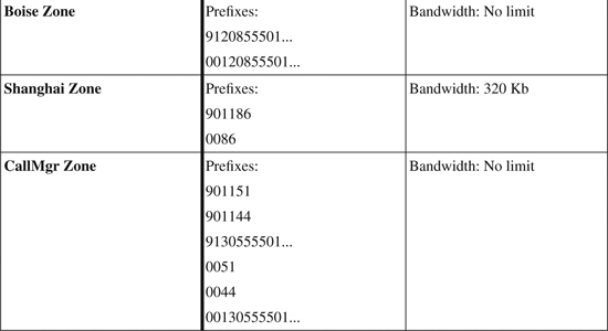
To begin implementation, set up two Cisco IOS routers as gatekeepers. To provide a high level of redundancy, locate these routers on separate power sources and Ethernet switches at the New York location. The gatekeeper interface on gatekeeper GK1 has an IP address of 10.100.100.1. Gatekeeper GK2 has an IP address of 10.200.200.1.
You can do all the gatekeeper configuration in advance. Subsequently, you can configure the gateways individually and verify them as dictated by the migration schedule.
Example 17-26 shows the full configuration of both gatekeepers that are necessary to support the design requirements. Be sure to add the arq reject-unknown-prefix command to prevent loops on the redundant CallManager trunks. The bandwidth interzone zone shanghai 320 command limits the number of calls between any other location and Shanghai to 20 as planned.
Example 17-26. Case Study Gatekeeper Configuration
GATEKEEPER GK1
GK1#show running-config
Building configuration...
!
! Unnecessary output deleted
!
interface Loopback0
description Gatekeeper GK1
ip address 10.100.100.1 255.255.255.255
!
gatekeeper
zone local ny acme.com 10.100.100.1
zone local boise acme.com
zone local shanghai acme.com
zone local callmgr acme.com
zone cluster local ny_cluster ny
element ny_alt 10.200.200.1 1719
!
zone cluster local boise_cluster boise
element boise_alt 10.200.200.1 1719
!
zone cluster local shanghai_cluster shanghai
element shanghai_alt 10.200.200.1 1719
!
zone cluster local callmgr_cluster callmgr
element callmgr_alt 10.200.200.1 1719
!
zone prefix ny 912125552...
zone prefix ny 912125553...
zone prefix ny 0012125552...
zone prefix ny 0012125553...
zone prefix boise 9120855501..
zone prefix boise 00120855501..
zone prefix shanghai 901186*
zone prefix shanghai 0086*
zone prefix callmgr 901151*
zone prefix callmgr 901144*
zone prefix callmgr 9130555501..
zone prefix callmgr 0051*
zone prefix callmgr 0044*
zone prefix callmgr 00130555501..
zone prefix callmgr 9*
zone prefix callmgr 001*
gw-type-prefix 1#* default-technology
arq reject-unknown-prefix
bandwidth interzone zone shanghai 320
no shutdown
!
end
GATEKEEPER GK2
GK2#show running-config
Building configuration...
!
! Unnecessary output deleted
!
interface Loopback0
description Gatekeeper GK2
ip address 10.200.200.1 255.255.255.255
!
gatekeeper
zone local ny_alt acme.com 10.200.200.1
zone local boise_alt acme.com
zone local shanghai_alt acme.com
zone local callmgr_alt acme.com
zone cluster local ny_cluster ny_alt
element ny 10.100.100.1 1719
!
zone cluster local boise_cluster boise_alt
element boise 10.100.100.1 1719
!
zone cluster local shanghai_cluster shanghai_alt
element shanghai 10.100.100.1 1719
!
zone cluster local callmgr_cluster callmgr_alt
element callmgr 10.100.100.1 1719
!
zone prefix ny_alt 912125552...
zone prefix ny_alt 912125553...
zone prefix ny_alt 0012125552...
zone prefix ny_alt 0012125553...
zone prefix boise_alt 9120855501..
zone prefix boise_alt 00120855501..
zone prefix shanghai_alt 901186*
zone prefix shanghai_alt 0086*
zone prefix callmgr_alt 901151*
zone prefix callmgr_alt 901144*
zone prefix callmgr_alt 9130555501..
zone prefix callmgr_alt 0051*
zone prefix callmgr_alt 0044*
zone prefix callmgr_alt 00130555501..
zone prefix callmgr_alt 9*
zone prefix callmgr_alt 001*
gw-type-prefix 1#* default-technology
arq reject-unknown-prefix
bandwidth interzone zone boise 16
no shutdown
!
end
When the gatekeepers are active, you can configure the gateways to register with them. You do this by configuring an interface as a gateway interface, as just described. To control the registration process and ensure predictable behavior, use a specific IP address to point to gatekeeper GK1 instead of letting the gateway find it using multicast. This should complete the implementation of the gatekeeper for call routing and bandwidth management. It is also important to properly set up the dial peers in the gateways. Each of the PBX systems expects a four-digit extension across the connected trunks. Example 17-27 shows the gateway configuration for the Cisco IOS voice gateways in this case study.
Example 17-27. Case Study Gateway Configuration
NY GATEWAY
NewYork#show running-config
Building configuration...
!
! Unnecessary output deleted
!
interface FastEthernet 1/0
ip address 10.1.25.100 255.255.255.0
h323-gateway voip interface
h323-gateway voip id ny ipaddr 10.100.100.1 1719
h323-gateway voip h323-id [email protected]
h323-gateway voip tech-prefix 1#
!
voice-port 1/0:23
!
voice-port 2/0:23
!
dial-peer voice 999 voip
destination-pattern 9T
session target ras
!
dial-peer voice 11 pots
destination-pattern 912125552[1-9]..
port 1/0:23
prefix 2
preference 1
!
dial-peer voice 12 pots
destination-pattern 912125552[1-9]..
port 2/0:23
prefix 2
preference 2
!
dial-peer voice 21 pots
destination-pattern 912125553[0-4]..
port 1/0:23
prefix 3
preference 1
!
dial-peer voice 22 pots
destination-pattern 912125553[0-4]..
port 2/0:23
prefix 3
preference 2
!
gateway
!
end
BOISE GATEWAY
Boise#show running-config
Building configuration...
!
! Unnecessary output deleted
!
interface FastEthernet 1/0
ip address 10.20.25.100 255.255.255.0
h323-gateway voip interface
h323-gateway voip id boise ipaddr 10.100.100.1 1719
h323-gateway voip h323-id [email protected]
h323-gateway voip tech-prefix 1#
!
voice-port 0/2/0
signaling wink-start
type 1
operation 2-wire
!
voice-port 0/2/1
signaling wink-start
type 1
operation 2-wire
!
voice-port 0/3/0
signaling wink-start
type 1
operation 2-wire
!
voice-port 0/3/1
shutdown
!
dial-peer voice 999 voip
destination-pattern 9T
session target ras
!
dial-peer voice 11 pots
destination-pattern 9120855501[0-5].
port 0/2/0
prefix 01
preference 1
!
dial-peer voice 12 pots
destination-pattern 9120855501[0-5].
port 0/2/1
prefix 01
preference 2
!
dial-peer voice 13 pots
destination-pattern 9120855501[0-5].
port 0/3/0
prefix 01
preference 3
!
dial-peer voice 21 pots
destination-pattern 00120855501[0-5].
port 0/2/0
prefix 01
preference 1
!
dial-peer voice 22 pots
destination-pattern 00120855501[0-5].
port 0/2/1
prefix 01
preference 2
!
dial-peer voice 23 pots
destination-pattern 00120855501[0-5].
port 0/3/0
prefix 01
preference 3
!
gateway
!
end
SHANGHAI GATEWAY
Shanghai#show running-config
Building configuration...
!
! Unnecessary output deleted
!
interface FastEthernet 1/0
ip address 10.30.25.100 255.255.255.0
h323-gateway voip interface
h323-gateway voip id shanghai ipaddr 10.100.100.1 1719
h323-gateway voip h323-id [email protected]
h323-gateway voip tech-prefix 1#
!
voice-port 1/0:15
description PSTN
trunk-group ToPSTN
!
voice-port 1/1:15
description PSTN
trunk-group ToPSTN
!
voice-port 2/0:15
description PBX
!
dial-peer voice 990 voip
destination-pattern 001T
session target ras
!
dial-peer voice 991 voip
destination-pattern 0044T
session target ras
!
dial-peer voice 11 pots
destination-pattern 9011862155554[1-3]..
port 2/0:15
prefix 4
!
dial-peer voice 2 pots
destination-pattern 0T
trunkgroup ToPSTN
no digit-strip
!
gateway
!
end
The topology at each of the remote locations is slightly different, so you need to customize the approach used to address the individual requirements.
In the New York headquarters location, only a specific number range is routed to the PBX, so the dial peer needs to be specific to that range. PSTN access for all the PBX phones is via a CallManager-controlled gateway. For correct routing, all calls that are routed out of the PBX must go to the gatekeeper for resolution. If no match is available for one of the other gatekeeper-controlled remote sites (sites with a PBX), you must route the call to the CallManager in the ny zone. The CallManager then either routes the call to an IP Telephony site or to the PSTN.
In Boise, all the phones and the PSTN are connected to the PBX. Calls are only routed from the PBX to the voice gateway if they are destined for another on network location. This is controlled on the PBX, not the gateway. Therefore, the PBX should send all call setup requests to the gatekeeper.
The Shanghai gateway has connections between both the PSTN and the PBX. All the phones are on the PBX. PSTN access from the PBX is only available using the gateway. Inbound calls to the gateway from a different on-network location require passing the four-digit extension across the trunk to the PBX. Outbound calls from the PBX are more interesting. If they are to the PSTN, they must be routed out of one of the PSTN trunks. If they are to any of the other on-network locations, the call request must be forwarded to the gatekeeper. You can also take advantage of the topology to send calls with a U.S. country code to the gatekeeper so that they will be forwarded out of the New York gateway. This can reduce toll charges on calls between Shanghai and the United States.
Review Questions
1 What are two ways to verify that gateways have successfully registered with a gatekeeper?
2 Why is it necessary to configure technology prefixes when implementing gatekeepers on a voice network?
3 What do you need to do to the gatekeeper configuration to provide dynamic prefix registration support?
4 How much bandwidth does the gatekeeper count for each call using a G.729 codec? For a G.711 codec?
5 How can you provide redundancy on a CallManager H.225 gatekeeper-controlled trunk?
6 How is state information shared between gatekeepers in a gatekeeper cluster?
7 What three commands can provide detailed information about the status of a gatekeeper cluster?
8 Which undocumented trace command can you use to show the decision tree steps that the gatekeeper takes as it processes an ARQ message?