Chapter 14. DSP Resources
This chapter covers the use of digital signal processors (DSP) in Cisco voice gateways. Voice gateways use DSPs to terminate voice calls from time-division multiplexing (TDM) systems and convert those calls to Voice over IP (VoIP). DSPs can also provide transcoding and conference bridge resources to a Cisco CallManager.
This chapter helps you to do the following:
• Understand the capabilities of DSPs
• Determine the number of DSPs required to support your requirements
• Configure a gateway to provide conferencing resources for CallManager
• Configure a gateway to provide transcoding resources for CallManager and Cisco CallManager Express (CME)
• Understand the methods available for supporting fax and modem traffic
• Configure the gateway to support fax and modem traffic
Need for DSP Resources
DSPs provide four major functions in a voice gateway:
• Voice termination
• Transcoding
• Conferencing
• Media termination point (MTP)
Voice termination is the process of digitizing and packetizing the audio stream on a TDM interface. A DSP is required to convert the traditional audio stream to VoIP. DSPs can handle multiple TDM calls. The quantity of DSPs required depends on the type of DSP and the complexity of the coder/decoder (codec) in use. While the DSP is performing voice termination, it provides echo cancellation, voice activity detection, and jitter management.
Transcoding is the process of matching two disparate VoIP streams. This is required when the codecs or sampling rate of two VoIP streams do not match. Figure 14-1 illustrates a common requirement for a transcoder.
Figure 14-1. Transcoder Operation
The DSPs in a Cisco voice gateway can be registered to a CallManager to provide hardware-based conferencing. The number of supported conferences and conference participants is detailed in the next section, “Determining the Resources Required.”
You insert MTPs into a call to provide supplementary services if H323v2 is not supported end to end. Supplementary services include hold, conference, or other signaling instructions that are invoked during a call. MTPs might also be required with Session Initiation Protocol (SIP) gateways or endpoints. As standards evolve, supplementary services should have more interoperability, thus reducing the requirements for MTPs. Cisco voice gateways support both software-based MTPs, which do not require DSPs, and hardware-based MTPs, which do require them. A software-based MTP supports G.711 to G.711 or G.729 to G.729 calls. A hardware-based MTP supports only G.711 calls.
Determining the DSP Resources Required
Calculating the number of DSP resources required is a challenging task because of the number of variables involved. Cisco has published a DSP calculator on Cisco.com that helps simplify the calculation. Even with this excellent tool, you need to thoroughly understand all the variables involved.
DSP Types
Cisco voice gateways use various DSP models with different capabilities. Some gateway models and Network Modules (NM) use modular DSPs, or Packet Voice DSP Modules (PVDM). Some gateways and NMs, such as the NM-HD-2V, have fixed DSPs. These NMs are provisioned with the number of DSPs required to support the voice interfaces in the NM and are not usable for any other purpose. Table 14-1 lists the most common DSPs and where they are found.

Note
Cisco.com refers to the DSPs that are installed in the PVDM2 modules as both C5510s and 2505/2510s. Cisco IOS references the DSP as C5510. 2505/2510 refers to the actual part number of the DSP.
PVDM Versus PVDM2
The remainder of this section focuses on the capabilities of the PVDM and PVDM2. The PVDM utilizes the C549 DSP and is available on the NM-HDV series of network modules. Only one model of PVDM exists, and it is equipped with three C549 DSPs. The actual part number is the PVDM-12. The -12 indicates that the PVDM can terminate a maximum of 12 voice calls—four calls on each of the C549 DSPs.
The PVDM2 utilizes the C5510 DSP and is available in the NM-HDV2 series of network modules and the Intermediate Session Routing (ISR) family of routers. The newer DSP that is used in the PVDM2 allows for higher-density voice termination and increased transcoding and conferencing sessions. Five models of the PVDM2 exist, as shown in Table 14-1, each equipped with a different number of DSPs. As with the PVDM-12, the –xx in the PVDM2 part number indicates the maximum number of voice channels that the PVDM2 can terminate.
The C549 DSPs are dedicated to one task. When you use PVDMs, the DSPs are statically assigned to voice termination when the router is started, or in the case of T1 and E1 ports, when the voice port is created. If additional DSPs are available, you can configure them to provide transcoding or conference bridge resources.
C5510 DSP allocation is more complex. For analog and BRI ports, C5510 DSPs are statically assigned to voice termination when the router is started. C5510 DSPs are dynamically assigned to provide voice port termination for T1 and E1 ports and for transcoding. A single C5510 DSP can provide both functions simultaneously. Conferencing is still statically defined, and a C5510 DSP that is configured as a conferencing resource cannot serve any other function.
Note
A PVDM-12 or PVDM2 (32 or higher) can provide voice termination, transcoding, and conferencing simultaneously. The restriction on conferencing is per DSP, not per PVDM.
Voice Termination
The number of voice calls that a DSP can terminate depends on both the model of the DSP and the codec complexity that is configured on the voice card. Example 14-1 illustrates the process of defining a ds0-group on a T1, which results in the assignment of C549 DSPs to voice port 1/0:1.
Example 14-1. Assigning C549 DSPs to Voice Ports
Gateway#show voice dsp voice
DSP DSP DSPWARE CURR BOOT PAK TX/RX
TYPE NUM CH CODEC VERSION STATE STATE RST AI VOICEPORT TS ABORT PACK COUNT
==== === == ======== ======= ===== ======= === == ========= == ===== ============
Gateway#config terminal
Enter configuration commands, one per line. End with CNTL/Z.
Gateway(config)#controller t1 1/0
Gateway(config-controller)#framing esf
Gateway(config-controller)#linecode b8zs
*Apr 16 19:25:37.727: %CONTROLLER-5-UPDOWN: Controller T1 1/0, changed state to up
Gateway(config-controller)#ds0-group 1 timeslots 1-4 type e&m-wink
Gateway(config-controller)#
*Apr 16 19:26:03.303: %LINK-3-UPDOWN: Interface recEive and transMit1/0:1(1),
changed state to up
*Apr 16 19:26:03.303: %LINK-3-UPDOWN: Interface recEive and transMit1/0:1(2),
changed state to up
*Apr 16 19:26:03.303: %LINK-3-UPDOWN: Interface recEive and transMit1/0:1(3),
changed state to up
*Apr 16 19:26:03.303: %LINK-3-UPDOWN: Interface recEive and transMit1/0:1(4),
changed state to up
Gateway(config-controller)#end
Gateway#
*Apr 16 19:26:07.831: %SYS-5-CONFIG_I: Configured from console by console
Gateway#
Gateway#show voice dsp voice
DSP DSP DSPWARE CURR BOOT PAK TX/RX
TYPE NUM CH CODEC VERSION STATE STATE RST AI VOICEPORT TS ABORT PACK COUNT
==== === == ======== ======= ===== ======= === == ========= == ===== ============
C549 004 01 {medium} 4.4.702 IDLE idle 0 0 1/0:1 01 0 0/0
02 {medium} 4.4.702 IDLE idle 0 1/0:1 02 0 0/0
03 {medium} 4.4.702 IDLE idle 0 1/0:1 03 0 0/0
04 {medium} 4.4.702 IDLE idle 0 1/0:1 04 0 0/0
The output of the show voice dsp voice command in the example lists the model of the DSP in use. The DSP NUM lists the number of the DSP. The DSP numbering scheme varies depending on the router platform and the NM in which the DSP is installed. The CH column indicates the DSP channel used for each physical DS0. The number of channels that a DSP can support depends on both the DSP model and the codec complexity in use, which is indicated in the fourth column of the output.
If you try to configure more voice port terminations than your DSP configuration can support, you will receive an error message similar to Example 14-2.
Example 14-2. Insufficient DSP Resources
Gateway#config terminal
Gateway(config)#controller e1 3/0
Gateway(config-controller)#pri-group timeslots 1-31
Current dsp resources can support 12 timeslots;need 5 extra dsps
to support the requested configuration
Gateway(config-controller)#
Examples 14-3, 14-4, and 14-5 illustrate the process of configuring a T1 port in an ISR gateway using a PVDM2 that is installed on the main board.
Example 14-3. Assigning C5510 DSPs to Voice Ports
GW_2811#show voice dsp voice
----------------------------FLEX VOICE CARD 0 ------------------------------
*DSP VOICE CHANNELS*
DSP DSP DSPWARE CURR BOOT PAK TX/RX
TYPE NUM CH CODEC VERSION STATE STATE RST AI VOICEPORT TS ABRT PACK COUNT
===== === == ======== ======= ===== ======= === == ========= == ==== ============
C5510 001 01 None 5.4.1 idle idle 0 0 0 0/0
C5510 001 02 None 5.4.1 idle idle 0 0 0 0/0
C5510 001 03 None 5.4.1 idle idle 0 0 0 0/0
C5510 001 04 None 5.4.1 idle idle 0 0 0 0/0
C5510 001 05 None 5.4.1 idle idle 0 0 0 0/0
C5510 001 06 None 5.4.1 idle idle 0 0 0 0/0
C5510 001 07 None 5.4.1 idle idle 0 0 0 0/0
C5510 001 08 None 5.4.1 idle idle 0 0 0 0/0
C5510 001 09 None 5.4.1 idle idle 0 0 0 0/0
C5510 001 10 None 5.4.1 idle idle 0 0 0 0/0
C5510 001 11 None 5.4.1 idle idle 0 0 0 0/0
C5510 001 12 None 5.4.1 idle idle 0 0 0 0/0
C5510 001 13 None 5.4.1 idle idle 0 0 0 0/0
C5510 001 14 None 5.4.1 idle idle 0 0 0 0/0
C5510 001 15 None 5.4.1 idle idle 0 0 0 0/0
C5510 001 16 None 5.4.1 idle idle 0 0 0 0/0
------------------------END OF FLEX VOICE CARD 0 ----------------------------
GW_2811#config terminal
Enter configuration commands, one per line. End with CNTL/Z.
GW_2811(config)#network-clock-participate wic 2
GW_2811(config)#controller t1 0/2/0
GW_2811(config-controller)#ds0-group 1 timeslots 1-4 type e&m-wink
GW_2811(config-controller)#
*Dec 31 15:20:59.839: %LINK-3-UPDOWN: Interface recEive and transMit0/2/0:1(1),
changed state to up
*Dec 31 15:20:59.839: %LINK-3-UPDOWN: Interface recEive and transMit0/2/0:1(2),
changed state to up
*Dec 31 15:20:59.839: %LINK-3-UPDOWN: Interface recEive and transMit0/2/0:1(3),
changed state to up
*Dec 31 15:20:59.839: %LINK-3-UPDOWN: Interface recEive and transMit0/2/0:1(4),
changed state to up
GW_2811(config-controller)#end
!
As shown in the initial show voice dsp voice output, the router has a PVDM2-16 installed on the main board. This is indicated by the 16 channels that are available on a single C5510 DSP in voice card 0. The network-clock-participate wic 2 command is required to synchronize the clock on the voice port in HWIC slot 2 and the DSP on the main board.
In Example 14-4, the show voice dsp voice command shows available DSPs but does not show them assigned to a physical port. This is because C5510 DSPs are dynamically assigned to T1 and E1 ports.
Example 14-4. Displaying C5510 DSP Assignment
!
GW_2811#show voice dsp voice
----------------------------FLEX VOICE CARD 0 ------------------------------
*DSP VOICE CHANNELS*
DSP DSP DSPWARE CURR BOOT PAK TX/RX
TYPE NUM CH CODEC VERSION STATE STATE RST AI VOICEPORT TS ABRT PACK COUNT
===== === == ======== ======= ===== ======= === == ========= == ==== ============
C5510 001 01 None 5.4.1 idle idle 0 0 0 0/0
C5510 001 02 None 5.4.1 idle idle 0 0 0 0/0
C5510 001 03 None 5.4.1 idle idle 0 0 0 0/0
C5510 001 04 None 5.4.1 idle idle 0 0 0 0/0
C5510 001 05 None 5.4.1 idle idle 0 0 0 0/0
C5510 001 06 None 5.4.1 idle idle 0 0 0 0/0
C5510 001 07 None 5.4.1 idle idle 0 0 0 0/0
C5510 001 08 None 5.4.1 idle idle 0 0 0 0/0
C5510 001 09 None 5.4.1 idle idle 0 0 0 0/0
C5510 001 10 None 5.4.1 idle idle 0 0 0 0/0
C5510 001 11 None 5.4.1 idle idle 0 0 0 0/0
C5510 001 12 None 5.4.1 idle idle 0 0 0 0/0
C5510 001 13 None 5.4.1 idle idle 0 0 0 0/0
C5510 001 14 None 5.4.1 idle idle 0 0 0 0/0
C5510 001 15 None 5.4.1 idle idle 0 0 0 0/0
C5510 001 16 None 5.4.1 idle idle 0 0 0 0/0
------------------------END OF FLEX VOICE CARD 0 ----------------------------
!
The gateway does track the number of voice ports that are allocated to prevent oversubscription of DSPs. Even though the DSPs are not assigned to a specific voice port, the number of DSPs available for other purposes has been reduced.
Example 14-5 illustrates the eight channels that are reserved for the voice port signaling. Four of these channels are assigned to the DS0 group that is added to the T1. The other four channels support analog voice ports that are installed in HWIC slots 0/0/0 and 0/1/0.
Example 14-5. Displaying Detailed C5510 DSP Assignment
!
GW_2811#show voice dsp detailed
DSP DSP DSPWARE CURR BOOT PAK TX/RX
TYPE NUM CH CODEC VERSION STATE STATE RST AI VOICEPORT TS ABORT PACK COUNT
==== === == ======== ======= ===== ======= === == ========= == ===== ============
----------------------------FLEX VOICE CARD 0 ------------------------------
*DSP VOICE CHANNELS*
DSP DSP DSPWARE CURR BOOT PAK TX/RX
TYPE NUM CH CODEC VERSION STATE STATE RST AI VOICEPORT TS ABRT PACK COUNT
===== === == ======== ======= ===== ======= === == ========= == ==== ============
C5510 001 01 None 7.4.1 idle idle 0 0 0 0/0
C5510 001 02 None 7.4.1 idle idle 0 0 0 0/0
C5510 001 03 None 7.4.1 idle idle 0 0 0 0/0
C5510 001 04 None 7.4.1 idle idle 0 0 0 0/0
C5510 001 05 None 7.4.1 idle idle 0 0 0 0/0
C5510 001 06 None 7.4.1 idle idle 0 0 0 0/0
C5510 001 07 None 7.4.1 idle idle 0 0 0 0/0
C5510 001 08 None 7.4.1 idle idle 0 0 0 0/0
C5510 001 09 None 7.4.1 idle idle 0 0 0 0/0
C5510 001 10 None 7.4.1 idle idle 0 0 0 0/0
C5510 001 11 None 7.4.1 idle idle 0 0 0 0/0
C5510 001 12 None 7.4.1 idle idle 0 0 0 0/0
C5510 001 13 None 7.4.1 idle idle 0 0 0 0/0
C5510 001 14 None 7.4.1 idle idle 0 0 0 0/0
C5510 001 15 None 7.4.1 idle idle 0 0 0 0/0
C5510 001 16 None 7.4.1 idle idle 0 0 0 0/0
*DSP SIGNALING CHANNELS*
DSP DSP DSPWARE CURR BOOT PAK TX/RX
TYPE NUM CH CODEC VERSION STATE STATE RST AI VOICEPORT TS ABRT PACK COUNT
===== === == ======== ======= ===== ======= === == ========= == ==== ============
C5510 001 01 {flex} 7.4.1 alloc idle 0 0 0/0/0 02 0 36/0
C5510 001 02 {flex} 7.4.1 alloc idle 0 0 0/0/1 06 0 36/0
C5510 001 03 {flex} 7.4.1 alloc idle 0 0 0/1/0 02 0 15/0
C5510 001 04 {flex} 7.4.1 alloc idle 0 0 0/1/1 02 0 15/0
C5510 001 05 {flex} 7.4.1 alloc idle 0 0 0/2/0:1 01 0 3/12
C5510 001 06 {flex} 7.4.1 alloc idle 0 0 0/2/0:1 02 0 3/12
C5510 001 07 {flex} 7.4.1 alloc idle 0 0 0/2/0:1 03 0 3/12
C5510 001 08 {flex} 7.4.1 alloc idle 0 0 0/2/0:1 04 0 3/12
------------------------END OF FLEX VOICE CARD 0 ----------------------------
GW_2811#
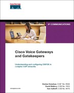
Codec Complexity
Codec complexity groups the various codecs into three categories based on the amount of DSP processing that is required to support the particular codec. Codecs are classified as low, medium, or high complexity. Table 14-2 shows the codecs and features that each complexity level supports.
The gateway determines how many voice calls each DSP can terminate based on codec complexity. If the codec complexity is set to medium, the number of voice ports that can be terminated per DSP is higher than if the codec complexity is set to high.
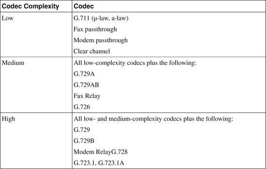
Voice cards that do not have C5510 DSPs can be configured only for medium or high complexity. Voice cards that are equipped with C5510 DSPs have an additional complexity option called flex complexity. Setting the codec complexity to medium or high sets the number of voice terminations per DSP to a static number. Flex complexity allows a variable number of calls per DSP based on runtime calculations. Flex complexity is the default for voice cards that have C5510 DSPs. This configuration allows the DSPs to support the maximum number of voice calls but introduces the possibility of oversubscribing the DSP resources.
Configuring Codec Complexity
You configure codec complexity by using the codec complexity command under voice-card configuration mode, as shown in Examples 14-6 and 14-7.
Example 14-6. Configuring Codec Complexity (C549)
!
! 3725 with NM-HDV in slot 0
!
Gateway#config terminal
Gateway(config)#voice-card 0
Gateway(config-voicecard)#codec complexity ?
high Set codec complexity high. High complexity, lower call density.
medium Set codec complexity medium. Mid range complexity and call density.
<cr>
Gateway(config-voicecard)#end
Gateway#
Example 14-7. Configuring Codec Complexity (C5510)
!
! 2811 with PVDM2-16 installed on main board.
!
GW_2811#config terminal
Enter configuration commands, one per line. End with CNTL/Z.
GW_2811(config)#voice-card 0
GW_2811(config-voicecard)#codec complexity ?
flex Set codec complexity Flex. Flex complexity, higher call density.
high Set codec complexity high. High complexity, lower call density.
medium Set codec complexity medium. Mid range complexity and call density.
GW_2811(config-voicecard)#end
GW_2811#
Note
To simplify DSP engineering, it is recommended that you set all voice cards in a gateway to the same codec complexity.
You should set codec complexity before you allocate DSPs. You cannot change codec complexity if the DSP is allocated to a voice port. If you need to change something after you have allocated the voice ports, you must remove the voice ports. This also removes the port configuration in the corresponding plain old telephone service (POTS) dial peers.
PVDMs support medium and high complexity, with medium complexity being the default. PVDM2s support medium, high, and flex complexity, with flex being the default.
Flex Complexity
Flex complexity allows a mix of low-, medium-, and high-complexity calls to be supported. This enables more calls to be supported when multiple codecs are in use. The risk is that you can oversubscribe the DSPs if more high-complexity codecs are used than the DSPs can support. If the DSPs are oversubscribed, calls will be connected, but no audio path will exist when all available DSP channels are in use.
Note
Low complexity is not configurable. You must configure flex complexity to enable the DSP to terminate additional low-complexity calls.
Table 14-3 lists the number of voice calls that each DSP can terminate per codec complexity.
Table 14-3. Number of Voice Calls Supported by DSP Type
DSP Sharing
The “DSP sharing” and “DSP farming” terms are sometimes used interchangeably in Cisco documentation. Because the Cisco IOS dspfarm command is used for both DSP sharing and DSP farming, people are confused about what these functions are. The DSP farming term was originally used to describe using DSPs as media resources for CallManager. DSP sharing allows C5510 DSPs to terminate a voice call from a voice port that is located in another hardware slot. This can reduce the possibility of oversubscription when using flex complexity. It can also make it easier to add DSPs to an existing gateway. It is physically much easier to add PVDM2s to an NM-HDV2 than it is to add them to the main board of an ISR.
DSP sharing has the following rules and definitions:
• A local DSP is on the same voice card as the voice port.
• A remote DSP is on a different voice card than the voice port.
• The DSPs on the main board of an ISR are local to the High-Performance WAN Interface Card (HWIC) and Extension Voice Module (EVM) slots and are remote to the NM slots.
• DSP sharing supports only voice termination—not transcoding.
• DSP sharing is supported on T1/E1 interfaces only.
• DSP sharing is supported on PVDM2s that are installed on the main board of 2800 and 3800 ISRs.
• DSP sharing is supported on NM-HDV2s that are installed in a 2800, 3700, or 3800 router.
• All voice cards that share DSPs must have synchronized clocks.
• You should configure all voice cards that share DSPs for the same complexity.
When you enable DSP sharing, voice cards “export” their DSPs so that another voice card can “import” the resource. When a call comes in a T1 or E1 voice port, the gateway must allocate a DSP for the call. If no local DSP is available for the call, the gateway searches for a remote DSP. The search begins with the DSPs in slot 0 and progresses through the configured voice cards. After the gateway allocates a remote DSP, the DSP remains allocated for the duration of the call, even if a local DSP becomes available.
Enabling DSP Sharing
To enable DSP sharing, you must configure at least one voice card to export its DSPs. All voice cards can import DSPs by default. DSP sharing is enabled with the dspfarm command in voice-card configuration. Example 14-8 illustrates the enabling of DSP sharing on a 2811 ISR with a PVDM2-16 installed on the main board and NM-HDV2 in slot 1. With this configuration, the DSPs on the main board are exported, allowing them to be allocated to voice calls arriving on a T1 or E1 port in the NM-HDV2. The DSPs in the NM-HDV2 are not being exported in this example.
Note
The DSPs that are installed on the main board of an ISR are configured under voice-card 0.
Example 14-8. Enabling DSP Sharing
GW_2811#config terminal
GW_2811(config)#network-clock-participate wic 2
GW_2811(config)#network-clock-participate slot 1
GW_2811(config)#voice-card 0
GW_2811(config-voicecard)#dspfarm
GW_2811(config-voicecard)#end
GW_2811#
Although DSP sharing can reduce the possibility of DSP oversubscription, it does not eliminate it. To ensure that sufficient DSP resources are always available, configure either medium or high complexity and provide sufficient local DSPs to terminate all possible voice calls.
Transcoding and MTP Resources
You can configure transcoding on the following devices:
• WS-X6608-T1/E1
• WS-SVC-CMM-ACT
• PVDM installed in NM-HDV
• PVDM2s installed in NM-HDV2
• PVDM2s installed in ISRs
• 1751/1760
Transcoding on the C549 DSP is not based on codec complexity. Each C549 DSP on a PVDM-12 supports four transcoding sessions. In the 1751/1760 gateways, two transcoding sessions are supported per DSP. Codec complexity does impact the C5510 DSP. The transcoding capabilities of the C5510 DSP are the same as the voice termination capabilities.
Table 14-4 lists the number of transcoding sessions that each DSP supports.
Table 14-4. Transcoding Session Capacities

Note
It is only possible to support 16 transcoding sessions when you are transcoding between two low-complexity codecs. Because this situation is rare, the practical maximum number of transcoding sessions per DSP is 8.
Software-based MTPs can support two voice streams with the same packetization rates. If the voice streams use different packetization rates, a DSP is required. The number of software-based MTP sessions is CPU bound and varies per router platform. You can configure only the C5510 DSP to provide hardware-based MTP services. Each DSP can support 16 MTP sessions. If a call requires MTP services and no MTP is configured, a transcoder is used if available.
Conference Bridge Resources
You need to consider only one factor when calculating conference bridge DSP requirements: the number of conferences required. Many documents on Cisco.com list only a maximum number of conference participants derived by multiplying the number of conferences by the maximum participants per conference. This leads to much confusion as to the actual capabilities of the DSPs. For example, the C5510 supports two mixed-mode conferences with up to eight participants each. Therefore, it is technically accurate to say that the C5510 supports 16 conference participants. When only the absolute maximum number of participants is listed, many people infer that you could have one conference with 16 participants or four conferences with 4 participants. When you are determining the number of DSPs required, only the number of conferences matters. The number of participants per conference is not relevant.
Note
Conferences cannot span a DSP. The maximum number of conferences per DSP and the maximum participants per conference are independent of each other.
Table 14-5 lists the conference capabilities of the various platforms, per DSP. The maximum number of conferences supported on a single Cisco IOS gateway is 50. This is because of CPU and I/O limitations.
Table 14-5. Conference Bridge Capacities
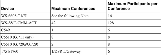
Note
The WS-X6608 module does not follow the same rules for calculating DSP requirements as the IOS-based gateways. Each port on the 6608 can support up to 32 G.711/G.723 conference participants or 24 G.729 conference participants. The number of conferences per port is not a limitation, but there can be no more than 16 participants in a single conference.
Configuring DSP Resources
Configuring a DSP to provide transcoding or conferencing resources is often referred to as DSP farming. As noted earlier, this term is also sometimes applied to DSP sharing because the command-line interface (CLI) dspfarm command is used to configure both applications. Because the term DSP farming is somewhat ambiguous, it is preferable to explicitly state which of the features you are referring to.
The configuration is similar for transcoding and conference bridging but is significantly different for C549 DSPs versus C5510 DSPs. To distinguish between the DSP types, Cisco refers to the C5510 DSPs as “Cisco IOS Enhanced Transcoding and Conferencing” DSPs.
Note
A gateway might have both C549 and C5510 DSPs installed. If this is the case, you can register only one type of DSP with CallManager. You can use both DSP types for voice termination.
Configuring Transcoding and Conferencing (C549)
To configure transcoding and conferencing on an NM-HDV, follow these steps:
Step 1. Set the interface used for Skinny Client Control Protocol (SCCP).
Gateway(config)#sccp local interface
The IP address of the configured interface is used to register with CallManager. For C549 DSPs, the MAC address of the physical interface is used for the device name. Transcoders will use the device name MTPxxxxxxxxxxxx, and Conference bridges will use the device name CFBxxxxxxxxxxxx, where xxxxxxxxxxxx is the MAC address.
Step 2. Configure the CallManager address.
Gateway(config)#sccp ccm ipaddr [priority priority-level]
The default priority level is 1. You can configure up to three redundant CallManagers by using the priority option.
Step 3. Enable SCCP.
Gateway(config)#sccp
You must set the sccp local interface before you enter the sccp command. When you enter the sccp command, the gateway initiates the registration process with CallManager.
Step 4. Configure the voice card to support transcoding and conferencing.
Gateway(config-voicecard)#dsp services dspfarm
Step 5. Set the number of transcoder and conference sessions.
Gateway(config)#dspfarm transcoder maximum sessions number
Gateway(config)#dspfarm confbridge maximum sessions number
Step 6. Enable DSP farming.
Gateway(config)#dspfarm
Step 7. Configure the transcoder and conference bridge resources in CallManager.
After you complete these steps, the gateway attempts to register with the configured CallManager using a device ID of the interface MAC address preceded by “MTP” for a transcoder resource and “CFB” for a conference resource.
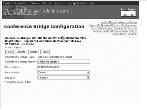
Example 14-9 illustrates configuration of an NM-HDV installed in a 3725 to support both transcoding and conferencing. Figures 14-2 and 14-3 show the associated CallManager configurations.
Example 14-9. Configuring Transcoding and Conferencing on an NM-HDV
Gateway#config terminal
Enter configuration commands, one per line. End with CNTL/Z.
Gateway(config)#sccp local vlan20
Gateway(config)#sccp ccm 10.1.5.2 priority 1
Gateway(config)#sccp ccm 10.1.5.3 priority 2
Gateway(config)#sccp
Gateway(config)#voice-card 1
Gateway(config-voicecard)#dsp services dspfarm
Gateway(config-voicecard)#exit
Gateway(config)#dspfarm transcoder maximum sessions ?
<1-48> Specify the maximum transcoding sessions value
Gateway(config)#dspfarm transcoder maximum sessions 4
Gateway(config)#dspfarm confbridge maximum sessions ?
<1-11> Specify the maximum conferencing sessions value
Gateway(config)#dspfarm confbridge maximum sessions 1
Gateway(config)#dspfarm
Gateway(config)#end
Gateway#
*Apr 18 16:50:00.647: %SYS-5-CONFIG_I: Configured from console by console
*Apr 18 16:50:02.039: %DSPRM-5-UPDOWN: DSP 3 in slot 1, changed state to up
*Apr 18 16:50:02.059: %DSPRM-5-UPDOWN: DSP 4 in slot 1, changed state to up
*Apr 18 16:50:02.139: DSPFARM all DSPs are UP with DSPFARM FW. Informed DSPFARM
!
Gateway#show dspfarm all
DSPFARM Configuration Information:
Admin State: UP, Oper Status: ACTIVE - Cause code: NONE
Transcoding Sessions: 4(Avail: 4), Conferencing Sessions: 1 (Avail: 1)
Trans sessions for mixed-mode conf: 0 (Avail: 0), RTP Timeout: 600
Connection check interval 600 Codec G729 VAD: ENABLED
Total number of active session(s) 0, and connection(s) 0
SLOT DSP CHNL STATUS USE TYPE SESS-ID CONN-ID PKTS-RXED PKTS-TXED
1 3 1 UP FREE conf - - - -
1 3 2 UP FREE conf - - - -
1 3 3 UP FREE conf - - - -
1 3 4 UP FREE conf - - - -
1 3 5 UP FREE conf - - - -
1 3 6 UP FREE conf - - - -
1 4 1 UP FREE xcode - - - -
1 4 2 UP FREE xcode - - - -
1 4 3 UP FREE xcode - - - -
1 4 4 UP FREE xcode - - - -
1 4 5 UP FREE xcode - - - -
1 4 6 UP FREE xcode - - - -
1 4 7 UP FREE xcode - - - -
1 4 8 UP FREE xcode - - - -
Total number of DSPFARM DSP channel(s) 14
!
! Show interface to obtain mac address
!
Gateway#show interface vlan20
Vlan20 is up, line protocol is up
Hardware is EtherSVI, address is 0007.b35b.d890 (bia 0007.b35b.d890)
Internet address is 10.2.20.1/24
MTU 1500 bytes, BW 100000 Kbit, DLY 1000000 usec,
reliability 255/255, txload 1/255, rxload 1/255
Encapsulation ARPA, loopback not set
ARP type: ARPA, ARP Timeout 04:00:00
Last input never, output never, output hang never
Last clearing of "show interface" counters never
Input queue: 0/75/0/0 (size/max/drops/flushes); Total output drops: 0
Queueing strategy: fifo
Output queue: 0/40 (size/max)
5 minute input rate 0 bits/sec, 0 packets/sec
5 minute output rate 0 bits/sec, 0 packets/sec
0 packets input, 0 bytes, 0 no buffer
Received 0 broadcasts, 0 runts, 0 giants, 0 throttles
0 input errors, 0 CRC, 0 frame, 0 overrun, 0 ignored
100 packets output, 7403 bytes, 0 underruns
0 output errors, 1 interface resets
0 output buffer failures, 0 output buffers swapped out
Gateway#
Figure 14-2. CallManager IOS Transcoder Configuration
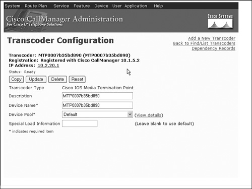
Figure 14-3. CallManager IOS Conference Bridge Configuration
Configuring Enhanced Transcoding and Conferencing (C5510)
One of the features of Enhanced Transcoding and Conferencing is the ability to create multiple profiles. Profiles allow more granular control of resources and enable a gateway to register resources with multiple CallManager groups. To configure an NM-HDV2 or ISR to register with a CallManager, follow these steps:
Step 1. Set the interface used for SCCP.
GW_2811(config)#sccp local interface
For Enhanced Transcoding and Conferencing, this command only determines which IP address CallManager will use to communicate with the gateway. The device name(s) are defined in a later step.
Step 2. Configure the CallManager addresses.
GW_2811(config)#sccp ccm ipaddr identifier identifier [version ccm
version]
Each CallManager that the gateway will register with must be configured with a unique identifier. In a later step, one or more CallManager groups will be created. You will associate the CallManager identifiers that you create here with a CallManager group and assign them a priority for registration.
Specifying the CallManager version is optional but should be set to avoid registration issues.
Step 3. Initialize SCCP.
GW_2811(config)#sccp
Step 4. Configure the voice card to support transcoding and conferencing.
GW_2811(config)#voice-card 0
GW_2811(config-voicecard)#dsp services dspfarm
Step 5. Create a DSP farm profile for transcoding.
GW_2811(config)#dspfarm profile profile transcoder
GW_2811(config-dsp-profile)#associate application sccp
GW_2811(config-dsp-profile)#maximum sessions number
GW_2811(config-dsp-profile)#no shutdown
With Enhanced Transcoding and Conferencing, you create one or more profiles for each service type. You can associate each profile with a CallManager group. The profiles are always associated with the application sccp.
Step 6. Create a DSP farm profile for conferencing.
GW_2811(config)#dspfarm profile profile conference
GW_2811(config-dsp-profile)#associate application sccp
GW_2811(config-dsp-profile)#maximum sessions sessions
GW_2811(config-dsp-profile)#no shutdown
Step 7. Create a DSP farm profile for MTP.
GW_2811(config)#dspfarm profile profile mtp
GW_2811(config-dsp-profile)#associate application sccp
GW_2811(config-dsp-profile)#maximum sessions {hardware|software}
sessions
GW_2811(config-dsp-profile)#no shutdown
You can configure software MTPs without enabling DSP services on the voice-card, even if no voice card is installed in the router.
Step 8. Associate profiles with CallManager groups.
GW_2811(config)#sccp ccm group number
GW_2811(config-sccp-ccm)#associate ccm identifier priority priority
GW_2811(config-sccp-ccm)#associate profile profile register device-name
GW_2811(config-sccp-ccm)#bind interface interface
You can associate multiple profiles with a CallManager group. Each profile is assigned a unique device-name between 6 and 16 characters long, which is used to register with CallManager. The device-name must be unique to the ccm group.
Step 9. Define the resources in CallManager.
Example 14-10 illustrates the configuration of a 2811 with two PVDM2-16s installed on the main board to support transcoding, conferencing, and MTP resources. Figures 14-4, 14-5, and 14-6 show the associated CallManager configurations.
Example 14-10. Configuring Transcoding and Conferencing on a PVDM2
GW_2811#config terminal
Enter configuration commands, one per line. End with CNTL/Z.
GW_2811(config)#sccp local vlan5
GW_2811(config)#sccp ccm 10.1.5.2 identifier 1 version 4.1
GW_2811(config)#sccp ccm 10.1.5.3 identifier 2 version 4.1
GW_2811(config)#sccp
GW_2811(config)#voice-card 0
GW_2811(config-voicecard)#dsp services dspfarm
GW_2811(config-voicecard)#exit
GW_2811(config)#dspfarm profile 1 transcode
GW_2811(config-dspfarm-profile)#associate application sccp
GW_2811(config-dspfarm-profile)#maximum sessions ?
<1-15> Number of sessions assigned to this profile
GW_2811(config-dspfarm-profile)#maximum sessions 4
GW_2811(config-dspfarm-profile)#no shutdown
GW_2811(config-dspfarm-profile)#exit
GW_2811(config)#dsp profile 1 conference
Profile id 1 is being used for service TRANSCODING
please select a different profile id
GW_2811(config)#dsp profile 2 conference
GW_2811(config-dspfarm-profile)#associate application sccp
GW_2811(config-dspfarm-profile)#maximum sessions ?
<1-2> Number of sessions assigned to this profile
GW_2811(config-dspfarm-profile)#maximum sessions 2
GW_2811(config-dspfarm-profile)#no shutdown
GW_2811(config-dspfarm-profile)#exit
GW_2811(config)#dspfarm profile 3 mtp
GW_2811(config-dspfarm-profile)#associate application sccp
GW_2811(config-dspfarm-profile)#maximum sessions hardware ?
<1-8> Number of sessions assigned to this profile
GW_2811(config-dspfarm-profile)#maximum sessions hardware 4
GW_2811(config-dspfarm-profile)#maximum sessions software ?
<1-500> Number of sessions assigned to this profile
GW_2811(config-dspfarm-profile)#maximum sessions software 10
GW_2811(config-dspfarm-profile)#no shutdown
GW_2811(config-dspfarm-profile)#exit
GW_2811(config)#sccp ccm group 10
GW_2811(config-sccp-ccm)#associate ccm 1 priority 1
GW_2811(config-sccp-ccm)#associate ccm 2 priority 2
GW_2811(config-sccp-ccm)#associate profile 1 register XCD123456
GW_2811(config-sccp-ccm)#associate profile 2 register CFB123456
GW_2811(config-sccp-ccm)#associate profile 3 register MTP123456
GW_2811(config-sccp-ccm)#bind interface vlan5
GW_2811(config-sccp-ccm)#^Z
GW_2811#show dspfarm all
Dspfarm Profile Configuration
Profile ID = 1, Service = TRANSCODING, Resource ID = 1
Profile Description :
Profile Admin State : UP
Profile Operation State : ACTIVE
Application : SCCP Status : ASSOCIATED
Resource Provider : FLEX_DSPRM Status : UP
Number of Resource Configured : 4
Number of Resource Available : 4
Codec Configuration
Codec : g711ulaw, Maximum Packetization Period : 30
Codec : g711alaw, Maximum Packetization Period : 30
Codec : g729ar8, Maximum Packetization Period : 60
Codec : g729abr8, Maximum Packetization Period : 60
Codec : gsmfr, Maximum Packetization Period : 20
Dspfarm Profile Configuration
Profile ID = 2, Service = CONFERENCING, Resource ID = 2
Profile Description :
Profile Admin State : UP
Profile Operation State : ACTIVE
Application : SCCP Status : ASSOCIATED
Resource Provider : FLEX_DSPRM Status : UP
Number of Resource Configured : 2
Number of Resource Available : 2
Codec Configuration
Codec : g711ulaw, Maximum Packetization Period : 30 , Transcoder: Not Required
Codec : g711alaw, Maximum Packetization Period : 30 , Transcoder: Not Required
Codec : g729ar8, Maximum Packetization Period : 60 , Transcoder: Not Required
Codec : g729abr8, Maximum Packetization Period : 60 , Transcoder: Not Required
Codec : g729r8, Maximum Packetization Period : 60 , Transcoder: Not Required
Codec : g729br8, Maximum Packetization Period : 60 , Transcoder: Not Required
Dspfarm Profile Configuration
Profile ID = 3, Service = MTP, Resource ID = 3
Profile Description :
Profile Admin State : UP
Profile Operation State : ACTIVE
Application : SCCP Status : ASSOCIATED
Resource Provider : FLEX_DSPRM Status : UP
Number of Resource Configured : 14
Number of Resource Available : 14
Hardware Configured Resources : 4
Hardware Available Resources : 4
Software Resources : 10
Codec Configuration
Codec : g711ulaw, Maximum Packetization Period : 30
SLOT DSP VERSION STATUS CHNL USE TYPE RSC_ID BRIDGE_ID PKTS_TXED PKTS_RXED
0 1 4.4.12 UP N/A FREE xcode 1 - - -
0 1 4.4.12 UP N/A FREE xcode 1 - - -
0 1 4.4.12 UP N/A FREE xcode 1 - - -
0 1 4.4.12 UP N/A FREE xcode 1 - - -
0 1 4.4.12 UP N/A FREE mtp 3 - - -
0 1 4.4.12 UP N/A FREE mtp 3 - - -
0 1 4.4.12 UP N/A FREE mtp 3 - - -
0 1 4.4.12 UP N/A FREE mtp 3 - - -
0 5 1.0.6 UP N/A FREE conf 2 - - -
0 5 1.0.6 UP N/A FREE conf 2 - - -
Total number of DSPFARM DSP channel(s) 10
Figure 14-4. CallManager Enhanced IOS Transcoder Configuration
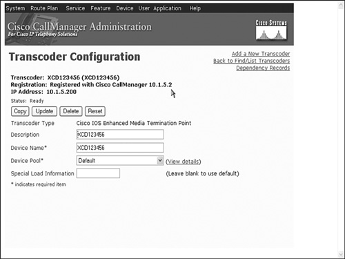
Figure 14-5. CallManager Enhanced IOS Conference Bridge Configuration

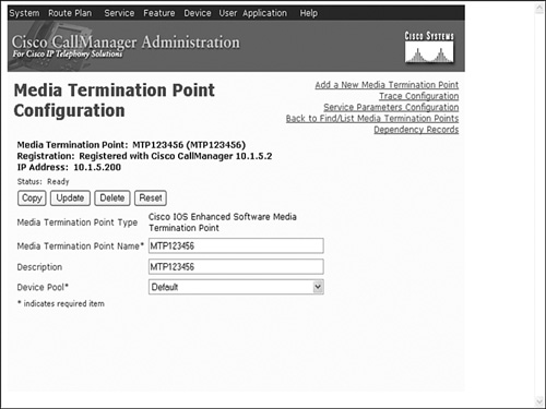
Figure 14-6. CallManager Enhanced MTP Configuration
Transcoding for CallManager Express
CME supports DSPs for transcoding. It does not support DSP-based conference bridges at this time. The configuration is similar to registering DSPs to a CallManager. The IP address used in the sccp ccm command is the IP address of the CME service. This should match the ip source-address specified under telephony-service.
After you have completed Step 6 for C549 DSPs or Step 8 for C5510 DSPs, the following steps register the transcoders to CME:
Step 1. Enter telephony-service configuration mode.
GW_2811(config)#telephony-service
Step 2. Set the maximum number of DSP farms that can be registered to CME.
GW_2811(config-telephony)#sdspfarm units number
A CME can support up to five transcoder sessions. These can be locally defined transcoders on the CME gateway or DSPs that are defined on other gateways.
Step 3. Specify the maximum number of transcoding sessions supported across all registered transcoders.
GW_2811(config-telephony)#sdspfarm transcode sessions number
This is the total number of sessions provided by all registered transcoders. Valid entries are 1 through 128.
Step 4. Specify the name of the DSP farm.
GW_2811(config-telephony)#sdspfarm tag number device-name
The device name follows the same rules as CallManager registrations. For C549 DSPs, the device-name is “MTP” plus the MAC address of the SCCP local interface. For C5510 DSPs, the device-name is specified when you associate the transcoder profile to the ccm group.
Case Study: Add DSP Resources to the Miami Gateway
Employees at the Miami location frequently conference in their supervisor when talking to customers. You have been asked to provision local DSP resources to prevent these calls from using DSP resources at headquarters.
The Miami location has a Cisco 2811 with two PVDM2-16s installed on the main board. There is a channel-associated signaling (CAS) T1 to the PSTN installed in HWIC slot 3. A VIC2-2FXO is installed in HWIC slot 0, and a VIC2-2FXS is installed in HWIC slot 1. How many simultaneous conferences can the Miami gateway support?
At the default flex complexity, 32 channels are available to support voice termination. Twenty-eight channels are required to support the four analog ports and 24 DS0s. This requires the DSPs from both PVDM2-16s. Conference bridge resources require a dedicated DSP—so the Miami gateway will not support conferences without some modification.
The best solution to this problem is to add additional PVDM2s to the gateway. The other possible solution is to reduce the number of voice calls that the router handles. Because the Miami call volume is light and consists mostly of inbound calls, you have decided to reduce the number of DS0s allocated to the outbound DS0-group and remove the analog voice ports that are not currently being used.
Example 14-11 illustrates the configuration for the Miami gateway after the voice port modifications.
Example 14-11. Configuring Conference Resources in Miami Gateway
Miami#show configuration
Building configuration...
Current configuration : 3077 bytes
!
! Unnecessary output omitted...
!
! Enable DSP services on voice-card 0
!
voice-card 0
dsp services dspfarm
!
!
interface FastEthernet0/0
no ip address
duplex auto
speed auto
!
interface FastEthernet0/0.25
encapsulation dot1Q 25
ip address 10.10.25.1 255.255.255.0
!
interface FastEthernet0/0.50
encapsulation dot1Q 50
ip address 10.10.50.1 255.255.255.0
!
interface FastEthernet0/1
no ip address
shutdown
duplex auto
speed auto
!
controller T1 0/3/0
framing esf
linecode b8zs
ds0-group 1 timeslots 1-12 type e&m-fgd
ds0-group 2 timeslots 13-16 type fgd-eana
!
ip classless
!
!
voice-port 0/3/0:1
!
voice-port 0/3/0:2
!
! Define cmm addresses
!
sccp local FastEthernet0/0.25
sccp ccm 10.1.10.10 identifier 1 version 4.1
sccp ccm 10.1.10.11 identifier 2 version 4.1
sccp
!
!Create the CCM Group
!
sccp ccm group 10
bind interface FastEthernet0/0.25
associate ccm 1 priority 1
associate profile 1 register CFB_Miami
!
!Create the Conference Bridge Profile
!
dspfarm profile 1 conference
codec g711ulaw
codec g711alaw
codec g729ar8
codec g729abr8
codec g729r8
codec g729br8
maximum sessions 2
associate application SCCP
!
!
With this configuration, the Miami gateway will attempt to register its conferencing resources with CallManager, using a device-name of “CFB_Miami.”
Review Questions
1 What is the purpose of a DSPFarm Profile?
2 When is a DSP needed for an MTP?
3 What is the default codec complexity for a C5510 DSP?
4 What is the major difference in the way C549 and C5510 DSPs handle voice termination?
5 You need to terminate 14 G.711 calls, provide transcoding for 6 G.729a to G.711 calls, and support 5 G.711 conference sessions with up to eight participants in each conference. What is the minimum number of DSPs required?
6 You need to support one mixed-mode conference with up to eight participants. How should you configure the maximum sessions under the conference profile?
7 Describe two benefits of DSP sharing.
8 Your ISR 2811 has an NM-HDV with five PVDM-12s and two PVDM2-48s installed on the main board. The NM-HDV is configured for medium complexity and has one E1 voice port. There are also two E1 voice ports in HWIC slots. What is the maximum number of G.711 conferences that you can support with the extra DSPs?