Chapter 11. Influencing Path Selection
Thus far, this book has discussed various ways to configure a gateway to ensure that your calls go through. This chapter introduces ways to control the path that calls take and to prevent calls from being placed without adequate resources to support them.
It is usually desirable to have more than one path for a call to take. Multiple paths provide redundancy in the event of a link failure or insufficient resources and sometimes are used to reduce the transport cost of a call. These paths might consist completely of Voice over IP (VoIP), or they might be a mixture of VoIP and plain old telephone service (POTS).
When you are using VoIP, keep in mind that voice is an application on the network, and voice messages are carried in IP packets. You can implement techniques to choose which VoIP dial peer is used for a call, but the IP routing structure of your network determines the path to that target IP address. This chapter talks about ways to control call routing using commands and techniques that apply to the voice application, but IP routing ultimately controls VoIP routing. VoIP traffic can be affected by router configuration such as access lists that might block a voice subnet, or policy-based routing that might send voice traffic out a different interface than the one desired. Various commands enable you to control the source IP address of voice packets; you must consider this when you are configuring policies along the entire voice path so that you avoid inadvertently blocking that traffic.
When you are planning and troubleshooting VoIP path selection, take these two levels of call routing into account. In planning, be sure that your voice calls will take the path at each hop that you want them to. When troubleshooting, test the IP path chosen through the network.
Many different ways exist to control call routing and make call admission decisions. With some methods, you make the decisions on the gateway. With others, you use a separate device. In H.323 networks, gatekeepers can control call routing; in Session Initiation Protocol (SIP) networks, proxy servers can perform that function. In Cisco Unified Communications Systems, CallManager makes call routing and admission decisions. In this chapter, you will learn about the following:
• Use of hunt groups and trunk groups
• Use of tail-end hop-off
• CAC techniques based on local gateway settings, on measurements of network performance, and on router resource availability
• Use of the IP Service Level Agreement (SLA) tool
• Use of Resource Reservation Protocol (RSVP) and the RSVP Agent
• Considerations when routing between POTS calls
Hunt Groups
One of the most straightforward ways to control call route selection on a gateway is to create hunt groups. A hunt group is a set of dial peers, all referencing the same destination pattern. You can use hunt groups to provide load balancing over multiple ports or to provide redundancy if a primary port is unusable.
You can use hunt groups with both POTS and VOIP interfaces. This section shows how to configure hunt groups for those gateway protocols that use dial peers: H.323 and SIP. You must configure hunt groups on the call agent when using MGCP gateways.
You can mix POTS and VoIP dial peers in the same hunt group. By default, a router selects which dial peer in a hunt group to use by the following criteria:
1. Longest match—This is the destination pattern that matches the most number of digits.
2. Preference value—Dial peers are chosen in order of preference.
3. Random selection—If all dial peers have the same preference, they are used in random order.
The dial-peer hunt value command gives you a fourth option—least recently used dial peer—and a way to alter the default order of the choice selection criteria. Example 11-1 shows the options that are available with the dial-peer hunt command.
Example 11-1. The dial-peer hunt Command
Shanghai-GW(config)#dial-peer hunt ?
<0-7> Dial-peer hunting choices, listed in hunting order within each choice:
0 - Longest match in phone number, explicit preference, random selection.
1 - Longest match in phone number, explicit preference, least recent use.
2 - Explicit preference, longest match in phone number, random selection.
3 - Explicit preference, longest match in phone number, least recent use.
4 - Least recent use, longest match in phone number, explicit preference.
5 - Least recent use, explicit preference, longest match in phone number.
6 - Random selection.
7 - Least recent use.
Using the preference Command
You create a hunt group by using the preference command under the dial peer configuration mode, as shown in Example 11-2. Preference values can range from 0 to 10, with the lowest number being the most preferred. Thus, a dial peer with a preference value of 1 would be used before a dial peer with a preference value of 2, all other things being equal. The default preference for dial peers is 0, which is the most preferred, or highest priority, value. If the most preferred dial peer is not available, the router tries the dial peer with the next higher preference value, and so on.
If the same preference value and destination pattern are configured on a POTS and a VoIP dial peer, the POTS dial peer is used.
Example 11-2. Configuring a Hunt Group Using Preference
!The primary dial peer uses the default preference value of 0
dial-peer voice 3400 voip
destination-pattern 34..
session target ipv4:10.6.2.10
!
!The dial peer to use if the primary is unavailable
dial-peer voice 3401 pots
destination-pattern 34..
preference 1
port 1/0:23
Using the huntstop Command
Dial peer hunting is enabled by default. If a call fails on one dial peer in a hunt group, the gateway continues hunting. The dial peer huntstop command stops the gateway from searching for other matches if the call fails on that dial peer. One use for this is a gateway with dial peers using an explicit destination pattern (such as 221.) pointing to one set of ports, and a dial peer using a less explicit destination pattern (such as 2...) pointing to another port. If you do not want the router to use the less explicit dial peer, add the huntstop command under the dial peer where you want the router to stop hunting, as shown in Example 11-3. Note the huntstop command under dial peer 2212. To re-enable hunting, use no huntstop.
Example 11-3. Using the huntstop Command
!The preferred dial peer for calls to 221x
dial-peer voice 2211 pots
preference 1
destination-pattern 221.
forward-digits all
port 0/0/0
!
!The secondary dial peer for calls to 221x
dial-peer voice 2212 pots
preference 2
huntstop
destination-pattern 221.
forward-digits all
port 0/0/1
!
!A less explicit dial peer that should not be used for calls to 221x
dial-peer voice 2200 pots
destination-pattern 2...
forward-digits all
preference 3
port 1/0:23
Using Digit Manipulation
When you are using alternate dial peers, you might have to adjust the call information that is sent. Various digit manipulation techniques are available to do this. See Chapter 10, “Digit Manipulation,” for detailed information on digit manipulation techniques and commands.
Figure 11-1 illustrates some typical situations in which you might need digit manipulation. The figure shows a simple network with two sites connected over an IP network. If the IP WAN is unavailable, each gateway is configured to reroute calls over the public switched telephone network (PSTN). The remote site on each gateway has a primary VoIP and a secondary POTS dial peer.
Figure 11-1. Using Digit Manipulation with Hunt Groups
Potential problems with this voice network include the following issues. Example 11-4 shows a configuration that uses digit manipulation to solve these problems.
• A VoIP dial peer transmits all digits by default, but a POTS dial peer truncates digits that match the destination pattern. If a POTS dial peer serves as backup to a VoIP dial peer, you need to specify the number of digits to send. In networks in which the entire phone number is dialed, this can be as simple as coding forward-digits all under the POTS dial peer. In Figure 11-1, a site code of 3 is used for Boise. This should not be sent to the terminating gateway. In Example 11-4, the VoIP dial peer 1112 of the Miami router has a translation profile that allows just the last four digits of the dialed number to be transmitted.
• VoIP dial peers usually connect internal networks, so users usually do not dial the entire destination telephone number. If the alternate dial peer routes the call over the PSTN, you need to add information that the PSTN needs to route the call, such as long-distance code, area code, and prefix. In Figure 11-1, the POTS dial peer strips all but the last two digits, so a prefix command is coded on the Miami router under POTS dial peer 202 to add the long-distance access number (1), the Boise area code (208), and the next five digits of the phone number (55501). The site code of 3 is not sent. Similarly, on the POTS dial peer 202 of the Boise router, the long-distance access code (1), the Miami area code (301), and the next five digits of the phone number (55501) are prefixed. The site code of 2 is stripped.
• You might need to manipulate the called number on the terminating gateway. The Boise gateway expects to route calls to its LAN phones based on a four-digit DNIS. If the PSTN sends more digits, you need to strip some digits from the incoming called number. You might also want to manipulate the calling number to provide the caller ID that users expect to see. In Figure 11-1, the PSTN sends a ten-digit dialed number identification service (DNIS) to Boise. Example 11-4 shows that the Boise gateway translates that to just the last four digits under POTS dial peer 202.
Example 11-4. Configuring Digit Manipulation with Hunt Groups
!Miami Router Configuration
!Creates a translation rule to remove the site code
voice translation-rule 3
rule 1 /^301/ /01/
!
!Creates the translation profile associated with Rule 3
voice translation-profile BOISE-VOIP
translate called 3
!
!Primary dial peer, pointing to Boise router, site code is removed, four digits sent
dial-peer voice 1112 voip
translation-profile outgoing BOISE-VOIP
preference 1
destination-pattern 301..
session target ipv4:10.20.25.1
!
!Backup dial peer, sends calls to PSTN and adds necessary digits
dial-peer voice 202 pots
preference 2
destination-pattern 301,,
direct-inward-dial
prefix 120855501
port 1/0:23
!Boise Router Configuration
!
!Creates a translation rule to remove the site code
voice translation-rule 2
rule 1 /^201/ /01/
!
!Creates a translation rule to remove the extra digits sent by the PSTN
voice translation-rule 22
rule 1 /^208555/ //
!
!Creates a translation profile associated with Rule 2
voice translation-profile MIAMI-VOIP
translate called 2
!
!
!Creates a translation profile associated with Rule 22
voice translation-profile MIAMI-POTS
translate called 22
!
!Primary dial peer, pointing to Miami router, site code is removed, four digits sent
dial-peer voice 1112 voip
translation-profile outgoing MIAMI-VOIP
preference 1
destination-pattern 201..
session target ipv4:10.10.25.1
!
!Backup dial peer, sends call to PSTN, adds necessary digits to outbound calls
dial-peer voice 202 pots
!Translation profile removes all but four digits on incoming calls from Miami
translation-profile incoming MIAMI-POTS
preference 2
destination-pattern 201,,
direct-inward-dial
prefix 130155501
port 1/0:23
Using Trunk Groups
BRI, PRI, and CAS interfaces and FXO, FXO, and Ear and Mouth (E&M) voice ports can be combined into trunk groups. When you create a trunk group, you can add configuration to control path selection. Create a trunk group with the global trunk group name command. This puts you in trunk group configuration mode. You can then add commands that will apply to all the circuits in the group. The max-call voice number command limits the number of incoming and outgoing calls that the trunk group will accept. By default, the least-used trunk is selected when the gateway hunts through a trunk group. You can change this with the hunt-scheme command. This command has the following options:
• least-idle [even | odd | both]—Looks for the most recently released channel.
• least-used [even | odd | both [up | down]]—Is the default hunt method for a trunk group. It looks for the trunk member with the most unused channels.
• longest-idle [even | odd | both]—Looks for the trunk member that has been idle the longest amount of time.
• Random—Chooses a trunk member at random and a random channel within that trunk member.
• round-robin [even | odd | both[up | down]]—Looks at trunk group members in a round robin fashion, one after the other.
• sequential [even | odd | both[up | down]]—Always starts looking for a free channel with the highest priority trunk.
In each command, even selects even-numbered channels within a trunk member first, odd selects odd-numbered channels within a trunk member first, and both considers all channels for selection. The option up hunts through the channels in ascending order, whereas the option down hunts through them in descending order.
Add an interface or voice port to a hunt group with the trunk group name [preference] command. The preference value indicates the priority of the trunk within the group. A lower preference value equates to a higher priority trunk. You can then assign multiple trunk groups to dial peers, with a priority value to determine their use by the dial peer.
Tail-End Hop-Off
Tail-End Hop-Off (TEHO) allows a company to reduce its long-distance toll charges. When remotes sites are connected by an IP WAN, you can route calls that are bound to those cities—and those sites—over the WAN. The terminating gateway then routes them out to the PSTN as a local call. This sounds like a good idea in theory, but it can be complex in practice.
You need a separate dial peer for each area code/prefix combination in each remote location. Large cities have many prefixes and might have several area codes also. Small cities or regions might have some prefixes within the same area code that are local calls, and some that are long-distance calls. You might need a gatekeeper for an extensive TEHO implementation.
Regulatory issues might curtail the use of TEHO, also. TEHO results in a loss of revenue for telecommunications companies, so some countries regulate calls carried across country or regional borders. Careful planning and research on the most recent laws concerning mixed VoIP and PSTN calls is necessary before implementing TEHO in your network.
Example 11-5 shows a possible TEHO configuration for the network shown in Figure 11-1. In this example, the Miami office implements TEHO for calls to the Boise area code 208.
For purposes of the example, it is assumed that prefix 555 in area code 208 is a local call from the Boise office and that Boise uses ten-digit local dialing.
Example 11-5. TEHO Configuration
!Miami Router Configuration
!
!The primary dial peer for TEHO; calls go across the IP WAN
dial-peer voice 2081 voip
preference 1
destination-pattern 9208555....
session target ipv4:10.20.25.1
!
!Backup dial peer; calls go to the PSTN
dial-peer voice 2082 pots
preference 2
destination-pattern 9208555....
prefix 1208555
port 1/0:23
!Boise Router Configuration
!
!Dial peer that sends local calls to the PSTN
dial-peer voice 208 pots
destination-pattern 9208555....
prefix 208555
port 1/0:23
Call Admission Control
Call admission control (CAC) is used to protect the quality of your voice calls by preventing call completion if not enough resources are available to support it. CAC is needed over an IP WAN because IP does not possess the ability of the time-division multiplexing (TDM) world to meter calls. When a POTS line is in use, or a DS0 in a PRI is in use, the gateway cannot use that link for additional calls. But nothing is inherent in an IP interface that stops more packets from attempting to use it.
It is generally recognized that a voice network needs quality of service (QoS) mechanisms. However, QoS just protects voice from interference by data traffic. It does not protect voice from voice. Consider a router that is configured with a low-latency queue (LLQ) for voice, and that queue is allocated enough bandwidth for ten calls. Then suppose that an eleventh call is placed. QoS would not prevent the router from sending that call. Instead, the queue would fill up faster, and voice packets would start to be dropped. This would affect the quality of all 11 calls, not just the extra one.
CAC techniques attempt to remedy this. If CAC were implemented, the eleventh call could be rerouted to another VoIP dial peer or out to the PSTN. If the call came from a TDM switch, it could be returned to that switch for handling.
Many different types of CAC exist, and each uses different methods to decide whether to allow a call. CAC techniques can be divided into three categories:
• Local
• Measurement based
• Resource based
This section discusses each CAC type to help you decide which ones to use in your network. You can deploy multiple types of CAC mechanisms on the same gateway. If so, the gateway goes through a sequence of checks against the CAC types. If any of these tests rejects the call, the process ends at that point, and no further checking is done.
When multiple CAC mechanisms are configured, the selection process follows these steps:
Step 1. The gateway checks for the max-conn configuration on the outbound dial peer.
If the limit has been reached, the call is rejected. If no max-conn is configured, or the limit has not been reached, the router goes to Step 2.
Step 2. The router checks for CAC mechanisms based on local system resources, such as CPU use.
If these resources are not configured, or if the test succeeds, the router goes to Step 3.
Step 3. If a gatekeeper is used, and it is configured to do CAC based on bandwidth, the gatekeeper is checked.
If this test succeeds, or no gatekeeper CAC is used, the router proceeds to Step 4.
Step 4. If RSVP is configured, an RSVP reservation is attempted. When RSVP is used, this is the last test.
If the call is allowed, call setup continues. If not, the router rejects the call. Only if RSVP is not configured does the router go to Step 5.
Step 5. Any CAC mechanism that use probes to measure network availability is now checked.
This is the last test. If the call is allowed, setup proceeds. If not, it is rejected.
Network components other than a gateway can also make CAC decisions. In a network that uses Cisco CallManager, it is the CallManager, not the gateway, that usually makes CAC decisions. You can configure CallManagers with locations. You assign phones and other devices to a location when you add them to CallManager. Configure CallManager with a maximum bandwidth for audio and for video calls for each location. It then allows calls to or from that location across the WAN only if sufficient bandwidth is available. In addition, you can configure CallManager to use RSVP for some locations and not for others.
You can also configure gatekeepers to do CAC. Gatekeepers base their decisions either on bandwidth between zones or gateway resource availability. The section “Resource-Based CAC Mechanisms” has more information. SIP proxy servers can make CAC decisions in SIP networks.
Local CAC Mechanisms
Local CAC mechanisms are configured on the outgoing gateway, and they are aware only of local conditions. They base their call routing decisions on either the number of current calls or the state of the interface to which calls are routed. If that works for your network, you do not need to introduce the extra complexity of other techniques. Local CAC mechanisms are relatively easy to configure, and they have low overhead.
Physical DS0 Limitation
A straightforward way to limit the number of calls over the IP WAN is to limit the number of internal calls coming to the gateway. A router that is connected to a PBX with six POTS lines will never have more than six calls active over the WAN. If the router is connected to the PBX with a PRI, the number of timeslots can be configured. When all the DS0 channels are in use, the PBX is responsible for rerouting outbound calls to the PSTN.
Maximum Connections
You can configure the number of calls allowed per dial peer by using the max-conn number command under dial-peer configuration mode. The default is to allow an unlimited number of calls. In Example 11-6, five connections are allowed to phone numbers beginning with 11.
Example 11-6. Configuring the Maximum Connections for a Dial Peer
VoiceGW(config)#dial-peer voice 11 voip
VoiceGW(config-dial-peer)#destination-pattern 11T
VoiceGW(config-dial-peer)#max-conn 5
Keep in mind that this is just for the specific dial peer, not for the interface or the network as a whole. Limiting connections could be useful in a network with a few sites having a small number of phones and low WAN bandwidth. You must configure a separate dial peer for each remote site. The number of calls allowed on the egress interface is equal to the sum of all the connections that are allowed. The max-conn command helps limit the bandwidth use of the gateway WAN interface, and it prevents remote sites from being overwhelmed by calls that they will deny. However, it does not adjust to topology changes or WAN usage, and it works only in gateways that use dial peers.
Local Voice Busyout
Local voice busyout (LVBO) is used on a gateway that is connected to a PBX and an IP WAN. It tells the router to watch an interface, and if that interface goes down, the router busies out the ports or trunks to the PBX. This appears to the PBX as if the ports are off-hook. Multiple interfaces can be tracked; all must be down before the router busies out a voice port.
You should only use LVBO when the gateway is connected to a PBX, and the PBX connects to the PSTN. The PBX can then reroute internal callers to the PSTN instead of over the IP WAN. If you use it on a router that is a PSTN gateway, the PSTN interfaces are taken out of service, which stops external calls from coming into the network. That is usually not the desired result.
Note
LVBO tracks only the up or down status of an interface, not its usage.
LVBO can monitor LAN, WAN, and virtual interfaces and subinterfaces. You configure LVBO under the voice port configuration mode, as shown in Example 11-7.
Example 11-7. Configuring LVBO
VoiceGW(config)#voice-port 0/0/0
VoiceGW(config-voiceport)#busyout monitor interface fa 2/0
VoiceGW(config-voiceport)#busyout monitor interface atm 1/0.10
You can add an additional command, busyout action graceful, to the voice port configuration. The router then busies out the port only after active calls hang up. In H.323 networks that use gatekeepers, you can monitor the gatekeeper, and busy out ports if the gateway is unreachable, by using the busyout monitor gatekeeper command.
Measurement-Based CAC Mechanisms
Measurement-based CAC mechanisms look beyond the local router, into the network between the originating and terminating gateways. They attempt to measure network congestion by sending probes through the network to measure latency, delay, and jitter. The outgoing gateway uses this information to permit or deny calls. The router can reroute calls when network delay or packet loss is too high, or it can busy out voice ports so that they will not be used. The functionality to send and respond to probes is part of the Cisco IOS. In Cisco IOS releases after 12.3(14)T, the feature is called IP Service Level Agreement (IP SLA). IP SLA is an extension to the Service Assurance Agent (SAA) and Response Time Reporter (RTR) features that are present in Cisco IOS versions prior to 12.3(14)T. New commands using the ip sla syntax have been released beginning with Cisco IOS version 12.4.
IP SLA
IP SLA is a network monitoring and management feature that is part of the Cisco IOS. It enables you to proactively monitor and measure network performance for specific applications, not just in general. IP SLA works by sending probes to the IP address of a target device, which responds to them. When a Cisco router is the target, you can configure it as an IP SLA responder and return more accurate information. For instance, an IP SLA responder adds timestamps to the response packets so that router processing delay is not counted as part of the round-trip time. You can configure an IP SLA responder to listen only on a certain port for probe packets. You can use MD5 authentication between IP SLA sources and responders for enhanced security.
You can schedule IP SLA probes to run at a certain time, or you can run them at periodic intervals. These probes can emulate many different types of network traffic, such as FTP, Dynamic Host Configuration Protocol (DHCP), and HTTP. For VoIP and CAC, typically User Datagram Protocol (UDP) and Real-Time Transport Protocol (RTP) headers are used to emulate voice traffic, measuring jitter, gatekeeper delay, post dial delay, and RTP operations. Codec can be specified for the probes, and IP SLA will send a configurable number of packets sized appropriately for the type of codec. You can set type of service (TOS) values so that the probes receive the same QoS treatment as voice.
Measurements include jitter, round-trip time, packet loss, and one-way delay. From this information, IP SLA estimates voice quality using the Calculated Planning Impairment Factor (ICPIF) and Mean Opinion Scores (MOS) described in the next section of this chapter.
You can retrieve this information from the command line with show commands, but its real usefulness lies in the ability of the router to store the results in MIBs. Then you can retrieve the information via Simple Network Management Protocol (SNMP) so that applications, such as CiscoWorks and some third-party applications, can use it. A change in network performance can trigger alerts or other types of probes to troubleshoot the problem, for instance. Companies that are considering moving to VoIP need to be sure that their network will support it, and IP SLA is one way to test that.
Calculated Planning Impairment Factor and Mean Opinion Scores
IP SLA uses the information it gathers from its probes to provide estimates of probable voice quality. If network conditions are such that voice quality will be too low, calls can be rejected or rerouted, or troubleshooting measures can be triggered. Voice quality is measured in two ways:
• ICPIF
• MOS
ICPIF is an International Telecommunications Union Telecommunication Standardization Sector (ITU-T) recommendation that attempts to objectively measure voice quality by measuring network elements that impair voice call quality. In calculating an ICPIF value, Cisco uses a formula that simplifies to icpif = idd + ie – A, where
• idd (delay impairment factor) equals one-way delay.
• ie (equipment impairment factor) equals percent of packet loss.
• A (advantage factor, sometimes called expect factor) equals a value that is meant to reflect the fact that users accept some quality degradation under certain circumstances. Cisco assumes a value of 0 for this variable, but that is configurable.
The result of this calculation is a value representing the probable voice quality of a call sent across the circuits traversed by the probe, at the moment the probe is sent. ICPIF values range between 5 and 55, and they are assigned the meanings shown in Table 11-1.

Voice quality is a fairly subjective thing. What might be adequate for one person might be intolerable for another. MOS is a rating of voice quality obtained by averaging the opinions of a wide range of listeners. Table 11-2 shows the MOS values, their meanings, and the equivalent ICPIF values.
Table 11-2. Mean Opinion Score Values

IP SLA calculates the ICPIF and MOS values, and measurement-based CAC mechanisms can use these values to allow or disallow a call. You can also configure a maximum ICPIF value for calls that a VoIP dial peer sends.
Configuring IP SLA
Begin configuring IP SLA by choosing the routers on which it will be used. If you are using it to test a network, configure it on the routers at each end of the network. If you are using it to troubleshoot a problem, you might want to test network performance between each hop. If you plan to use IP SLA as a network monitoring tool, sending probes regularly, you should be aware that the tool has a performance cost. If you need to send a lot of probes, such as at a hub site that monitors remote sites, consider using a dedicated router as the IP SLA source router. This also gives you one central location from which to gather measurements.
Enter IP SLA configuration mode with the ip sla operation-number global command. The operation-number identifies a unique IP SLA instance. From there, you can configure the type of traffic to be measured. The measurements typically of concern to voice are contained under UDP jitter commands. For UDP jitter, the minimum required command is udp-jitter {destination_IP-address | destination_hostname} {port-number}. Additional options to this command include the following:
• codec—Configures the codec type for IP SLA packets to use. When codec is specified, you can optionally configure codec-interval, codec-numpackets, and codec-size. The default interval between packets is 20 ms, the default number of packets sent is 1000, and the default size is 160 bytes for G711 and 20 bytes for G729.
• control {enable | disable}—Enables or disables the sending of IP SLA control packets from the source to the responder. It is enabled by default; disabling it results in less accurate measurements.
• interval interval—Configures the interpacket interval in milliseconds. The default is 20 ms.
• num-packets packets—Sets the number of packets to send. The default is ten.
• source-ip {ip-address | hostname}—Specifies a source IP address or hostname. Without this option, the router uses the IP address of the exit interface.
• source-port {port-number}—Configures the source port for IP SLA packets. When this option is not set, the router chooses a port.
You can also set a TOS value for the IP SLA packets. IP SLA looks at the first 4 bits of the TOS byte in the IP header, but the value of these bits is calculated as if all 8 bits were used. For instance, an IP precedence of 5 and a differentiated services code point (DSCP) value of 40 both equate to an IP SLA TOS of 160. In IP SLA jitter configuration mode, give the tos value command.
After you have configured an IP SLA operation, you can schedule it. You can have it run immediately, on a regular basis, or at some point in the future. Use the ip sla schedule operation-number [ageout seconds] [life {forever | seconds}] [start-time {hh:mm[:ss] [month day | day month] | pending | now | after hh:mm:ss}] [recurring] global command. After you have scheduled an operation, you cannot change its configuration. If you need to make changes, you must delete and re-create that operation.
To configure a router as an IP SLA responder, code the ip sla responder command in global configuration mode.
To enable MD5 authentication of IP SLA packets, complete the following steps on both the source and the responder routers:
Step 1. Create a key chain and enter key chain configuration mode with the global key chain name command.
Step 2. Create a key with the key number command.
Step 3. Create the key string with the key-string key-text command.
You can create several keys for a specific key chain, but be sure to create them in the same order on both routers. If multiple keys exist, the routers will rotate key use during their communication. After the key chain is complete, configure IP SLA to use authentication with the ip sla key-chain name global command.
Example 11-8 shows the configuration of IP SLA source (Boise) and responder (Miami) routers. The routers use MD5 authentication for the IP SLA packets. UDP jitter is being measured using a destination port of 65424 and the G729 codec. A TOS value of 176 is used, which corresponds to an IP precedence of 5, and DSCP of 46 (expedited forwarding). The probe is scheduled to run every day at 9:00 am. In the output of the show ip sla statistics command, you can see the measured round-trip time, latency, jitter, and packet loss. The calculated ICPIF and MOS values are shown in the shaded area. PSTN fallback can use these values, which is discussed in the next section.
Example 11-8. Configuring IP SLA Source and Responder
!Configure the router that will respond to the IP SLA probes
MiamiGW#conf t
Enter configuration commands, one per line. End with CNTL/Z.
MiamiGW(config)#ip sla responder
!
!Configure MD5 authentication
MiamiGW(config)#key chain IP-SLA
MiamiGW(config-keychain)#key 1
MiamiGW(config-keychain-key)#key-string cisco
!
!MiamiGW(config)#ip sla key-chain IP-SLA
!Configure the router that will originate the IP SLA probes
BoiseGW#conf t
Enter configuration commands, one per line. End with CNTL/Z.
BoiseGW(config)#ip sla 10
BoiseGW(config-ip-sla)#udp-jitter 10.6.2.1 65424 codec g729a
Boise GW(config-ip-sla-jitter)#tos 176
! Boise GW(config-ip-sla-jitter)#exit
Boise GW(config)# ip sla schedule 10 recurring start-time 9:00:00
!
!Configure MD5 authentication
BoiseGW(config)#key chain IP-SLA
BoiseGW(config-keychain)#key 1
BoiseGW(config-keychain-key)#key-string cisco
!
BoiseGW(config)#ip sla key-chain IP-SLA
!Observe the ICPIF and MOS results
BoiseGW#show ip sla statistics
Round Trip Time (RTT) for Index 10
Latest RTT: 2 milliseconds
Latest operation start time: 9:00:00.000 EDT Tue May 16 2006
Latest operation return code: OK
RTT Values:
Number Of RTT: 10 RTT Min/Avg/Max: 2/2/3 milliseconds
Latency one-way time:
Number of Latency one-way Samples: 0
Source to Destination Latency one way Min/Avg/Max: 0/0/0 milliseconds
Destination to Source Latency one way Min/Avg/Max: 0/0/0 milliseconds
Jitter Time:
Number of Jitter Samples: 9
Source to Destination Jitter Min/Avg/Max: 1/1/1 milliseconds
Destination to Source Jitter Min/Avg/Max: 0/0/0 milliseconds
Packet Loss Values:
Loss Source to Destination: 0 Loss Destination to Source: 0
Out Of Sequence: 0 Tail Drop: 0 Packet Late Arrival: 0
Voice Score Values:
Calculated Planning Impairment Factor (ICPIF): 10
Mean Opinion Score (MOS): 3.3
Number of successes: 60
Number of failures: 0
Operation time to live: 0
IP Service Assurance Agent and Response Time Reporter
For routers with IOS version prior to 12.3(14)T, you will need to configure probes using the SAA and RTR. Begin configuring SAA with the rtr number global command. The number simply identifies an RTR instance and takes you to RTR configuration mode. From there, enable RTR measurement type jitter, and then add the additional configuration needed. The entire command syntax is type jitter dest-ipaddr {hostname | ip-address} dest-port port-number codec codec-type[codec-numpackets number-of-packets] [codec-size number-of-bytes][codec-interval time-interval] [advantage-factor value][source-ipaddr {hostname| ip-address}] [source-port port-number] [control {enable | disable}]. Table 11-3 lists the meaning of each of these command options.
Table 11-3. Configuring SAA Using the RTR Commands

On the router that will be the RTR responder, the only command needed is rtr responder at global configuration mode. Once SAA is configured, you can either schedule it to run at another time or tell it to run immediately. The command is given at global configuration mode: rtr schedule rtr-number start-time {after | pending | hh:mm | hh:mm:ss | now}. Verify your SAA configuration with the show rtr configuration rtr-number command. After SAA has run, the ICPIF and MOS values can be observed with the show rtr operational-state rtr-number command or the show rtr collection-statistics rtr-number command.
PSTN Fallback
PSTN fallback, also referred to as call fallback, is a feature that uses statistics collected by probes to decide when to reroute a call to the PSTN or another IP path, or when to deny a call altogether. This call fallback feature lets you specify the thresholds to use based either on ICPIF or solely on delay and packet loss. You can use it on both H.323 and SIP gateways. PSTN fallback is typically used for toll bypass situations, where VoIP gateways connect PBX voice networks.
PSTN fallback makes call admission decisions on a call-by-call basis. The router keeps a cache of recently used destinations and the call quality values associated with them. After a destination is in the cache, the router sends probes periodically to keep the information accurate. If a destination gateway has no more calls, its entry ages out of the cache.
When an outgoing call arrives at the gateway, one of three things happens:
• The gateway checks its cache and does not find an entry for the destination gateway. It then sends a probe to that IP address and waits for a response. Call setup does not continue until the probe results are received. This causes some post call delay, but only for the first call to that remote gateway. If the ICPIF or packet loss and delay values are below the configured threshold, the call is allowed, and the probe results are added to the cache. Call setup proceeds.
• The gateway checks its cache, finds an entry for the destination gateway, and determines that the results are okay. No probe is sent, and the call is allowed. Call setup proceeds.
• The gateway checks its cache, finds an entry for the destination gateway, and determines that the results were above the configured threshold. The call is rejected. If a secondary dial peer is available, the call is sent to that dial peer. If that peer is not available, and the call came from a PBX, the call can be hairpinned back to the PBX.
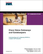
You can use a series of call fallback commands to configure PSTN fallback on the outgoing gateway. Some of the most frequently used commands are described in Table 11-4. For a complete list of the call fallback commands, go to Cisco.com. Call fallback configuration is done at global configuration mode, so it applies to all calls. However, you can disable fallback for a specific dial peer so that calls denied by the primary dial peer do not fall back to it. The only configuration needed on the terminating gateway is the ip sla responder global command. For Cisco IOS versions prior to 12.4, use the rtr responder global command.
Table 11-4. call fallback Commands
Verify PSTN fallback configuration with the show call fallback config command. If you have enabled fallback without other adjustments, this command shows you the default values. If you have changed any of the parameters, this command allows you to verify the changes. The show call fallback cache command reveals the current cache entries. The show call fallback stats command exhibits fallback statistics, such as accepted and rejected calls. You can send a test probe and view the ICPIF values with the test call fallback probe ip-address command. Two debug commands that can be helpful are debug call fallback probe and debug call fallback details.
Advanced Voice Busyout
Like LVBO, advanced voice busyout (AVBO) is used on routers that are connected to PBXs. It can busy out voice ports or trunks, causing the connected PBX to reroute its calls. AVBO, however, can make its decisions based on measurements of network conditions as well as interface status. Call fallback must first be enabled in order for probes to be sent. AVBO configuration is done either under the voice port or voice class busyout configuration modes. The command syntax to configure AVBO using probes is busyout monitor probe ip-address [codec codec-type] [icpif number | loss percent delay milliseconds].
Specifying the codec is optional, and the CAC decision can be made on either ICPIF results or packet loss and delay. The default codec is G711alaw. The default threshold is the one that the call fallback command uses. You must configure the terminating gateway as an IP SLA or RTR responder.
If you have multiple dial peers, you can use the same command in a voice class. If you are using the voice class busyout configuration, you can also trigger ABVO based on interface status with the busyout monitor interface command. You must then assign the voice class to a voice port with the voice class busyout tag command.
Resource-Based CAC Mechanisms
Resource-based CAC mechanisms examine the resources that are available for a call. These can be resources that are local to the router, such as CPU and memory, or they can be network resources, such as bandwidth. Two types of resource-based CAC—resource availability indication (RAI) and gatekeeper zone bandwidth—are used in H.323 networks with gatekeepers.
Local Gateway Resources
You can configure CAC based on local system resources when using H.323 and SIP gateways. The global call threshold command has options for global resources, such as CPU, memory, and total calls, and interface resources based on number of calls. You configure a high and low threshold. Call threshold is used in conjunction with the call treatment command, as shown in the following steps:
Step 1. Configure high and low thresholds for the appropriate router resources with the call threshold command.
Step 2. Enable treatment with call treatment on.
Step 3. Configure the type of treatment with the call treatment command.
Treatment can include hairpinning the call to a POTS dial peer, playing a message to the caller, busying out the voice interfaces, or rejecting the call and sending a cause code. When the high threshold is reached, the specified treatment is enabled. This continues until the low threshold is reached.
Additionally, you can limit the number of PSTN calls that the router receives within a configurable time with the call spike global command.
To verify your configuration, use the following commands:
• show call threshold {config | stats | status}
• show call treatment {config | stats}
• show call spike status
Gatekeeper Zone Bandwidth
In this chapter you have learned some ways that gateways can control the number of calls they allow outside their local network. In a CallManager network, CallManager can also control call admission. However, in a network that has multiple CallManager clusters or multiple gateways, it can help to have a central authority. One device (or group of devices) that tracks the available bandwidth for every cluster and location could make intelligent, dynamic call admission decisions. In an H.323 network, you can configure gatekeepers to perform that function. When using a gatekeeper, you divide your network into zones and then tell the gatekeeper the bandwidth allowed for calls within and between zones. Gateways are configured to contact the gatekeeper before allowing a call to be set up. The gatekeeper tracks the number of calls for each zone and does not allow calls that exceed the maximum bandwidth.
On the gateways, under the VoIP dial peer, configure the command session target ras. That command tells the gateway to send a Registration, Admission, and Status (RAS) message to the gatekeeper before continuing the call setup for that dial peer. You can configure a backup to the gatekeeper by using preference values with your dial peers. Set the primary dial peer with a session target of RAS so that in normal circumstances, the gatekeeper can make CAC decisions. Use preference to set a secondary dial peer pointing to the PSTN or some other local link.
For more detailed information on this topic, see Chapter 16, “Deploying Gatekeepers.”
Resource Availability Indication
Resource Availability Indication (RAI) also involves RAS messages between an H.323 gateway and gatekeeper, but in this case, it is the gateway that makes the CAC decision. The gateway sends a RAS message to its gatekeeper indicating whether it is able to accept incoming calls. RAI is useful in networks in which the gateway connects to a PBX or the PSTN via PRI circuits and processes incoming called numbers that would need to be routed out that PBX or PSTN link. RAI uses a high and a low threshold value based on the digital signal processor (DSP) and DS0 use within the gateway. When resource usage reaches the high threshold, the gateway sends an “AlmostOutOfResources” message to the gatekeeper. The gatekeeper stops sending calls for those phone numbers to that gateway. When usage falls below the low threshold value, the gateway notifies its gatekeeper, and calls are routed to that gateway once again.
For more detailed information on this topic, see Chapter 16.
Resource Reservation Protocol
RSVP is also a resource-based CAC mechanism. It is an Internet Engineering Task Force (IETF) protocol that is unique among CAC mechanisms in that it can reserve end-to-end resources for the length of the call. Other mechanisms might measure network resources at the time the call is initiated, but they cannot guarantee that conditions will remain acceptable during the call. When using RSVP, each RSVP-enabled router along the call path reserves bandwidth and the requested QoS for the duration of that call. Reservations are made on a flow-by-flow basis, so each call has its own reservation. If any router along the path cannot reserve the requested resources, the originating gateway or CallManager can reroute the call or send it as unreserved traffic.
RSVP is typically used in networks that have limited bandwidth and frequent congestion. It is most appropriate for traffic that cannot tolerate much delay or packet loss, such as voice and video, although it can be used for data, too. One drawback to RSVP is that the reservation process causes some delay in call setup. To minimize this, include RSVP control messages in your QoS configuration to ensure bandwidth and prioritized handling for them.
Some applications and devices are RSVP aware, and initiate their own reservations. More typically, either the gateways or CallManager controls the reservation process, acting in proxy for the devices to create a reserved path.
Although RSVP acts independently of the call signaling protocol, the traditional way to use it for CAC requires configuration of VoIP dial peers. Thus, traditional gateway-controlled RSVP can be used only with H.323 and SIP gateways, which require dial peers. H.323 and SIP gateways must know to delay call setup until reservations have been made; extensions to those protocols have been created to allow this. Network routers should be running at least Cisco IOS 12.1(5)T to implement gateway-controlled RSVP for H.323 traffic and 12.2(8)T for SIP. RSVP operates with both IPv4 and IPv6.
In CallManager 5.0, Cisco introduced an RSVP agent that allows RSVP to be used with all gateway protocols, including Media Gateway Control Protocol (MGCP). With RSVP agent, CallManager initiates the reservations. When a call needs a reservation to be created, CallManager instructs the RSVP agent on the gateway to begin the reservation process. The gateway reports back to the CallManager on the success or failure of the reservation, and CallManager then allows or disallows the call. This process is described in the section “CallManager-Controlled RSVP with RSVP Agent.” RSVP agent requires CallManager version 5.0 or above. It is supported in router Cisco IOS version 12.4(6)T or above on Cisco 2600XM, 2691, 2800, 3700, and 3800 routers.
Gateway-Controlled RSVP
Figure 11-2 shows how a reservation is created between two gateways when using traditional gateway-controlled RSVP. Keep in mind that this process happens in both directions. Reservations are made per flow; a flow is identified in RSVP by a destination IP address, protocol ID, and destination port. One reservation is made from terminating to originating gateway, and another reservation is made from originating to terminating gateway.
Figure 11-2. RSVP Reservation Process
In Figure 11-2, both endpoints are IP phones that are not RSVP aware.
The RSVP portion of call setup proceeds as follows:
1. A phone behind GW4 initiates an H.323 call to a phone behind GW1. When the terminating gateway, GW1, receives the call setup information, it sends an RSVP PATH message toward the IP address of the originating gateway. It does this before it tells the phone to ring. PATH messages contain the IP address of the previous hop (PHOP) so that return messages can follow the same path back. They also describe the bandwidth and QoS needs of the call traffic.
2. The next hop router, GW2, is configured with RSVP. It records the previous hop information and forwards the PATH message. Notice that it inserts its IP address as the PHOP address. The destination address is still the remote gateway.
3. The third router, GW3, does not have RSVP configured. The PATH message looks just like a normal IP packet to this router, and it routes the message untouched toward the destination, just as it does any IP packet.
4. The fourth router, GW4, is the originating gateway. When it receives the PATH, it sends an RESV message to the previous hop address listed in the PATH message. This RESV message requests the needed QoS. If any router along the way does not have sufficient resources, it returns an error message and discards the RESV message. GW4 also initiates a PATH message toward GW1 to reserve resources in the other direction.
5. The RESV and PATH messages again look like normal IP packets to GW3, the non-RSVP router, so it simply routes the packets toward GW2. No resources are reserved on this gateway.
6. GW2 receives the RESV message and checks to see if it can supply the requested resources. If the check succeeds, it creates a reservation for that flow and then forwards the RESV message to the previous hop IP address listed in the PATH message it received earlier. When the other PATH message arrives, GW2 processes it and sends it to GW1.
7. When GW1 receives the RESV message, it knows that its reservation has succeeded. However, the reservation must succeed in each direction before it can continue call setup.
GW1 responds to the second PATH message with an RESV message, which proceeds through the network as before. When GW4 receives the RESV message, resources have been reserved in both directions. GW4 responds with a ResvConf message, confirming the reservation.
8. Call setup has been delayed during the exchange of messages. When GW1 receives the ResvConf message, it knows that reservations have been made in both directions. Call setup can now proceed. RSVP then sends periodic refresh messages along the call path, enabling it to dynamically adjust to routing changes.
Configuring Gateway-Controlled RSVP
Before you configure RSVP, you need to decide how much bandwidth to allocate per flow and how much total bandwidth to allow RSVP to use, per interface. By default, you can reserve up to 75 percent of the interface bandwidth. Consider how much bandwidth is used per flow. This amount depends on the codec. By default, any flow can use up to the total reserved bandwidth, but this is configurable. Consider the expected call volume through that interface to determine the total amount of bandwidth to reserve. Remember to allow bandwidth for any other applications that use that interface.
You must configure RSVP on each router that will create reservations. It is enabled at the interface configuration mode with the ip rsvp bandwidth [total-kbps] [single-flow-kbps] command. If you do not specify the total bandwidth to reserve, the router reserves 75 percent of the interface bandwidth. If no flow value is specified, any flow can reserve the entire bandwidth.
To set the DSCP value for RSVP control messages, use the ip rsvp signalling dscp {dscp-value} interface command.
Synchronization between RSVP and call setup is enabled by default. If it has been disabled, the command to enable it is call rsvp-sync.
For RSVP to act as a CAC mechanism, also configure the requested and acceptable QoS parameters under any dial peers that RSVP will use. The req-qos command instructs the gateway to initiate an RSVP reservation for a call to that dial peer and specifies the type of QoS to request. The acc-qos command determines how strict the CAC must be. This must be done on both the originating and terminating gateways. It is recommended that both the requested and acceptable QoS be set to guaranteed-delay. The guaranteed-delay option tells RSVP to reserve bandwidth and to guarantee a minimum bit rate and priority treatment. The commands, under dial-peer configuration mode, are req-qos guaranteed-delay and acc-qos guaranteed-delay.
Example 11-9 shows a basic RSVP configuration. RSVP is enabled, and its signaling is marked with DSCP 31 under the interface configuration mode. The guaranteed delay commands are given under the outgoing dial peer.
Example 11-9. Configuring Basic RSVP
!Configure RSVP on the outgoing interface
Shanghai-GW(config)#int s2/0
Shanghai-GW(config-if)#bandwidth 1544
Shanghai-GW(config-if)#ip rsvp bandwidth 400 40
Shanghai-GW(config-if)#ip rsvp signalling dscp 31
!
!Configure QoS on the outgoing dial peer
Shanghai-GW(config-if)#dial-peer voice 3400 voip
Shanghai-GW(config-dial-peer)#req-qos guaranteed-delay
Shanghai-GW(config-dial-peer)#acc-qos guaranteed-delay
A useful command to verify your RSVP configuration is show ip rsvp interface [detail]. Example 11-10 shows the output from this command, based on the configuration in Example 11-9. After RSVP is working within your network, you can observe the reservations made with the show ip rsvp installed detail command.
Example 11-10. Verifying RSVP Configuration
Shanghai-GW#show ip rsvp interface detail
Se0/0:
Bandwidth:
Curr allocated: 0 bits/sec
Max. allowed (total): 400K bits/sec
Max. allowed (per flow): 40K bits/sec
Max. allowed for LSP tunnels using sub-pools: 0 bits/sec
Set aside by policy (total): 0 bits/sec
Admission Control:
Header Compression methods supported:
rtp (36 bytes-saved), udp (20 bytes-saved)
Traffic Control:
RSVP Data Packet Classification is OFF
RSVP resource provider is: none
Signalling:
DSCP value used in RSVP msgs: 0x1F
Number of refresh intervals to enforce blockade state: 4
Number of missed refresh messages: 4
Refresh interval: 30
Authentication: disabled
CallManager-Controlled RSVP with RSVP Agent
Cisco CallManager can use the RSVP agent feature on its gateways to provide CAC and reserve resources for calls. Resource reservation policies are configured on CallManager, and the RSVP agent on the gateway carries out these policies. The agent is a transcoding or media termination point (MTP) resource that is configured on the gateway and registered with CallManager as RSVP capable. It communicates with CallManager using Skinny Client Control Protocol (SCCP), which you must enable on the gateway.
RSVP agent provides some additional functionality over traditional gateway-controlled RSVP, including the following:
• Multilevel precedence and preemption (MLPP)—With MLPP, high-priority calls can preempt low-priority calls if bandwidth is unavailable.
• Application ID—You can create separate bandwidth pools within the total bandwidth that is allocated to RSVP. Then you can allocate traffic to those pools by application, based on an application ID. You can give video and voice traffic different application IDs and assign them to different bandwidth pools. This prevents video from using all the reservable bandwidth.
• Multiprotocol support—Because CallManager is controlling the reservation policies, no additional configuration of dial peers is needed. Thus, MGCP gateways are supported in addition to SIP and H.323.
• Interoperability with location-based CAC—You can enable RSVP use on CallManager by location, thus allowing its use for some locations but not others.
• Site awareness—If multiple calls are made to the same site, only one RSVP connection is made to that site.
Cisco RSVP agent is useful only for intracluster calls, because the same CallManager cluster must be able to control the RSVP agent on the gateway at each end of the call. You can use a Cisco IP-to-IP gateway to reserve bandwidth for intercluster calls. You cannot use the RSVP agent with device mobility, and it is not supported in Cisco CallManager Express (CME). See Cisco.com for a current list of RSVP agent capabilities.
The same router can be both an RSVP agent and a media gateway. Some overhead is involved with RSVP, however, and in a busy network you might want to use dedicated RSVP agent routers.
Note
Because RSVP reservations are made before media negotiation is done, Cisco CallManager assumes a worst-case per-flow bandwidth and asks for more bandwidth than might actually be needed. This is to prevent a post-ring failure caused by adjusting the bandwidth upward. The amount is adjusted down after media negotiation is complete. In a CallManager network, allow 96 Kbps for G.711 calls and 40 Kbps for G.729 calls when planning bandwidth.
Call flow with RSVP agents adds the SCCP communication between CallManager and the gateway. Router-to-router communication is still the same as in the traditional RSVP call flow, and reservations can be made on each router in the path. Figure 11-3 illustrates protocols that you might use in a CallManager network with RSVP agent. Both the SCCP phone and the RSVP agents on the gateways exchange SCCP messages with CallManager. The SIP phone exchanges SIP messages with CallManager. Each gateway also communicates with CallManager using its call control protocol—MGCP and SIP in Figure 11-3. The two gateways establish RSVP reservations across the IP WAN using the process shown in Figure 11-2. After the call is established, the two phones use RTP for the call media.
Figure 11-3. Using RSVP Agent with Cisco CallManager

Configuring RSVP Agent
Configuration is needed both on the gateway and CallManager. This section describes the gateway configuration. Example 11-11 shows a gateway configuration for RSVP agent. Perform the following steps to configure a gateway to use RSVP agent:
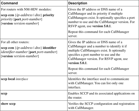
Step 1. Enable SCCP—CallManager uses SCCP to communicate with the RSVP agent on the gateway, so you must enable it on the router and bind it to the interface used to reach CallManager. You must also specify the IP addresses or DNS names of the CallManagers. Table 11-5 shows these commands.
Table 11-5. Enabling SCCP for RSVP Agent
Step 2. Configure DSP resource pooling—Enable DSP farm services on any voice cards with DSP resources that you will use for transcoding or MTPs. Under voice card configuration mode, use the dspfarm command.
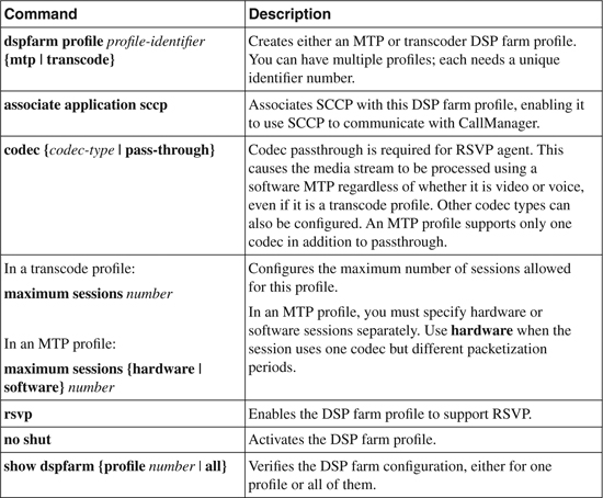
Step 3. Configure transcoding or MTP resources—You must configure transcoding or MTP resources on the gateway. This involves creating a DSP farm profile and associating the SCCP application with it. A transcode profile is needed when more than one codec is used. An MTP profile is configured for calls that use the same codec end to end. Table 11-6 shows these commands.
Table 11-6. Enabling Transcoding and MTP for RSVP Agent
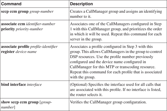
Step 4. Associate the DSP farm profiles with a CallManager group—Create a CallManager group, assign CallManager servers to it, and associate DSP farm profiles with the group. Table 11-7 shows these commands.
Table 11-7. Associating a DSP Farm Profile with a CallManager Group
Step 5. Enable RSVP on interfaces—Enable RSVP on all the gateway interfaces that will participate in making reservations. Unlike gateway-controlled RSVP, the reservable bandwidth does not need to be specified, because CallManager controls it. Use the ip rsvp bandwidth interface command.
Step 6. Enable call preemption if desired—Enable this if you would like higher-priority calls to be able to preempt lower-priority calls when all the available bandwidth is reserved. Use the ip rsvp policy preempt global command.
The previous commands are demonstrated in Example 11-11, which shows a gateway that is configured for RSVP agent. The gateway has a primary and a backup CallManager in addition to MTP and transcode DSP farm profiles, and it is using interface Gi0/0 to communicate with CallManager.
Example 11-11. Configuring a Gateway for RSVP Agent
!Configure SCCP
VG3(config)#sccp ccm 10.6.2.1 identifier 1 version 5.0.1
VG3(config)#sccp ccm 10.6.2.2 identifier 2 version 5.0.1
VG3(config)#sccp local gi0/0
VG3(config)#sccp
!
!Configure the voice card for DSP farm
VG3(config)#voice-card 1
VG3(config-voicecard)#dspfarm
!
!Configure DSP farms
VG3(config)#dspfarm profile 1 mtp
VG3(config-dspfarm-profile)#associate application sccp
VG3(config-dspfarm-profile)#codec pass-through
VG3(config-dspfarm-profile)#maximum sessions software 10
VG3(config-dspfarm-profile)#rsvp
VG3(config-dspfarm-profile)#no shut
!
VG3(config)#dspfarm profile 2 transcode
VG3(config-dspfarm-profile)#associate application sccp
VG3(config-dspfarm-profile)#codec g711ulaw
VG3(config-dspfarm-profile)#codec g729ar8
VG3(config-dspfarm-profile)#codec pass-through
VG3(config-dspfarm-profile)#maximum sessions 5
VG3(config-dspfarm-profile)#rsvp
VG3(config-dspfarm-profile)#no shut
!
!Create a CallManager group and associate the profiles with it
VG3(config)#sccp ccm group 1
VG3(config-sccp-ccm)#bind interface gi0/0
VG3(config-sccp-ccm)#associate ccm 1 priority 1
VG3(config-sccp-ccm)#associate ccm 2 priority 2
VG3(config-sccp-ccm)#associate profile 1 register mtp_1
VG3(config-sccp-ccm)#associate profile 2 register xcoder_1
!
!Enable RSVP on each interface that will create reservations
VG3(config)#interface gi0/0
VG3(config-if)#ip rsvp bandwidth
!
!Enable call preemption
VG3(config)#ip rsvp policy preempt
You must also configure the CallManager Publisher to use RSVP. Configure RSVP policies for locations or for the cluster as a whole. To use RSVP, the two call endpoints must belong to different locations. Create media resource groups, and add any transcoders or MTPs that will be registered as an RSVP agent. Then configure a media resource group list (MRGL) and assign a media resource group to the list. Assign the MRGL to a device pool. See Cisco.com for complete information on configuring Cisco CallManager for RSVP agent.
RSVP and the IntServ/DiffServ Model
RSVP reserves resources, but it is up to each router to implement the appropriate QoS techniques to deliver those resources. Low-latency queuing (LLQ) is the QoS mechanism typically used for voice, putting voice in a priority queue with guaranteed but policed bandwidth. This is part of the DiffServ model of QoS. However, RSVP has its own set of queues that it puts reserved traffic into by default. These queues have a low weight, but they are not prioritized. This is part of the IntServ model of QoS. What is needed is a way to put reserved voice traffic into the LLQ—the IntServ/DiffServ model.
By default, RSVP uses weighted fair queuing (WFQ) to provide its QoS. When using LLQ with class-based weighted fair queuing (CBWFQ), disable the RSVP use of WFQ with the ip rsvp resource-provider none interface command. Also, by default, RSVP attempts to process every packet—not just provide CAC. Turn this off with the ip rsvp data-packet classification none interface command. Then you can configure the LLQ and CBWFQ as usual. RSVP reserves bandwidth for voice calls, and the QoS processes of the gateway place that voice traffic into the priority queue. In Example 11-10, note under the Traffic Control section that these two commands have been given.
When you are using LLQ, the priority queue size includes Layer 2 overhead. The RSVP bandwidth statement does not take Layer 2 overhead into consideration. Therefore, when you are using both LLQ and RSVP, set the RSVP bandwidth equal to the priority queue minus the Layer 2 overhead. You can find instructions for configuring LLQ, CBWFQ, and RSVP on Cisco.com in the “Quality of Service Solutions Configuration Guide” and in Cisco IOS Command Reference Guides. See the case study at the end of this chapter for an example of using RSVP with LLQ.
Incorporating RSVP into the Voice Network
It is not necessary to configure RSVP on every router within your enterprise. Because RSVP messages are passed through non-RSVP-enabled routers, you can use RSVP selectively. You might enable it in sections of the network that are prone to congestion, such as areas with low bandwidth. In the core of the network, where bandwidth is higher, you might rely on LLQ/CBWFQ to handle voice and video traffic. This helps in scaling RSVP, cutting down on the number of routers that must track each session and be involved in RSVP messaging.
Figure 11-4 shows a network with remote sites connecting to a core IP WAN. The core might be enterprise owned, or it might, for example, be a Multiprotocol Label Switching (MPLS) network of the service provider. All the remote site links are T1 and carry both voice and data. All WAN interfaces of the remote site routers are configured for RSVP. Bandwidth is reserved when sites place calls between each other. When these calls go across the core IP WAN, reservations are made on the WAN interfaces of the edge routers, and CAC is done based on resources that are available on the remote site routers. The core does not participate in RSVP, so you must use other means of QoS in that part of the network.
Figure 11-4. Using RSVP in a Large Network

POTS-to-POTS Call Routing Considerations
Occasionally, you must route calls between POTS dial peers. CAC might cause this, such as when a call from a PBX is denied admission to the WAN and sent back to the PBX. Or a call from an analog phone might be routed over the PSTN. The ability to switch calls between POTS dial peers is enabled by default on Cisco gateways.
Many of the CAC mechanisms that are described in this chapter use hairpinning, or tromboning, in which a call both enters and exits on the same interface. Suppose that a router doing toll bypass receives an analog call from its PBX. This call is matched to an incoming POTS dial peer. Typically the analog call is terminated, regenerated as a VoIP call, and then routed out a VoIP dial peer. However, the CAC configuration of the gateway might cause the call to be rejected for sending over the IP network. When a call is rejected, you can redirect (or hairpin) it back to the PBX. Both legs of the call thus traverse the same router interface. The PBX then looks for an alternate route, such as out to the PSTN.
A hairpinned POTS call is terminated on the gateway and then routed out another POTS dial peer as a new call leg. When this happens, DSPs are assigned to the incoming leg of the POTS call and also to the outgoing (hairpinned) leg. These DSP resources stay assigned for the duration of the call; thus, each hairpinned call doubles the DSP usage.
Routing between ISDN POTS dial peers can use TDM switching, but this must be done across a bus that supports it. With TDM switching, DSP resources are assigned when the call is received, but media DSPs are dropped after the call is switched to another POTS port. No DSP is needed for the media because an internal TDM connection is made between the incoming and outgoing ports on the TDM bus. This is an advantage with nonvoice calls, such as modem, fax, and video.
Older routers, such as the 1700, 2600, 3600, and 3700 series, support TDM switching only between ports on certain network modules. Both legs of the call must stay on the same module. Cisco Integrated Services Routers (ISR) support TDM switching across the backplane; thus, POTS-to-POTS calls can be routed between different network modules. Other Cisco gateways, such as the Access Server (AS) and Integrated Access Device (IAD) lines, also support TDM switching across their backplane, and thus, can route POTS calls between interfaces. These are typically used in a service provider environment.
Modules that support intramodule TDM switching include these:
• NM-HDV
• NM-HDV2
• NM-HDV2-1T1/E1
• NM-HDV2-2T1/E1
• NM-HD-1V/2V/2VE
• EVM-HD-8FXS/DID
• AIM-VOICE-30
• VWIC
ISRs allow intermodule TDM call routing between the following modules:
• VWIC
• NM-HDV2
• NM-HD-1V/2V/2VE
• EVM-HD-8FXS/DID
You must synchronize clocking when you are switching between these ports and modules. Chapter 7, “Connecting to PBXs,” describes how to do this.
Case Study: Implementing Gateway-Controlled RSVP
The link between the New York and the Leeds office tends to be fairly congested, so the decision is made to implement RSVP between the two gateways. In addition, LLQ and CVWFQ are applied to the IP WAN interface. RSVP signaling is marked with DSCP 31 and is given a share of the interface bandwidth.
Example 11-12 shows the configuration of the New York gateway to implement RSVP and add the desired queueing. Only the New York router configuration is shown, but you must configure the Leeds router similarly. Use the same required and acceptable QoS dial peer configuration on both gateways. The LLQ and CBWFQ configuration should be the same on both routers, also.
Example 11-12. Case Study: Configuring RSVP and LLQ for Voice
!Identifies RTP traffic
NY-GW1(config)#ip access-list extended RTP
NY-GW1(config-ext-nacl)#permit udp any any range 16383 32767
NY-GW1(config-ext-nacl)#permit udp any range 16383 32767 any
!
!Identifies H.323 signaling traffic
NY-GW1(config-ext-nacl)#ip access-list extended H323
NY-GW1(config-ext-nacl)#permit tcp any eq 1720 any
NY-GW1(config-ext-nacl)#permit tcp any any eq 1720
!
!
!Creates a class for voice media matching ACL RTP
NY-GW1(config-ext-nacl)#class-map match-all VOIP-Media
NY-GW1(config-cmap)#match access-group name RTP
!
!Creates a class for voice signaling matching ACL H323
NY-GW1(config-cmap)#class-map match-all VOIP-Signal
NY-GW1(config-cmap)#match access-group name H323
!
!Creates a class for RSVP signaling matching DSCP configured on interface S0/0
NY-GW1(config)#class-map RSVP-Signal
NY-GW1(config-cmap)#match dscp 31
!
!Creates a policy for LLQ and CBWFQ
NY-GW1(config-cmap)#policy-map RSVP
NY-GW1(config-pmap)#class VOIP-Media
NY-GW1(config-pmap-c)#priority percent 30
NY-GW1(config-pmap-c)#class VOIP-Signal
NY-GW1(config-pmap-c)#bandwidth percent 5
NY-GW1(config-pmap-c)#class RSVP-Signal
NY-GW1(config-pmap-c)#bandwidth percent 5
NY-GW1(config-pmap-c)#class class-default
NY-GW1(config-pmap-c)#fair-queue
NY-GW1(config-pmap-c)#random-detect
!
!Configures the interface for RSVP and applies the policy
NY-GW1(config-pmap-c)#int s0/0
NY-GW1(config-if)#ip rsvp bandwidth 400 40
NY-GW1(config-if)#ip rsvp resource-provider none
NY-GW1(config-if)#ip rsvp data-packet classification none
NY-GW1(config-if)#ip rsvp signalling dscp 31
NY-GW1(config-if)#service-policy output RSVP
!
!Configures the dial peer to Leeds for RSVP
NY-GW1(config-if)#dial-peer voice 50300 voip
NY-GW1(config-dial-peer)#destination-pattern 50[34]..
NY-GW1(config-dial-peer)#session target ipv4:10.40.25.1
NY-GW1(config-dial-peer)#req-qos guaranteed-delay
NY-GW1(config-dial-peer)#acc-qos guaranteed-delay
NY-GW1(config-dial-peer)#forward-digits 4
Review Questions
1 Name three types of CAC.
2 What CAC mechanism would you use to guarantee enough bandwidth for the duration of a call?
3 How are dial peers configured to be part of the same hunt group?
4 What is the difference between LVBO and AVBO?
5 Which CAC mechanism, other than AVBO, uses probes in making its call admission decision?
6 What is TEHO used for, and what are two issues with its use?
7 What are some differences between gateway-controlled RSVP and CallManager-controlled RSVP?
8 Given the following dial peers, which would the gateway use first? Second? Third?
dial-peer voice 2200 voip
preference 1
destination-pattern 2200
session target ipv4:10.20.25.1
dial-peer voice 2201 voip
destination-pattern 2200
session target ipv4:10.20.26.2
dial-peer voice 2202 voip
preference 4
destination-pattern 2200