Chapter 3. H.323
H.323 is a standard for communication protocols from the International Telecommunications Union Telecommunication Standardization Sector (ITU-T); Version 4 is the current version. H.323 was created to provide multimedia communication across a packet network. The protocol can handle video and data, in addition to audio. H.323 interoperates well with the public switched telephone network (PSTN) in translating between call setup and control signals used in an IP network and those used in a switched-circuit network. H.323 is widely used in video conferencing deployments.
Gateways that use H.323 do not depend on a call agent, as with Media Gateway Control Protocol (MGCP). H.323 is the default gateway protocol on Cisco routers. This chapter focuses on Cisco IOS H.323 gateways, although the concepts apply to all H.323 gateways.
In this chapter you will learn
• Call flow with H.323 gateways
• H.323 protocol pros and cons
H.323 Specifications
The H.323 standard is actually a suite of specifications that controls voice and video transmission over IP networks. The following are some commonly used specifications:
• H.225—Handles call setup and teardown between H.323 devices on a packet-based network, terminal to gatekeeper signaling using Registration, Admission, and Status Protocol (RAS), and call signaling. H.323 can use ISDN Q.931 signals, formatted as H.225 messages, to interoperate with legacy voice networks.
• H.235—Specifies security for messages between the gateway and gatekeeper.
• H.245—Controls the traffic flow, performs DTMF Relay, limits media transmission rates, negotiates capability, and controls opening and closing channels for media streams. Uses TCP.
• H.261 and H.263—Specify video conferencing standards.
• H.450—Controls supplementary services between H.323 entities. Examples of supplementary services include call waiting, hold, transfer, park, and pickup.
• T.120—Used for real-time multipoint data transfer during videoconferences. Allows application sharing, whiteboarding, and file transfer. Uses TCP.
• H.320—Defines the standard for video conferencing over ISDN networks. H.320 uses H.221 frames for media. It requires a gateway to interwork with H.323 conferencing over IP because H.221 frames must be translated into RTP packets, and vice versa.
H.323 Network Components
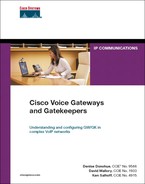
H.323 has several functional components, which you can implement separately on different devices, or as multiple functions on the same device. The basic components include gateways, gatekeepers, terminals, and multipoint control units (MCU). You can also use proxy servers. Figure 3-1 illustrates these components. A Cisco CallManager is also shown. It is not part of the H.323 specification, but it can interact with H.323 devices.
Figure 3-1. H.323 Network Components
H.323 Gateways
H.323 gateways translate between different types of networks, just as any gateway does. In Figure 3-1, the gateways use H.323 to communicate with each other, the gatekeeper, CallManager, and the other H.323 devices in the network. H.323 gateways can register with a gatekeeper. They can also register analog phones in their network with the gatekeeper. H.323 gateways have the intelligence to place and receive calls, although CallManager can also control calls. Dial peers are configured on the gateway, with destination patterns. A Voice over IP (VoIP) dial peer points to the CallManager for each range of internal phone numbers it controls. CallManager sends outgoing PSTN calls to the gateway, which uses plain old telephone service (POTS) dial peers with the appropriate destination patterns to route them.
H.323 Gatekeepers
Gatekeepers provide a centralized point to resolve E.164 phone numbers to IP addresses and do call admission control. They can provide call routing and control, security, and bandwidth management, and they can simplify dial peer configuration. In Figure 3-1, when a call needs to go to an IP phone in the other network, the gateway must contact the gatekeeper before the call can proceed.
When people make calls between IP phones that the same CallManager cluster controls, the CallManager maps the called phone number to a destination IP address. When they make calls between clusters, they can optionally use an H.323 gatekeeper to route the call to the appropriate gateway or CallManager. Both CallManager and H.323 gateways can use the services of a gatekeeper. The originating gateway (or CallManager) sends a request to the gatekeeper to admit the call, and the gatekeeper responds with the IP address of the terminating gateway or CallManager. Call setup and voice media can then be sent directly between the originating and terminating peers.
H.323 Terminals
Like MGCP, H.323 uses the concept of endpoints. IP phones and video conferencing stations, in addition to gateways and CallManagers, can be H.323 endpoints. An H.323 terminal is an endpoint that is able to do real-time two-way communication. All H.323 terminals must support H.225 for call setup, H.245 for channel and capability control, RAS for communicating with a gatekeeper, and Real-Time Transport Protocol (RTP)/Real-Time Transport Control Protocol (RTCP) for media streams. They can optionally support the other H.323 specifications. The most common type of H.323 terminal is a video conferencing system.
Multipoint Control Units
An MCU allows multiple participants in a conference. In Figure 3-1, if the three H.323 video systems want to participate in a conference, the MCU controls that. An MCU is composed of a multipoint controller (MC) and a multipoint processor (MP). The MC handles the H.245 capabilities negotiation and controls the conference resources. The MP does the actual mixing and splitting of the audio and video streams, and translation between different codecs or bandwidth.
H.323 Proxy Servers
H.323 proxy servers do the call setup and teardown in place of the endpoint. They can provide security, quality of service (QoS), and application-specific routing (ASR). In Figure 3-1, a Cisco router is configured as an H.323 proxy server. It can communicate with the gatekeeper and endpoints in the other network, thus hiding their real IP address of endpoints in its network. Two proxy servers can implement Resource Reservation Protocol (RSVP) for calls between them, in proxy for their non-RSVP aware endpoints. With ASR, a proxy server routes traffic based on the application used, rather than the IP address. For instance, voice traffic could be directed to a special QoS-enabled path, instead of taking the same path as data.
Call Flow
Each protocol that is used in the call flow creates a logical channel for its traffic. Each channel is one-way, so you must open two channels in each direction for each protocol. If the call includes a T.120 data transfer, such as application sharing, T.120 creates and controls its own data channels. Basic H.323 call flow involves the following steps:
Step 1. The H.323 gateways exchange H.225 call setup messages, using TCP port 1720. One of those, the Connect message, contains the control channel address to use for H.245 signals.
Step 2. The gateways exchange several H.245 capabilities negotiation messages. When the negotiation is successful, the gateways exchange the calling endpoint IP address and RTP port numbers, and the called endpoint IP address with RTP port numbers, in OpenLogicalChannel messages.
Step 3. The call is successful, and RTP media streams are sent.
H.323 Fast Start
Recent versions of H.323 implement H.323 Fast Start. You might also see this called Fast Connect. In a sense, this tunnels H.245 traffic inside H.225 messages. When you are using H.323 Fast Start, one of the setup messages includes a FastStart element, which contains a list of capabilities and supported coder/decoder (codec) options for both sending and receiving. The other gateway responds by including a FastStart element in one of its messages, listing the capabilities and codec it has selected. After the first gateway receives this, it can begin media transmission right away, without having to open separate H.245 channels. If it needs to send other H.245 messages after the media stream has begun, it can tunnel those messages over the H.225 channel.
Figure 3-2 gives you an overview of the various protocols and signals used in an H.323 call using Fast Start. Some information has been simplified for the sake of space.
Figure 3-2. H.323 Call Flow with Fast Start
In Figure 3-2, an IP phone is making a call to a non-IP phone. The IP phone communicates with its CallManager using Skinny Client Control Protocol (SCCP). The CallManager exchanges H.323 messages with the H.323 voice gateway using Fast Start. The gateway is connected to the PSTN by a PRI line, and it uses ISDN signaling over that connection. Notice that the H.323 gateway terminates both the Q.921 and the Q.931 signaling, which is different from MGCP operation. The infrastructure on the other end (not shown) communicates with the analog phone.
The first four H.323 messages are H.225 call signaling—setup, call proceeding, alerting, and connect. Contained within these messages is the H.245 information. If all these signals succeed, the call is active. A separate unidirectional RTP channel between the IP phone and the gateway is then opened in each direction. A bidirectional RTCP channel is also opened. The gateway translates between the RTP and time-division multiplexing (TDM) networks, and it establishes a TDM media stream between it and the analog phone. When the analog phone hangs up, the gateway receives a Q.931 disconnect and translates that to an H.245 EndSession message. You do not have to configure Fast Start—it is used by default unless any of the following conditions is present:
• One of the gateways either does not support or rejects the use of Fast Start. The gateway signals this by the absence of a FastStart element in any of the setup signals, up to and including the Connect message.
• The called gateway selects different codecs for sending and receiving.
• Recent versions of the Cisco IOS use Fast Start for calls that RSVP initiates. You might have to enable slow start for backward compatibility with older versions.
When any of these occur, separate H.245 channels are opened, and the sending and receiving capabilities are negotiated the slow way.
H.323 Protocol Pros and Cons
The H.323 protocol has some benefits and some drawbacks.
Pros
The following are some H.323 protocol benefits:
• Caller ID—H.323 provides caller ID from Foreign Exchange Office (FXO) and T1 channel-associated signaling (CAS) ports, whereas MGCP does not.
• Fractional PRI—H.323 supports the use of a fractional PRI.
• Interoperability—H.323 is widely used and interoperates well with applications and devices from multiple vendors. Because all H.323 devices must support the core protocols, a gateway and CallManager have no version dependence.
• Granular call control—H.323 allows a great amount of control over the treatment of calls to and from the gateway, such as for digit manipulation, load balancing, and call rerouting. You can use Toolkit Command Language (Tcl) and voice extensible markup language (VXML) applications.
• Legacy systems support—You can integrate legacy systems based on POTS or ISDN lines into your H.323 network. H.323 supports more types of TDM interfaces and signaling than MGCP.
• Multimedia support—You can use H.323 for both voice calls and video conferencing. H.323 also allows data transfer.
• Non-Facility Associated Signaling (NFAS) support—H.323 supports NFAS, which allows you to control multiple ISDN PRI lines with just one D channel, thus giving you more usable channels.
• H.323 gatekeepers—Gateways can point to a gatekeeper for call control and address resolution.
• PRI call preservation—Because the gateway terminates both Q.921 and Q.931 signaling, the loss of its CallManager does not require dropping calls using the PRI line.
Cons
The H.323 protocol drawbacks include the following:
• Configuration—Gateway configuration is more involved than with MGCP because of the need for dial plan information for the dial peers. H.323 gateways would need a complex configuration to achieve the same functionality as CallManager partitions and Calling Search Spaces. The use of gatekeepers can eliminate some of this complexity.
• Lack of centralized dial plan—When you make changes to the dial plan, you must reconfigure all the gateways to reflect that change. With MGCP, however, only the CallManager needs the dial plan information. Using a Gatekeeper alleviates this somewhat.
• Security—H.323 does not support the use of secure RTP in Cisco IOS versions before the later releases of 12.4T.
• Call survivability—The default configuration of H.323 does not support call survivability. By default, if the connection to the CallManager is lost, all active calls are dropped. When using Survivable Remote Site Telephony (SRST), CallManager terminates active calls when it comes back online.
• Q Signaling (QSIG) facility IE support—H.323 has no support for QSIG facility IE; therefore, information (such as calling name and redirect number) that is carried in the facility IE is lost. The integration of a QSIG PBX with Cisco IP Telephony requires the use of MGCP.
When to Use H.323
People sometimes avoid using H.323 gateways because they seem more complex to configure than MGCP. Because CallManager does not control H.323 endpoints, you must create dial peers on the gateway to reflect your call routing plan. This has some benefits, however. You have more flexibility and control over calls. For example, if you need to block incoming calls from a specific number, configuring that on an incoming H.323 dial peer stops the call at the gateway. No resources are wasted between the gateway and CallManager to deny the call. You can configure settings, such as QoS value, preference, and codecs, directly on the dial peers. Also, an MGCP gateway router uses H.323 dial peers when operating in SRST mode, so you need to configure those peers anyway.
H.323 is ideal for remote sites and branch offices so that the call control signaling does not have to traverse the WAN. Sites that have a PRI link should consider H.323 because they would not lose existing calls over that link during transition to SRST. H.323 is also preferred when using a fractional PRI, because it is more complicated to configure fractional PRI support on the CallManager than on an H.323 gateway. Caller ID for incoming calls on an FXO port is supported only with H.323. Sites that have Toolkit Control Language (Tcl) or VXML applications would need to use H.323.
You must use H.323 gateways in a network with H.323 gatekeepers. Use H.323 when you need to interoperate with other H.323 devices, such as videoconferencing systems, and when performing multimedia communication. If you are not using a CallManager, H.323 is the default voice gateway protocol on Cisco routers.
Dial Plan Considerations
In a voice network that has CallManagers and H.323 gateways, you need to understand the interaction between the two so that you can properly configure call flow. On the CallManager, you configure a dial plan to send calls to the H.323 gateways when needed. On the H.323 gateways, you configure dial peers to forward calls out of the gateway. You can forward calls to a CallManager using a VoIP dial peer, to the PSTN as a POTS dial peer, to another gateway using a VoIP dial peer, or to directly connected voice ports as POTS dial peers.
You can control the treatment of incoming and outgoing calls with dial peers. In your dial planning, consider the need for such things as number translations or other digit manipulations, or call restrictions. If you are using SRST, be sure the dial plan will work both with and without CallManager.
You need at least one dial peer with a destination pattern to route outgoing calls. Default incoming POTS and VoIP dial peers exist, but you should specifically configure dial peers for incoming calls if you need nondefault services. The default VoIP dial peer includes the following configuration:
• It uses G729r8 codec.
• Voice activity detection (VAD) is enabled.
• Dual tone multifrequency (DTMF) relay is disabled.
• Preference is 0.
• Voice media has differentiated services code point (DSCP) of expedited forwarding (EF); signaling is AF31.
• Huntstop is disabled.
• Both Req-qos and Acc-qos are best-effort.
• No Tcl applications are applied.
• Fax relay is disabled.
• Playout-delay is 40 ms.
The default POTS dial peer includes the following settings:
• Direct inward dial is disabled.
• Preference is 0.
• Digit strip is enabled.
• Register the E.164 phone number with a gatekeeper.
• Huntstop is disabled.
• No Interactive Voice Response (IVR) applications are applied.
Because you must configure an H.323 gateway with the information you need to route calls, the configuration can get complex in a large network. You can simplify the configuration by creating a hierarchical structure using gatekeepers and perhaps a directory gatekeeper.
When you use a gatekeeper, the gateway routes all inbound calls to its local network, but it communicates with the gatekeeper for outbound calls to unknown phone numbers. This simplifies the configuration because the gateway does not need to know how to reach every phone number in your network.
Implementing H.323 Gateways
Before you enable H.323, configure the router with a hostname, IP addressing, and routing information. Give careful thought and planning to the dial peer configurations and settings you will use. The following are some common settings to specify:
• Codec
• DTMF Relay method
• Dial peer preference
• VAD
• QoS DSCP values
• Call progress indicators
• Fax relay information
• Direct-inward-dial
Voice Class Configuration
You can create a voice class to apply configurations to specific dial peers or voice ports. Several types of configurations are possible. This section looks at two: codec and H.323 parameters.
A codec voice class allows you to control the codec negotiation by specifying which codecs will be offered, and a preference value for each codec. Use the voice class codec tag# command to create the voice class. Then list codecs and preferences with the codec preference priority codec-type command. The priority value range is 1 to 14, with 1 being the highest priority. Apply the voice class to a dial peer with the voice-class codec tag# command.
The voice class h323 tag# command creates a voice class that allows you to configure the items shown in Table 3-1. The exact commands available depend on your Cisco IOS version and feature set.
Table 3-1. Voice Class H323 Options

Example 3-1 shows a basic H.323 dial peer configuration. A voice class has been created to control the codecs that are negotiated and their preferred order.
Example 3-1. Configuring H.323 Dial Peers
NYCgateway(config)#voice class codec 1
NYCgateway(config-class)#codec preference 1 g729r8
NYCgateway(config-class)#codec preference 2 g729br8
NYCgateway(config-class)#codec preference 3 g711ulaw
!
NYCgateway(config)#dial-peer voice 100 voip
NYCgateway(config-dial-peer)#incoming called-number .
NYCgateway(config-dial-peer)#no vad
!
NYCgateway(config-dial-peer)#dial-peer voice 10 voip
NYCgateway(config-dial-peer)#destination-pattern 1...
NYCgateway(config-dial-peer)#session target ipv4:10.1.10.10
NYCgateway(config-dial-peer)#no vad
NYCgateway(config-dial-peer)#voice-class codec 1
!
NYCgateway(config-dial-peer)#dial-peer voice 900 pots
NYCgateway(config-dial-peer)#incoming called-number .
NYCgateway(config-dial-peer)#direct-inward-dial
!
NYCgateway(config)#dial-peer voice 9 pots
NYCgateway(config-dial-peer)#destination-pattern 9T
NYCgateway(config-dial-peer)#direct-inward-dial
NYCgateway(config-dial-peer)#preference 1
NYCgateway(config-dial-peer)#port 3/0:23
!
NYCgateway(config-dial-peer)#dial-peer voice 99 pots
NYCgateway(config-dial-peer)#destination-pattern 9T
NYCgateway(config-dial-peer)#direct-inward-dial
NYCgateway(config-dial-peer)#preference 2
NYCgateway(config-dial-peer)#port 1/0/0
In this example, a voice class and several dial peers are configured.
1 A voice class was configured to list the preferred order for codecs to be negotiated.
2 Dial peer 100 is a default dial peer for incoming VoIP traffic. The incoming called-number command tells the router to look for a match to the dialed number identification service (DNIS) number of the incoming call. In this example, the command uses the . (period) wildcard, which matches all called numbers. VAD is turned off for these calls.
3 Dial peer 10 forwards calls for IP phones to the CallManager (IP address 10.1.10.10). The IP phone number range is 1000 through 1999, matched by the destination pattern 1... using wildcards for the last three digits. VAD is turned off for these calls, DTMF Relay is specified, and the codec voice class is associated with this dial peer.
4 Dial peer 900 is a default dial peer for calls that come in from the PSTN. It matches all called numbers with the . (period) wildcard and enables direct inward dial. This tells the router not to send a secondary dial tone to the caller, but to collect all the incoming digits.
5 Dial peer 9 is the preferred peer for all calls to the PSTN. The destination pattern is 9T. This assumes that users dial a 9 for outside calls. The “T” tells the router to expect a variable length dial string and to wait for the interdigit timeout to expire before matching this dial peer. 9T matches emergency calls in addition to regular ones, but you might want to explicitly configure matches for emergency numbers to avoid waiting for the interdigit timeout. This dial peer has a preference value of 1, and it is associated with the PRI port.
6 Dial peer 99 is also a POTS dial peer, and it, too, has a destination pattern of 9T and direct inward dial configured. It has a preference value of 2, so it will be used only if dial peer 9 is unavailable (lower preference wins). This dial peer is associated with FXO port 1/0/0.
Voice Service VoIP Configuration
The voice service commands cover some of the same parameters as voice classes, but these commands apply to the gateway as a whole. An individual gateway could have both voice service configuration and voice class configuration. In that case, configuration that is applied to an individual dial peer takes precedence over global configuration.
Four configuration submodes exist: POTS, Voice over ATM (VoATM), Voice over Frame Relay (VoFR), and VoIP. This section covers some of the VoIP options. The command to enter voice service configuration mode is given at the global configuration prompt: voice service {pots | voatm | vofr | voip}.
One use of the voice service configuration is call redirection. Consider the network shown in Figure 3-3. GW1 has a PRI line and is in a CallManager route group. GW2 has a couple of POTS lines.
Figure 3-3. Allowing H.323 Call Redirection
When the IP phone needs to send a call to the PSTN, the CallManager directs it to GW1. But suppose that the PRI line is full. The call could go out over one of the POTS lines on GW2, but the CallManager will not redirect it. You can configure the router to do so, however. On GW1, create a VoIP dial peer for PSTN numbers, with a higher preference value so that it is less preferred, and a session target of GW2. On Cisco IOS Software versions later than Release 12.3(7)T, you must enable this capability with the allow-connections h323 to h323 command:
GW1(config)#voice service voip
GW1(conf-voi-serv)#allow-connections h323 to h323
The allow-connections command allows a Cisco router or CME to route between VoIP dial peers. You might use it when hairpinning or redirecting calls, as shown. Other options include the allow-connections h323 to sip command and the allow-connections sip to h323 command.
Call survivability can be an issue with H.323. By default, an H.323 gateway exchanges H.225 keepalives with CallManager. When those keepalives fail, active calls are torn down. H.323 gateways can use SRST for backup when the CallManager is unreachable. The CallManager resets all active calls when it resumes the connection to the H.323 gateway. To prevent active calls from being terminated when the CallManager becomes unreachable, turn off H.225 keepalives between the gateway and CallManager. You do this in the h323 submode of the voice service voip command, as the following code shows:
GW1(config)#voice service voip
GW1(conf-voi-serv)#h323
GW1(conf-serv-h323)#no h225 timeout keepalive
You can stop the H.323 service in this submode by giving the following commands. You can then restart it in the same mode with the no call service stop command:
GW1(config)#voice service voip
GW1(conf-voi-serv)#h323
GW1(conf-serv-h323)#call service stop
Finally, you can control Fast Start globally. (Use a Voice Class to configure it for specific dial peers.)
GW1(config)#voice service voip
GW1(conf-voi-serv)#h323
GW1(conf-serv-h323)#call start slow
Toll Bypass
Companies that have their business in different areas might find that they spend a significant amount of money on long-distance calls between those locations. One way to minimize that cost is to use VoIP for intracompany calls. With toll bypass, calls between company locations are sent over the IP network as VoIP when bandwidth is available, and they are routed over the PSTN when no bandwidth is available. Calls can be sent over the WAN using Frame Relay or ATM, or over direct connections, such as T1 links. Voice typically shares bandwidth with data in this situation. Therefore, you must give careful consideration to QoS.
If you are using a multisite CallManager network, you are already doing something similar, with CallManager controlling the routing of intracompany calls over the WAN. However, even companies that have a PBX and analog phones can use toll bypass. They can connect the PBX to a router using standard analog or digital interfaces. The router then packetizes the voice traffic and routes it over the WAN to its peer gateway. The terminating gateway receives the IP voice traffic and, if it is also connected to a PBX, sends the call through the PBX to analog phones.
Note
Call Admission Control (CAC) and QoS become critical in this type of network. For more information, see Chapter 7, “Connecting to PBXs,” Chapter 8, “Connecting to an IP WAN,” and Chapter 11, “Influencing Path Selection.”
Example 3-2 shows a voice gateway router that is configured to enable toll bypass. The Shanghai gateway router has one PRI to the PSTN (port 1/0) and another PRI to the PBX (port 2/0). It is configured to use toll bypass for its traffic to the New York office. New York also has a router that is connected to a PBX—the two routers do toll bypass between each other. Only the Shanghai configuration is shown in this example. Of course, the company needs to configure the router at the New York office similarly. This network is diagramed in Figure 3-3.
Example 3-2. Configuring Dial Peers for Toll Bypass
ShanghaiGW(config)#dial-peer voice 212 voip
ShanghaiGW(config-dial-peer)#destination-pattern 121255521..
ShanghaiGW(config-dial-peer)#session target ipv4:10.1.25.1
!
ShanghaiGW(config)#dial-peer voice 213 pots
ShanghaiGW(config-dial-peer)#destination-pattern 121255521..
ShanghaiGW(config-dial-peer)#preference 1
ShanghaiGW(config-dial-peer)#direct-inward-dial
ShanghaiGW(config-dial-peer)#forward-digits all
ShanghaiGW(config-dial-peer)#port 1/0:23
!
ShanghaiGW(config-dial-peer)#dial-peer voice 21 pots
ShanghaiGW(config-dial-peer)#destination-pattern 2155541..
ShanghaiGW(config-dial-peer)#direct-inward-dial
ShanghaiGW(config-dial-peer)#forward-digits 4
ShanghaiGW(config-dial-peer)#port 2/0:23
Dial peers 212 and 213 have the same destination pattern for a range of phone numbers at the New York office. Dial peer 212 will be preferred, because it has the default preference value of 0, and dial peer 213 has been given a preference of 1. Calls to the New York office will be routed over the WAN if possible, as a toll-free call. Those calls will go over the PSTN only if the WAN is down or if bandwidth is insufficient for the call.
The IP address in the dial peer 212 session target is the New York office router. The port that is specified in dial peer 213 is the PRI to the PSTN. Dial peer 21 forwards all traffic that is bound to the analog phones out the PRI to the PBX. The forward-digits 4 command instructs the router to send only the last four digits of the called number to the PBX.
Figure 3-4 shows the network between the New York and the Shanghai offices. Toll bypass is configured on the two routers that are connected to PBXs at each location, to enable them to send interoffice calls over the IP WAN.

Defining H.323 Gateways on CallManager
If the gateway will be part of a Cisco Unified Communications system, you need to configure it to peer with CallManager. You must still configure the dial peers and any dial peer options you need. Configure an additional VoIP dial peer for routing calls that are bound to other phones in the cluster. List the IP address of the CallManager as its session target. The destination pattern will depend on your dial plan, but you should specify intracluster calls. If your dial plan is complex, you might need several VoIP dial peers to cover it.
After you configure the gateway, configure CallManager to recognize and use it.
Step 1. The CallManager configuration for an H.323 gateway is fairly simple. In CallManager Administration, go to the Device menu and select Gateway from the drop-down list. When the Find and List Gateways page opens, select the Add a New Gateway link.
Step 2. Figure 3-5 shows the next page. Select H.323 Gateway from the drop-down list next to Gateway Type. Notice that the server automatically fills in the Device Protocol box with H.225. Click the Next button.
Figure 3-5. Adding an H.323 Gateway to CallManager

Step 3. On the next screen, shown in Figure 3-6, you enter information about the gateway.
For Device Name, enter the IP address of the router. Notice that only one IP address is allowed. If the router might use multiple interfaces to communicate with its CallManager, you need to tell the router which one to use as the source of its messages (possibly a loopback interface). Use the h323-gateway voip bind srcaddr ip-address command, under interface configuration mode.
Add a description and select the CallManager device pool to which the gateway will belong. The Location field is used to control the number of calls allowed to a site, to ensure that each call has enough bandwidth. This is typically used with a remote gateway. This page has many other options. Check your CallManager documentation for further explanation. When you are finished, click the Insert button. After the screen refreshes, reset the gateway.
Figure 3-6. Configuring the Gateway on CallManager

Step 4. Verify that the gateway has been defined on the CallManager by doing a search on the Find and List Gateways page of CallManager Administration. You should see the gateway listed. The gateway will show “Not Registered,” which is normal because the H.323 gateway treats the CallManager as its peer.
Redundancy
In a cluster with multiple CallManagers, the gateway needs to be able to use alternates if the primary one is unavailable. You can set this up by creating VoIP dial peers pointing to each CallManager. Use a preference value under each dial peer to determine the order in which the CallManagers are used. The default preference is 0; the lowest preference wins.
NYCgateway(config)#dial-peer voice 11 voip
NYCgateway(config-dial-peer)#session target ipv4:10.1.10.11
NYCgateway(config-dial-peer)#preference 2
You might need to adjust the default timers when using multiple CallManagers, especially if the gateway has a PRI connection for inbound calls. When a call comes in that should be forwarded to a CallManager, the router attempts to set up an H.225 TCP session to its preferred VoIP dial peer. The TCP session must time out before it will try another dial peer. This takes 15 seconds by default. ISDN Q.931 has a Call Proceeding timeout of 10 seconds. A call that comes in over a PRI line will time out before the router can fail over to an alternate CallManager. Even without a PRI connection, 15 seconds might be longer than you want to wait.
To remedy this, change the H.225 TCP session establishment timer. The voice class h323 10 command creates a voice class in global configuration mode that reduces the timer to three seconds:
NYCgateway(config)#voice class h323 10
NYCgateway(configs-class)#h225 timeout tcp establish 3
Apply that voice class under the dial peers pointing to redundant CallManagers:
NYCgateway(config)#dial-peer voice 1 voip
NYCgateway(config-dial-peer)#session target ipv4:10.1.10.10
NYCgateway(config-dial-peer)#voice-class h323 10
DTMF Relay
DTMF tones are created when a digit is dialed on a telephone. By default, the gateway sends these tones within the voice RTP stream. When voice is sent uncompressed, these tones arrive in their original state. However, when voice is compressed, such as with the G.729 codec, the tones might be distorted, or part of the signal might be lost. DTMF Relay addresses this by separating these tones from the rest of the voice and then sending them in a different way.
H.323 gateways have four different ways of sending these tones: the Cisco proprietary method, RTP-NTE, H.245 Alphanumeric, and H.245 Signal.
• Cisco proprietary method—Sends the tones in the same RTP stream as voice, but they are coded as payload type 121 to enable the receiver to identify them as DTMF signals. To use this method, both the originating and terminating gateways must be Cisco devices.
• RTP-NTE—Uses a method specified in RFC 2833 to send DTMF tones within the RTP stream, in a special Named Telephony Event (NTE) packet. The use of this method and the payload type value is negotiated on a call-by-call basis.
• H.245 Alphanumeric—Is specified by the ITU-T H.245 standard. Tones are sent over the H.245 signaling channel, rather than in-band with voice traffic. H.245 transmits DMTF tones to the receiving gateway as the ASCII character it represents (1, 2, 3, and so on). It does not send tone-length information. Each tone is assumed to last 500 milliseconds (ms). All H.323 gateways must support this type of DTMF Relay.
• H.245 Signal—Addresses a potential problem with H.245 Alphanumeric. It does not pass along the length of a tone. Sometimes it is important to know how long a particular tone lasted—that is, how long a keypad button was held down. You might notice this when placing multiple calls using a calling card. With the company-provided calling card of the author, you can avoid having to re-enter the card number by holding down the # key for two seconds. H.245 Signal DTMF Relay sends information about the tone duration along with its alphanumeric representation. Support for H.245 Signal is optional in H.323 gateways.
The Cisco method and RTP-NTE send the tones in-band, and both H.245 methods send them out-of-band. Gateways negotiate the type of DTMF Relay to be used during call establishment.
You configure DTMF Relay under the dial peer on H.323 gateways. If no method is configured, the tones are sent in-band with the voice stream. To configure a specific type of DTMF Relay, use the dtmf-relay [cisco-rtp] [rtp-nte] [h245-alphanumeric] [h245-signal] command.
Example 3-3 shows an H.323 gateway that is configured for H.245 alphanumeric DTMF Relay. It also shows that you can list multiple types of DTMF Relay in the command, to support the capabilities of different terminating gateways.
Example 3-3. Configuring DTMF Relay
NYCgateway(config)#dial-peer voice 10 voip
NYCgateway(config-dial-peer)#dtmf-relay h245-alphanumeric ?
cisco-rtp Cisco Proprietary RTP
h245-signal DTMF Relay via H245 Signal IE
rtp-nte RTP Named Telephone Event RFC 2833
<cr>
NYCgateway(config-dial-peer)#dtmf-relay h245-alphanumeric h245-signal rtp-nte
cisco-rtp
NYCgateway(config-dial-peer)#^Z
NYCgateway#show run
![output omitted]
dial-peer voice 10 voip
session target ipv4:10.1.10.10
dtmf-relay cisco-rtp rtp-nte h245-signal h245-alphanumeric
In Example 3-3, the DTMF Relay methods were entered in one order, but the output of the show run commands shows them in a different order. If you specify multiple methods, the Relay method is negotiated in the order of priority shown in the show run output:
1 Cisco-RTP
2 RTP-NTE
3 H.245 Signal
4 H.245 Alphanumeric
Securing H.323 Gateways
Any voice gateway is part of your IP network and should conform to your company security policy with user control and authentication, access-control lists, physical security, and so on applied to it. A voice gateway that is functioning as a WAN gateway can provide additional network protection with features, such as Cisco IOS firewall or Intrusion Detection System (IDS), depending on your company policy. The firewall must be able to examine the traffic in the control channel to learn what port numbers are being used and allow traffic only while the control channel is active. Cisco firewalls and Cisco IOS firewall feature sets are able to do this.
When you are using a gatekeeper, you can authenticate the Registration, Admission, and Status Protocol (RAS) messages between the gateway and the gatekeeper by using procedures that are specified in H.235. A password that you configure on the gateway is sent in as a Message Digest 5 (MD5) hash. Timing information is also sent; therefore, you must synchronize the gateway and gatekeeper clocks to within 30 seconds of each other. Enable this on the gateway with the security password password level [endpoint | per-call | all] command. Selecting endpoint authenticates RAS messages, selecting per-call authenticates call admission messages, and selecting all authenticates both types of messages. Also, configure the gatekeeper with the security token required-for registration command. In addition, you can use an authentication, authorization, and accounting (AAA) server to control the authentication.
You can also provide authentication for each call by requiring users to enter an account number and personal identification number (PIN). Configure dial peers on the gateway for IVR. In addition, download an IVR Tcl script from Cisco.com, and use the dial peer call application voice application-name location command to tell the router to use it for traffic matching that dial peer.
Secure RTP (SRTP) is supported in Cisco IOS gateways using Cisco IOS version 12.4(6)T or higher. This allows you to authenticate and encrypt RTP traffic between the IP phones and the gateways and between H.323 gateways. Only the G711 and G729 codecs are supported with SRTP. Not all modules and digital signal processors (DSP) support encryption of calls coming in from the PSTN. Check Cisco.com for a current list of supported modules. To encrypt traffic between a gateway and a gatekeeper, use IPsec for the RAS messages.
Troubleshooting Tools
Misconfigured dial peers are common problems with H.323 gateways. You can see a list of all the dial peers with the show dial-peer voice summary command. This gives you a summary of the configuration for each dial peer. If you have SRST configured, some dial peers will have high numbers and odd-looking ports. These are the SRST dial peers that the router created. When you are using the nondefault codec, make sure it is defined in the incoming dial peer.
The show dialplan number phone-number command tells which dial peers are matched by a specific phone number.
Several useful debug commands exist. debug cch323 h225 and debug cch323 h245 are good commands to troubleshoot call setup and teardown. You can also use debug h225 and debug h245 commands to troubleshoot call setup and teardown. The debug voip ccapi inout command debugs the call control application programming interface. It shows details about the call setup from both the telephony and network sides. Use the debug ip tcp transaction command to make sure that the TCP session for H.225 and H.245 is being established.
Debugs can be verbose, so log them to the buffer and disable terminal monitoring when you are troubleshooting a gateway that has more than one active call.
You can simulate a phone call from the router with the csim start phone-number command.
View statistics on the H.323 messages sent and received with the show h323 gateway command. You can reset these statistics with the clear h323 gateway command.
Case Study: Configuring an H.323 Gateway
In this case study, the router at the Leeds office is configured as an H.323 gateway. It will use three of the CallManagers in the New York office for internal company traffic. Users dial an 8 plus the complete number (minus international code) to call another office, and 9 to dial an outside number. All PSTN traffic, including emergency calls, will be routed out the E1 interface of the gateway. The emergency number for Leeds, England is 999. Dial peers will be created for the emergency number so that users will not have to wait for the interdigit timeout to expire. When the gateway is operating in SRST mode, only calls to the U.S. offices are allowed. Router configuration that does not directly pertain to the gateway configuration is beyond the scope of this example.
Figure 3-7 shows the networks at the New York and Leeds offices. Example 3-4 shows the Leeds gateway configuration.
In addition, you will need to configure the CallManager publisher in New York to use this router as a gateway.
Figure 3-7. New York and Leeds Networks

Example 3-4. Configuring an H.323 Gateway
!Create a voice class for the H.225 timeout
voice class h323 1
h225 timeout tcp establish 3
!
!Create a voice class for codec negotiation
voice class codec 2
codec preference 1 g729r8
codec preference 2 g729br8
codec preference 3 g711ulaw
!
!Create VoIP dial peers for the CallManagers
!"8" is the interoffice code
dial-peer voice 81 voip
destination-pattern 8T
preference 1
no vad
voice-class h323 1
voice-class codec 2
dtmf-relay h245-alphanumeric
session target ipv4:10.1.10.10
!
dial-peer voice 82 voip
destination-pattern 8T
preference 2
no vad
voice-class h323 1
voice-class codec 2
dtmf-relay h245-alphanumeric
session target ipv4:10.1.10.11
!
dial-peer voice 83 voip
destination-pattern 8T
preference 3
no vad
voice-class h323 1
voice-class codec 2
dtmf-relay h245-alphanumeric
session target ipv4:10.1.10.13
!
!Create a default incoming VoIP dial peer
dial-peer voice 1 voip
incoming called-number .
codec g711ulaw
no vad
ip qos dscp ef media
ip qos dscp cs3 signaling
!
!Create a POTS dial peer for general external numbers
dial-peer voice 9 pots
destination-pattern 9T
port 0/0:15
!
!Create POTS dial peers for emergency numbers
!This dial peer is for outside code of "9" plus emergency number "999"
dial-peer voice 9999 pots
destination-pattern 9999
port 0/0:15
!
!This dial peer is for emergency number "999" without the outside code
dial-peer voice 999 pots
destination-pattern 999
port 0/0:15
!
!Create a default incoming POTS dial peer
dial-peer voice 2 pots
incoming called-number .
direct-inward-dial
port 0/0:23
!
!Create a POTS dial peer for intracompany traffic to the U.S. in case the WAN link fails
!The prefix of "001" is for international access to U.S. sites
dial-peer voice 800 pots
destination-pattern 8T
preference 2
prefix 001
port 0/0:15
!
!Enable SRST on the gateway
call-manager-fallback
ip source-address 10.40.25.1 port 2000
max-ephones 100
max-dn 200
Review Questions
1 List at least four benefits of using H.323 as a gateway protocol.
2 When you are configuring an H.323 gateway on a CallManager, what information do you enter for Device Name?
3 Name four types of DTMF Relay that H.323 uses.
4 What commands must you enter for a Cisco gateway to use H.323 Fast Start?
5 Briefly describe toll bypass.
6 If you configure conflicting commands globally under the voice service voip configuration mode, and under the dial peer using voice class, which commands will the router use?
7 How do you prevent active calls from being terminated when the CallManager becomes unreachable?