
6
Exploring Network Protocols and Services
Connecting computers, servers, and Internet of Things (IoT) devices on a network is a simple process, such as enabling the wireless connectivity features on the host device and selecting a wireless network within the vicinity. Sometimes, it’s as easy as connecting a network cable between the end devices such as a computer to the networking device to access the resources on a network. Once a connection is made, everything seems to just work seamlessly, and we can send and receive email messages and browse the internet. However, there are many application and network layer protocols (NLPs) that all work together to help client devices, servers, networking devices, security appliances, smart devices, and even IoT devices communicate with each other on a network.
As an aspiring network professional within the industry, it’s important to build a solid understanding of the key features and characteristics of common network protocols that assist devices in exchanging various types of messages over a network. In this chapter, we will explore the roles and features of various network and application layer protocols that are commonly used within many networks. Additionally, you will be able to identify the purpose of each protocol and how they are used to allow hosts to communicate on a network and share resources. Furthermore, you will gain a solid understanding of secure versus unsecure protocols and why data confidentiality is important as devices are exchanging messages. Lastly, you will discover the fundamentals of various networking services, which help users connect and communicate with each other.
In this chapter, we will cover the following topics:
- Network protocols
- Network protocol types
- Network services
Let’s dive in!
Technical requirements
To follow along with the exercises in this chapter, please ensure that you have met the following hardware and software requirements:
- Wireshark: https://www.wireshark.org/
- 7-Zip: https://www.7-zip.org/
Network protocols
To build a strong foundation of the concepts of network protocols and communication, you must understand the roles and responsibilities of end devices and servers. End devices are very common on a network, and these devices usually require access to a service or resource. For instance, if you look around within an organization or your home, you’ll see many end devices. These devices are computers, laptops, and IoT devices, which are all connected to a network. Servers are any device that provides the services and resources that are needed by end devices. For a client such as a computer to access the resources on a server, these two devices use a mutually agreed-upon network protocol that is responsible for exchanging messages over the network.
Network protocols are simply the underlying technology, rules, and procedures that define how a sender can package and format a message to be sent across a network to a destination host. Without protocols or rules for communication on a network, devices will not format or address a message properly before placing the message onto the network for delivery. When the receiver accepts the incoming message, the receiver may misinterpret the message due to a lack of formatting or addressing. Hence, many unique network protocols have their roles and functionality for communication over a network.
Many common protocols on a network are application layer protocols that operate at the application layer of both the Open Systems Interconnection (OSI) and Transmission Control Protocol/Internet Protocol (TCP/IP) networking models. These application layer protocols allow a user such as yourself to interface with the network. Using an application on your device such as a web browser, you can interact with web applications and web servers using Hypertext Transfer Protocol Secure (HTTPS) or use the Microsoft Outlook application to send email messages using Simple Mail Transfer Protocol (SMTP).
As mentioned in Chapter 1, Exploring the OSI Model and TCP/IP, the Transport layer of the OSI and TCP/IP networking model is responsible for assigning the source and destination service port number based on the application layer protocol. Each application layer protocol is associated with a unique service port number that helps devices deliver a message to the appropriate application layer protocol. Hence, the Transport layer has a very important role and is responsible for ensuring messages are delivered to their destinations. These service ports are simply the doorways used by the operating system of a device to send and receive messages on a network.
The following table shows the major categories of service numbers and their ranges according to the Internet Assigned Numbers Authority (IANA):
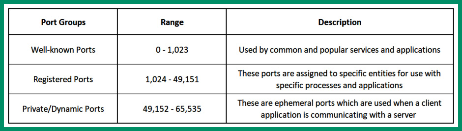
Figure 6.1 – Service port numbers
As shown in the preceding table, there are 65,535 service ports on an operating system. These services can be used with the Transmission Control Protocol (TCP) and/or User Datagram Protocol (UDP) Transport layer protocols of an operating system. An operating system will temporarily open a dynamic/ephemeral service port for sending only messages. A server that’s providing a service or resource to clients on a network will open a well-known service port number to allow inbound connections from clients. Without an open service port number on an operating system, a device will not be able to send and receive messages. As a result, the device will not be able to communicate with others on the network.
In the following sub-sections, you will discover various application and network protocols that help users share resources and communicate efficiently over a network.
File protocols
As a network professional, you will commonly discover many file-sharing applications that allow devices, clients, and servers within organizations to provide file-sharing services to users on the network. Within the networking industry, there are various application and network layer protocols that are designed with the functionality to allow file transfer between devices over a network.
File Transfer Protocol
The File Transfer Protocol (FTP) is a very common file sharing protocol that operates in a client-server model, allowing users to connect to a file server to upload and download files over a network. FTP operates on service port 20 to allow data transfer between an FTP client and the FTP server, while service port 21 is dedicated to controlling commands and functions from the FTP client and FTP server.
The following diagram shows the first phase of an FTP connection between a client and server on a network:
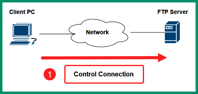
Figure 6.2 – Phase 1 of FTP
As shown in the preceding diagram, the computer with the FTP client application opens the connections to the FTP server on service port 21. Next, the client opens another connection to the server on service port 20 to transmit data traffic, as shown in the following diagram:
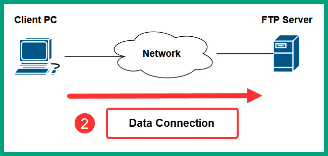
Figure 6.3 – Phase 2 of FTP
Lastly, the data is transferred from the FTP server on service port 20 to the client, as shown in the following diagram:
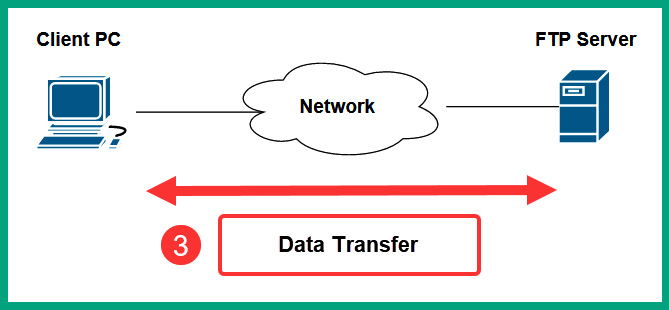
Figure 6.4 – Phase 3 of FTP
Imagine each employee within an organization only stores files on their local computers; if a user’s computer were to experience a storage drive failure or get infected with malware, there would be a high risk that the data will be lost or corrupted. Storing files on a centralized file server on a network allows employees to upload, download, and share files with others, allowing multiple people to work together on the same files. The same principle applies to file sharing between networking devices and client systems on a network. So, whenever a network professional has to update the firmware of a router or a modem, these networking devices usually support FTP as a method to transfer the firmware from a computer to the modem over a network.
Important note
FTP uses service ports 20 (data) and 21 (control) by default.
As an aspiring network professional, it’s important to consider the security of the network when implementing network services and protocols within an organization. While an FTP server is usually implemented within the internal network of a company, it’s still important to use secure protocols whenever possible to reduce the likelihood of a cyberattack. FTP is one of the many protocols that does not provide any data encryption and sends the traffic in plaintext. Therefore, if a threat actor such as a hacker can intercept the traffic that’s being exchanged between an FTP client and an FTP server, the hacker will be able to capture all the data and user credentials that were exchanged between devices. Hence, FTP is vulnerable to Man-in-the-Middle (MiTM) attacks.
SSH File Transfer Protocol
The SSH File Transfer Protocol (SFTP) allows a client to establish an encrypted tunnel using Secure Shell (SSH) to a file server that supports the SFTP protocol. Once the SSH connection is established between the client and server, both devices encapsulate the FTP packets within the SSH tunnel for file transfer over the network.
The following diagram shows a visual representation of SFTP over a network:

Figure 6.5 – SFTP
As shown in the preceding diagram, the computer establishes an SSH tunnel to the server on port 22 over the network and uses FTP to transfer files within the encrypted SSH tunnel. Using SFTP prevents a threat actor such as a hacker from identifying any confidential or sensitive data that’s being exchanged over a network. The hacker will be able to intercept the traffic, but all the packets will be encrypted and the data will be unreadable.
Important note
SFTP uses service port 22 by default.
Network professionals should always use secure protocols such as SFTP whenever possible within their organization’s networks and the internet. Without secure communication, hackers and other malicious users will be able to view our digital messages and capture confidential data. SFTP is one of the many secure protocols within the TCP/IP networking model.
File Transfer Protocol Secure
File Transfer Protocol Secure (FTPS), sometimes referred to as FTP over SSL (FTP/S), is another file transfer protocol that allows users to securely transfer files between a client and server over a network. SFTP uses Secure Sockets Layer (SSL) or Transport Layer Security (TLS) to encrypt the FTP messages that are being sent over the network between a client and server.
The client encrypts the FTP messages using SSL/TLS before placing the messages on the network to the destination FTP server. Compared to SFTP, as messages are sent across the network, there is no secure connection/tunnel; each FTPS packet is individually encrypted using SSL/TLS. Therefore, the FTP server will decrypt each FTPS message as they are received from the network and reassemble the messages into data.
However, FTPS operates on service port 990 and sometimes on service port 21. If a client on the network establishes a connection to the server on service port 990, it is considered to be implicit FTPS, which indicates the client intends to use SSL. As a result, the SSL handshakes will be exchanged between the client and server immediately.
On the other hand, if the client establishes a connection to the server on service port 21, it is known as explicit FTPS. When using explicit FTPS, the client connects to port 21 on the server and wants to use SSL with the server, additional steps are taken by sending either an AUTH SSL or AUTH TLS command from the client to the server.
Once the server receives the AUTH SSL or AUTH TLS command from the client over the network, the client and server will begin exchanging SSL handshakes and establish a secure connection. For this reason, when the client makes connections on service port 21 for FTPS, it’s called explicit FTPS as the client has the option to enable better security mechanisms when needed to transfer sensitive files.
Trivial FTP
The Trivial File Transfer Protocol (TFTP) is a connectionless, lightweight version of FTP that allows network professionals to quickly upload and download files between a client and networking device over a network. In large organizations that have many networking devices such as routers and switches, network professionals update the operating systems and firmware of these devices to fix any bugs and security issues and improve the stability of the device. Enterprise-grade networking devices allow network professionals to configure switches and routers to load their operating systems from a remote TFTP server over a network at the boot time.
While networking devices have their operating systems stored locally, Cisco routers and switches can be configured to retrieve their operating system from a TFTP server at boot time. This method allows networking professionals to download and store the latest version of the operating system on a centralized TFTP server. When a networking device such as a Cisco router is powered on, it will check for a remote TFTP server and download the operating systems over the network and load it into the memory of the router. In the future, whenever a newer version of the operating system or firmware is available, network professionals can simply download the newer version and replace the older version on the TFTP server.
Important note
TFTP uses service port 69 by default.
The following diagram shows a visual representation of using TFTP on a network:
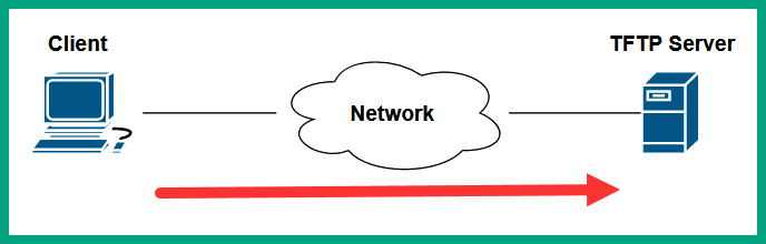
Figure 6.6 – TFTP service on a network
As shown in the preceding diagram, the client is connecting to the TFTP server on its default service port, 69, to upload or download files over the network. Being a connectionless protocol, TFTP uses UDP as the preferred Transport layer protocol, so it is lightweight and does not need acknowledgment messages when sending messages.
Server Message Block
The Service Message Block (SMB) is a common protocol that operates in a client-server model, allowing shared network resources such as printers, files, and directories to be shared in a Microsoft Windows environment.
The following are the three core functions of SMB:
- Starting, authenticating, and terminating sessions between a client and server
- Controlling access to files and printers
- Allowing applications to exchange information between devices on a network
The following diagram shows a visual representation of the client-server model of SMB:
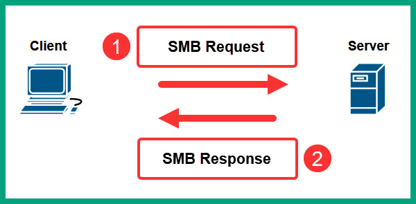
Figure 6.7 – Client-server model of SMB
As shown in the preceding diagram, the client devices send an SMB Request to the server to request the shared network resources on the server. The server responds with an SMB Response to the client, providing requesting additional information for authentication and providing access to the resources.
Important note
The SMB protocols operate on service ports 137 (UDP), 138 (UDP), and 445 (TCP).
While SMB is commonly used within a Microsoft Windows environment, Linux-based operating systems use a variation of SMB that is known as SAMBA. Lastly, Apple’s macOS also uses SMB to share network resources between devices.
In this section, you learned about various networking protocols that help devices transfer files. Next, you will how network professionals can remotely access devices over a network.
Remote access protocols
Remote access protocols are special protocols that allow IT professionals to remotely access and manage devices over a network. Within an organization, there may be hundreds of servers and networking devices that are located at different remote offices. IT professionals usually configure remote management on these devices, which allows them to remotely connect and implement new configurations or perform troubleshooting to resolve any issues. Without remote access protocols, an IT professional will always need physical access to a device to perform any configuration changes or troubleshooting.
For instance, a few years ago, I was a network engineer for a regional Internet Service Provider (ISP) and my department was responsible for monitoring and resolving any networking issues that affected the performance of the service provider’s network infrastructure and delivery of services. While working in the ISP, my team monitored networks within many different countries that had a lot of networking devices. If an issue occurs within any part of the network, whether it’s within the same country as our offices or another country, a network engineer who is assigned to the service ticket will remotely connect to various networking devices within the service provider’s network and perform troubleshooting to resolve the issues. Additionally, if any changes were to be made on the network, the same methodology applies – to remotely connect to the networking devices and administer the changes.
Using remote access protocols provides the convenience for IT professionals to centrally manage end devices, servers, and networking devices over a network. Additionally, it helps IT professionals save a lot of time from physically visiting the location of a server or network device. While remote access protocols provide a lot of conveniences, they also provide a security risk if an IT professional is using an unsecure remote access protocol to connect to a networking device. Unsecure protocols do not provide security features such as data encryption and sending messages in plaintext, allowing hackers to capture usernames and passwords.
Telnet
Telnet is an unsecure remote access protocol that allows IT professionals to remotely connect to devices such as computers, servers, networking devices, security appliances, and IoT devices. While Telnet is a legacy protocol and should not be used due to security concerns, many organizations still implement Telnet as a remote access protocol on their corporate networks.
The following screenshot shows the number of devices on the internet that have Telnet enabled for remote access:
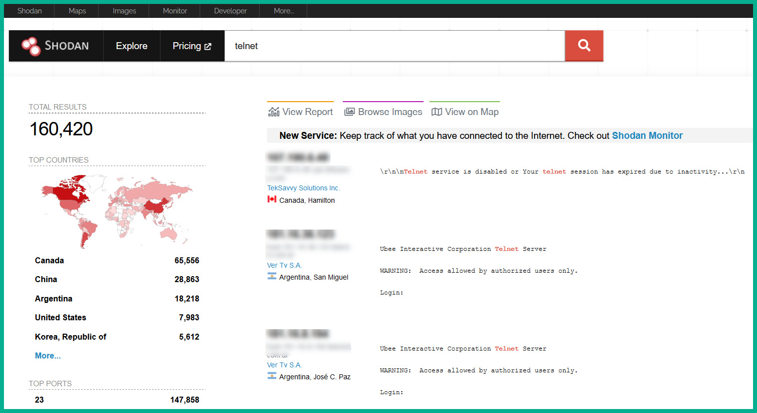
Figure 6.8 – Shodan results
Shodan is an online service used by cybersecurity professionals to determine whether their organization’s IT infrastructure is exposed to the internet. The preceding screenshot shows there are a lot of devices around the world that have Telnet enabled for remote access and management. If a hacker retrieves or guesses the correct user credentials for any device, the hacker will be able to access the target device over the internet.
Important note
Telnet uses service port 23 by default.
The following screenshot shows a reconstruction of packets that were exchanged between a client and a server using the Telnet protocol:
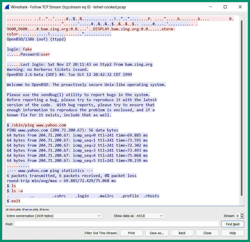
Figure 6.9 – Telnet messages
As shown in the preceding screenshot, the client and server exchanged messages and, using a packet analyzer such as Wireshark, reorganized all the Telnet messages and provided a simple overview of the communication that occurred between the client and server. The messages are displayed in plaintext because Telnet does not provide any data encryption, so it’s an unsecure remote access protocol and is not recommended for use on a network.
Secure Shell
The Secure Shell (SSH) is a secure remote access protocol that allows IT professionals to securely connect to devices over a network to perform configuration changes and troubleshooting. Unlike Telnet, SSH encrypts all the messages that are exchanged between the client and the device that’s running the SSH service, such as the networking device or the server on the network. Without SSH, it’ll be risky to use unsecure remote access protocols on the network, whereby a threat actor such as a hacker can intercept the communication and capture confidential data such as the username and password needed to access a device.
SSH encrypts all messages, so a hacker can still intercept the communication between a source and destination, but they will not be able to decrypt the message to view the secret/concealed data. One of the most common procedures when configuring a new networking device such as a router or switch is to implement a secure remote access protocol such as SSH; this allows networking professionals to manage the device over a network using a secure protocol.
Important note
SSH uses service port 22 by default.
The following screenshot shows a sample Wireshark capture between a client and server using SSH:
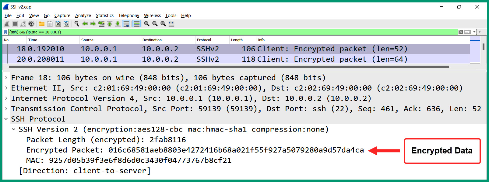
Figure 6.10 – SSH packet capture
As shown in the preceding screenshot, the client has an IP address of 10.0.0.1 and uses SSH to send encrypted messages to the server at 10.0.0.2. Wireshark helps determine the SSH version, encryption algorithm, and hashing algorithm for validating the integrity of the message, as well as the Message Authentication Code (MAC) value and the actual encrypted message/data. Therefore, the information displayed on the Wireshark interface is the same information that a hacker will be able to view and capture while the data is encrypted and safe.
Remote Desktop Protocol
Within a Microsoft Windows environment, IT professionals enable Remote Desktop Protocol (RDP), a native secure remote access protocol that is built into Microsoft Windows operating systems. Using RDP within an organization allows IT professionals to remotely manage Windows servers and desktop devices using a Graphical User Interface (GUI). This differs from SSH and Telnet, which provide a Command-Line Interface (CLI).
Important note
RDP operates on service port 3389.
The following screenshot shows a packet capture of RDP messages that were exchanged between two Microsoft Windows devices over a network:
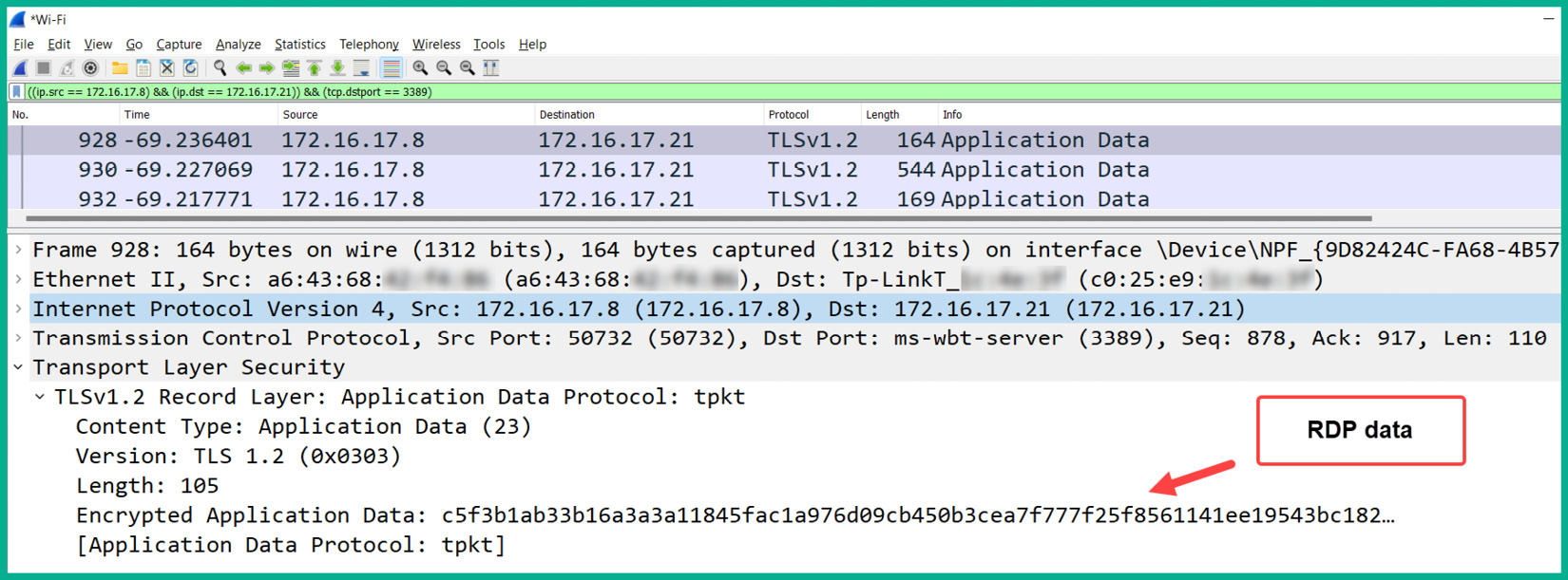
Figure 6.11 – RDP packet capture
As shown in the preceding screenshot, the client device has an IP address of 172.16.17.8 and it sends RDP messages to another host with an IP address of 172.16.17.21. The RDP message is encrypted using TLS, a security protocol that provides data security and privacy on a network. Furthermore, the packet capture reveals that the RDP messages are encrypted and prevent anyone from viewing the confidential data that’s exchanged between the hosts on the network.
Email protocols
The way people communicate with each other has changed a lot over the years. Initially, a person would write a letter using the traditional method with a pen and paper or use a typewriter. Once the letter was written, it was enclosed within an envelope where the sender’s information and destination addresses were inserted with a postal stamp. Then, it was given to the postal service organization for delivery to the intended recipient. Sending a traditional mail or package to someone can take some time before it arrives at the destination.
In today’s world, sending a traditional letter to someone is almost replaced with electronic mail (email), which allows a sender to write a message using their computer or smartphone and send it over a network to the destination email address. Emails are typically delivered to their destination addresses within a few minutes compared to a traditional letter, where a courier service is used. Emails are commonly used to send letters, notices, memorandums, and share files as attachments between users. To ensure emails are transported and delivered over a network, various email protocols help devices format messages for transportation and delivery between a sender and destination address.
The SMTP is an email protocol that is used for sending emails from clients to email servers, and email servers to other email servers. The following process provides an overview of each phase of sending an email between a sender and destination:
- When a user wants to send an email message to another person, the sender uses an email application such as Microsoft Outlook to compose and send the message.
- The email application on the sender’s computer uses SMTP to establish a connection to the sender’s email server. When the connection is established, the email application uses SMTP to forward the email message to the sender’s email server, which has service port 25 open by default.
- When the sender’s email server receives the email message, it also uses SMTP to forward the email message to the recipient’s email server, which has service port 25 open by default.
- When the email arrives on the recipient’s email server, the server uses SMTP to send the message to the email application on the intended recipient’s device.
The following diagram shows a visual representation of using SMTP to send emails over a network:
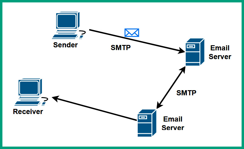
Figure 6.12 – SMTP process
The Post Office Protocol (POP) is a common email protocol that allows email clients such as Microsoft Outlook to download messages from email servers over a network. The email servers that use the POP service passively listen on TCP service port 110 for inbound requests from email client applications. Once a TCP connection is made between the client application and the email server on service port 110, the client downloads the email messages from the mailbox to the client. Once the emails have been downloaded, the email messages are deleted from the email server.
The following diagram shows a visual representation of the POP operations:
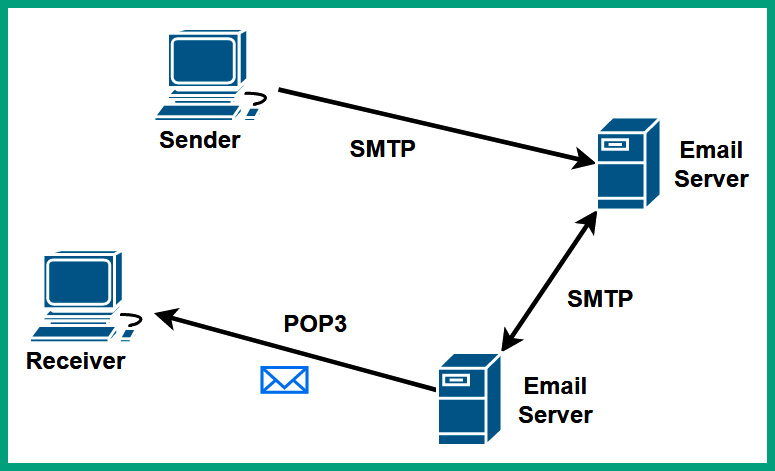
Figure 6.13 – POP operations
As POP deletes the email messages from the email server after downloading them onto the client device, there is no centralized location for storing the messages on a network. Hence, POP is not recommended for organizations that need a centralized backup solution for their resources.
The Internet Message Access Protocol (IMAP) is another common email protocol that allows email clients such as Microsoft Outlook to synchronize the email messages between the client application and email server via service port 143 by default over a network.
The following diagram shows a visual representation of IMAP on a network:
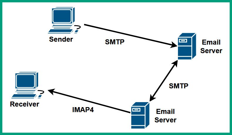
Figure 6.14 – IMAP operations
When using IMAP on a network, the email messages are kept on the email server until they are manually deleted or removed from a user’s mailbox on the server. Email protocols such as SMTP, POP, and IMAP do not encrypt the messages and send them in plaintext over a network, so a hacker who is intercepting the messages over a network will be able to view the content of emails exchanged between users.
Important note
POP version 3 (POP3) and IMAP version 4 (IMAP4) are commonly used on networks.
The following screenshot shows a TCP stream of SMTP messages over a network within Wireshark:
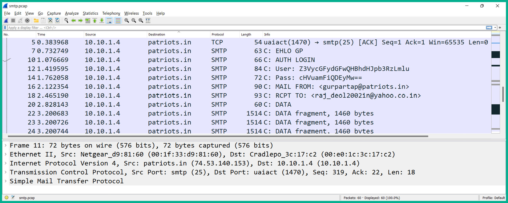
Figure 6.15 – Email message
As shown in the preceding screenshot, the Info column reveals sensitive information found within some SMTP packets, such as the username and password used by the client to access the email server on the network.
The following screenshot shows the TCP stream that was reassembled by Wireshark:
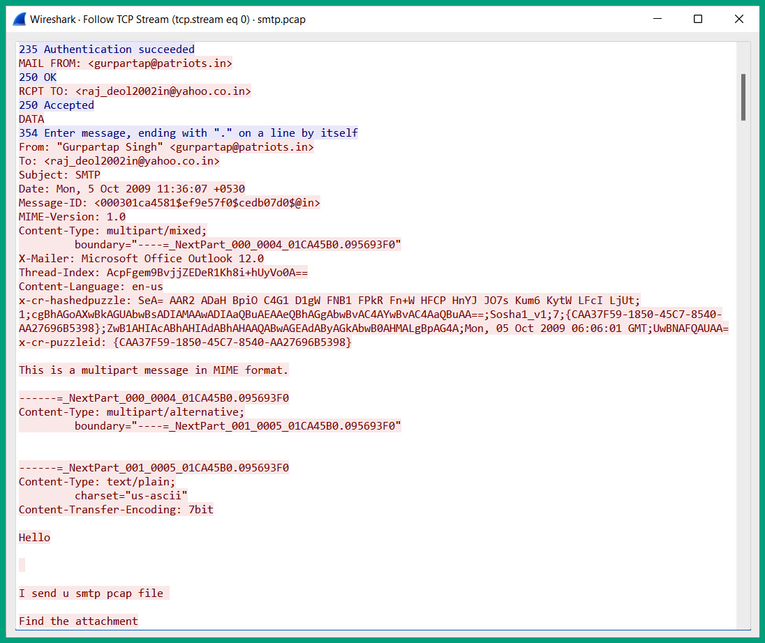
Figure 6.16 – Reassembled TCP stream
As shown in the preceding screenshot, Wireshark was able to reassemble all the data found within all SMTP packets exchanged between the client and the server to produce a TCP stream showing the plaintext messages that were exchanged in a dialog format. The messages displayed in red are sent from the client to the email server, while the messages in blue are messages from the email server to the client on the network.
Using unsecure protocols is not recommended due to a lack of security features such as data encryption to provide confidentiality and privacy. To solve the issue with security, Simple Mail Transfer Protocol Secure (SMTPS) is a secure email protocol that uses TLS to encrypt outbound emails over a network and uses service port number 587 by default. Additionally, the Post Office Protocol Secure (POPS) is a secure email protocol that uses SSL to encrypt the email messages that are being downloaded from an email server to an email application on the client and uses port 995 by default. Lastly, the Internet Message Access Protocol Secure (IMAPS) is a secure email protocol that operates on service port number 993 and uses SSL to encrypt the email messages between the client and server during the synchronization process.
HTTP and HTTPS
When communicating with a web server on a network or the internet, a user will typically open a web browser application on their device that uses HTTP to create a message that is recognizable to the web application running on the web server. HTTP is an unsecure protocol that does not provide confidentiality or data privacy and sends messages in plaintext over a network to a web server that uses service port number 80 by default.
The following screenshot shows an HTTP GET message that was sent from a client to a web server:
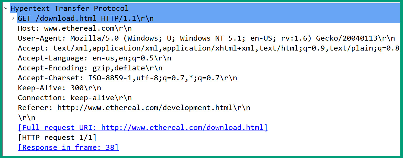
Figure 6.17 – HTTP message
As shown in the preceding screenshot, Wireshark can display the contents within the HTTP section of the packet between the client and web server on the network; HTTP does not encrypt the messages and sends them in plaintext. To resolve the security concerns of HTTP, it’s recommended to use HTTP over SSL (HTTPS), which is a secure version of HTTP that establishes a secure connection between the web browser and web server over the network while using service port number 443 by default.
Important note
HTTPS can use either SSL or TLS when connecting to a web server.
The following screenshot shows a client connecting to a web server using HTTP:
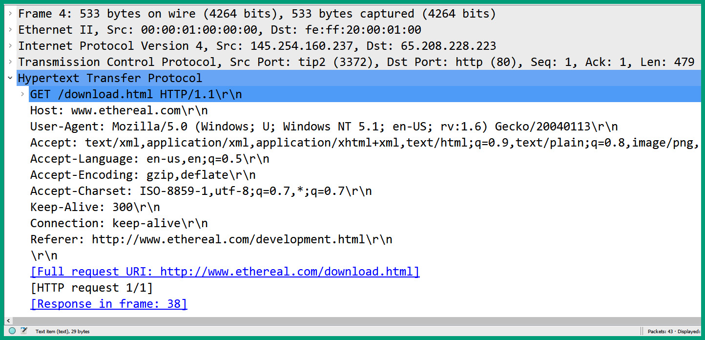
Figure 6.18 – HTTP GET message
As shown in the preceding screenshot, the client device sends the HTTP GET message to service port 80 on the server and can see the contents of the message in plaintext. As network professionals and hackers will be able to determine the location of the resource that’s being requested by the client device on the internet, it’s not recommended to use unsecure protocols on a network due to data privacy concerns.
The following screenshot shows the contents of an HTTPS packet that was captured while it was sent from a client to a web server:
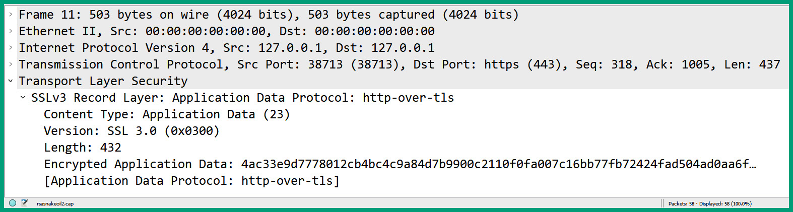
Figure 6.19 – HTTPS message
As shown in the preceding screenshot, the contents of the HTTPS message are unreadable because it’s encrypted, unlike HTTP. Using HTTPS allows users to securely connect to web servers and exchange messages between their web browser application and the web server over the network. Try to always use secure protocols such as HTTPS whenever possible to ensure data security and privacy.
With that, you’ve discovered common networking protocols that are used to send and retrieve information between web applications and clients on a network. Next, you will explore various data database protocols.
SQL database protocols
Within many medium to large organizations, there are dedicated servers that host database applications that provide database services to clients and users on the networks; these servers are commonly referred to as database servers. A database is simply an application that stores large amounts of data in a structured format. For instance, educational institutions need an application to store their student enrollment information in an understandable format. Imagine if each student’s information were stored on individual documents without any fields and structure; anyone who is searching for a specific student file will experience difficulty. However, a database allows an administrator to create tables with fields to hold specific information.
Clients on a network simply send queries to the database server to retrieve specific information. For instance, an employee within a financial institution can send a query to their database server to retrieve the records of all people who opened an account within a specific period. Furthermore, the employee can be very granular with queries such as filtering age group, time range, gender, and so on. Database applications operate in a client-server model, whereby the user has the database client-side application installed on their computer, which connects to the database application that’s running on the database server over the network.
The following are common database application protocols and their operating port numbers:
- SQL Server operates on service port 1433
- SQLNet operates on service port 1521
- MySQL operates on service port 3306
The following screenshot shows a packet sent to a MySQL server:
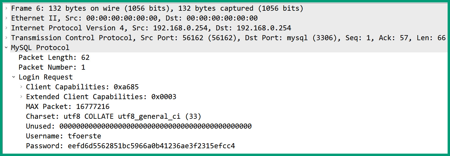
Figure 6.20 – MySQL packet
As shown in the preceding screenshot, the client sends the username and password hash to the MySQL server on port 3306. Furthermore, notice that the user credentials are sent in plaintext as the MySQL database protocol does not encrypt messages by default.
Lightweight Directory Access Protocol
The Lightweight Directory Access Protocol (LDAP) is a common network protocol that is used to perform operations such as read, write, and query on a directory server over a network. A common directory service is the Active Directory Domain Service (AD DS) on a Microsoft Windows Server operating system. Active Directory allows IT professionals to centrally manage all users and connected devices on a Windows domain within an organization. Simply put, IT professionals join all computers on the Windows domain and create the users’ accounts on Active Directory. Additionally, Active Directory allows policies to be applied to users, groups, and computer accounts on the Windows domain.
Important note
The Windows server that is running the AD DS role is commonly referred to as the Domain Controller (DC).
To gain a better idea of how LDAP works, the following steps provide details of when a user is connecting to a Windows domain using Active Directory:
- The user powers on their computer and is prompted to log in using their domain user account.
- The user enters their username and password on the Windows client computer.
- The Windows client computer converts the user’s password into a New Technology LAN Manager (NTLM) hash value because the Microsoft Windows operating system does not store users’ passwords in plaintext.
- The user’s username and password hash is sent to the DC using LDAP.
- The DC checks the Active Directory service to determine the authenticity of the user’s credentials and applies policies.
- The DC informs the Windows client device on whether to allow the user to log in and the policies to apply.
The communication that occurs between the Windows client device and the DC uses LDAP by default. However, LDAP is an unsecure network protocol that operates on service port 389 by default on directory servers.
The following screenshot shows the information captured from an LDAP message on a network:
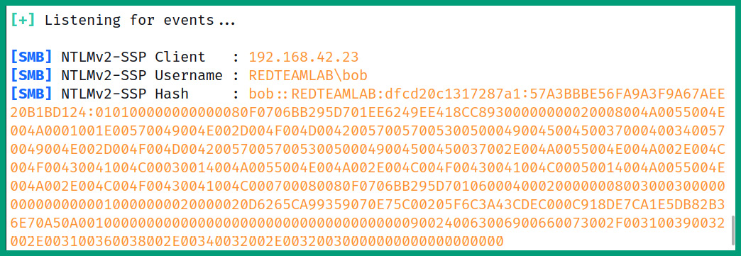
Figure 6.21 – LDAP message
As shown in the preceding screenshot, the contents of an LDAP message from a client to a DC were captured and the data was sent in plaintext. A hacker who is intercepting the packets on a network will be able to capture the client’s source IP address, the domain name, and the username and password hash of the user.
Important note
LDAP uses the X.500 standard, which defines how information is stored and organized within a directory server.
Since LDAP is an unsecure protocol that does not provide confidentiality and data security, it’s recommended to use LDAP Secure (LDAPS), which uses SSL/TLS for data encryption to ensure privacy on a network. LDAPS operates on service port 636 by default.
Syslog
Networking devices, servers, and even end devices generate log messages that contain information and critical details about events that occur. Network professionals use the information found within log messages to identify if a problem has occurred and what caused the problem. Since each networking device generates a log message, this means a network professional will need to manually log into a device to view the logs for that device only. This process can be very time-consuming and inefficient.
Many networking devices, servers, and end devices support a common network protocol that allows them to forward their log messages over a network to a centralized logging server. This protocol is known as Syslog. The Syslog protocol allows devices to generate logs for events that occur on a device. For example, if an interface on a router has been disabled or enabled, a Syslog message is created that contains all the necessary details about the event.
The following is the default format of a Syslog message that is generated by Cisco devices:
seq no: timestamp: %facility-severity-MNEMONIC: description
The following is a breakdown of each component of a Syslog message:
- seq no: Represents the sequence number that is assigned to the log message.
- timestamp: Includes the date and time the message was generated by the device. The date and timestamp are taken from the system clock on the host device.
- facility: Represents what the log message is referencing on the event that has occurred, such as the source of the problem or protocol.
- severity: Includes a severity code that helps network professionals determine the importance of the event.
- MNEMONIC: Inserts text that is uniquely used to describe the event.
- description: Contains a brief description of the event.
The following is an example of a Syslog message generated by a Cisco device:
*Apr 28, 15:53:58.5353: %LINEPROTO-5-UPDOWN: Line protocol on Interface GigabitEthernet0/1, changed state to up
The following table contains the Syslog severity levels, their names, and descriptions:
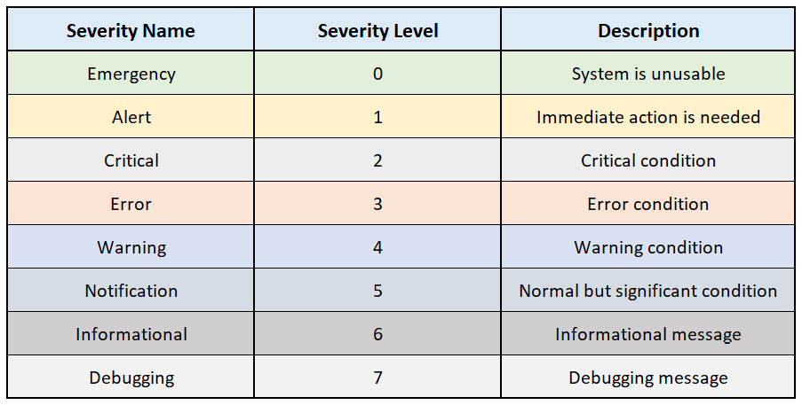
Figure 6.22 – Syslog severity levels
The Syslog protocol uses UDP service port number 514 by default over a network. Keep in mind that Syslog is used to gather logging information that helps network professionals with monitoring and troubleshooting issues within an organization. Syslog allows network professionals to configure devices to send their log messages to a specific logging destination, such as a centralized logging server.
Session Initiation Protocol
Voice over IP (VoIP) is a very common technology that allows organizations to implement a telephone system on their existing TCP/IP network. The telephones have an IP address assigned on the network that converts a person’s voice into a digital signal in the form of packets to be transmitted over a network. The IP phones communicate with a Unified Communication Server (UCS) that contains the call routing features, voicemail settings, hunt groups, and other calling functions that are needed by the organization.
One of the major benefits of using a VoIP system within an organization is the cost efficiency of the telephone charges. An employee can simply pick up their IP phone and dial the extension number of another employee within the same organization and won’t be billed for the internal call as the communication is occurring within the organization’s network. When an employee uses their IP phone to call another employee, the IP phone uses the Session Initiation Protocol (SIP), a common network protocol that provides real-time transmission of both voice and video traffic over a network.
Important note
SIP operates on service port 5060 by default and does not encrypt messages over the network. However, there’s a secure version of SIP that operates on service port 5051.
Real-time protocols such as SIP use UDP as their preferred Transport layer protocol as it provides faster transmission and low overhead on the network compared to TCP. However, since UDP messages have a high priority to be discarded on a congested network, network professionals usually implement Quality of Service (QoS) technologies on the network to guarantee the allocation of network bandwidth to specific traffic types such as VoIP and Video over IP.
Next, you will discover common networking protocol types such as TCP, UDP, and ICMP.
Network protocol types
There are so many protocols and protocol types on a network and learning them can take a lifetime to master. However, as an aspiring network professional, it’s important to understand the fundamentals of common network protocol types that are found within many organizations. Network protocol types are simply the set of rules that are used to describe how a device such as a computer communicates with another device over a network. If two devices are used, whether they are the same type of devices or different, both systems need to negotiate on a common set of rules. These common rules are referred to as the network protocol type.
Over the next few sub-sections, you will learn about the fundamentals of ICMP, TCP, and UDP.
Internet Control Message Protocol
Internet Control Message Protocol (ICMP), defined by RFC 792, is typically used to provide error reporting on a network. Common networking tools such as Ping and Traceroute are built into many operating systems and allow network professionals to invoke ICMP to check end-to-end connectivity between hosts on a network, identify the path a packet is traveling between a source and destination, and even measure the latency between hops on a network.
The following table provides a breakdown of each ICMP type by name, code, and description:
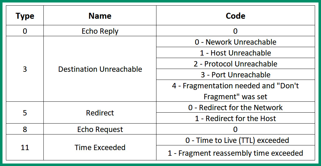
Figure 6.23 – ICMP codes and types
As shown in the preceding table, various ICMP codes and types are inserted within an ICMP packet. For instance, the following screenshot shows a connectivity test between my computer and Google’s DNS server on the internet:
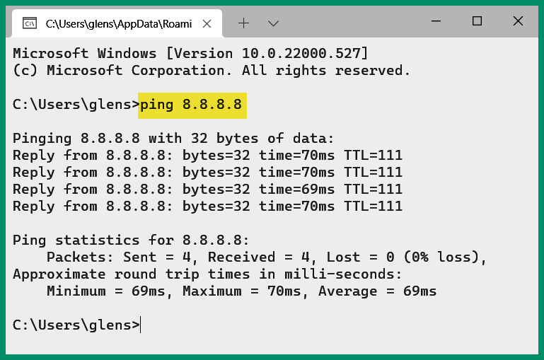
Figure 6.24 – Using ping to test connectivity
As shown in the preceding screenshot, the local host sent four ICMP Echo Request messages to Google’s DNS server on the network and received four ICMP Echo Reply messages. The following screenshot shows the ICMP type and code value for the ICMP Echo Request message with the source and destination IP addresses and port numbers:
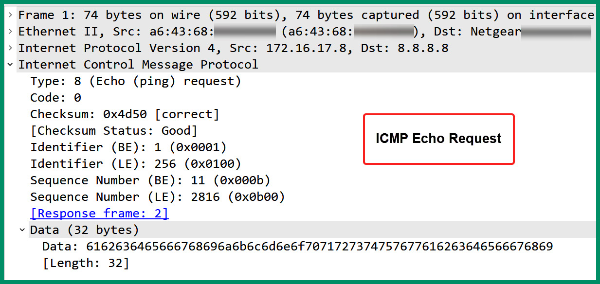
Figure 6.25 – ICMP Echo Request message
For each ICMP Echo Request message that’s received and processed by a host, an ICMP Echo Reply is returned. The following screenshot shows the ICMP type and code values within an ICMP Echo Reply message:
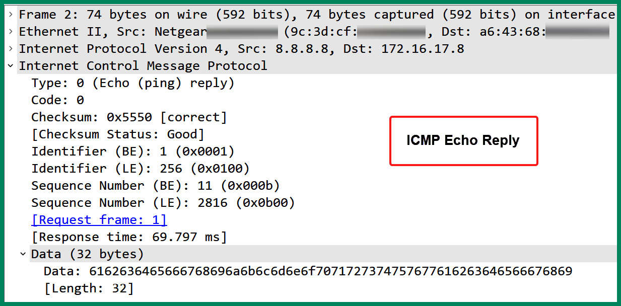
Figure 6.26 – ICMP Echo Reply message
Network professionals use various free and commercial software-based tools that use ICMP to assist with identifying any potential issues on a network and resolving them.
TCP
TCP, defined by RFC 793, is a connection-oriented protocol that operates at the Transport layer of both the OSI and TCP/IP networking models. It is designed to provide reliable transportation of the datagrams over a network by establishing a TCP 3-way handshake between the source and destination hosts before exchanging data between devices. For each message sent between devices on the network, the receiver responds with a TCP acknowledgment (ACK) message that indicates the message was received. If the sender does not receive an ACK message from the intended destination after a predefined time, the sender will attempt to retransmit the message again.
UDP
UDP, defined by RFC 768, is a connectionless protocol that operates at the Transport layer of both the OSI and TCP/IP networking models. Unlike TCP, UDP does not provide any guarantee or reassurance of the delivery of datagrams across a network. Therefore, if an application layer protocol uses UDP as the preferred Transport layer protocol and the packet is discarded on the network, the sender will retransmit the packet.
As quickly as the application layer is sending data down the TCP/IP networking model, UDP will be forwarding those messages quickly further down the model and then onto the network. UDP is not concerned about whether the messages are delivered to the intended destination. However, it provides faster data transmission and less overhead on the network compared to TCP.
Having completed this section, you have learned about common network protocol types and their characteristics. Next, you will explore common network services and how they are used on a network.
Network services
As you progress further into your networking journey, you will be exposed to common network services that organizations rely upon each day to ensure their devices can exchange messages over a network. Some of these network services help organizations synchronize time on all devices within their network, while other network services provide IP addressing configurations to clients that are connecting to a network. In this section, you will learn about the characteristics and fundamentals of common networks that are implemented within organizations by network professionals to provide essential network services to users.
Network Time Protocol
Network Time Protocol (NTP) is a network protocol that allows IT professionals to configure devices to synchronize their system clock to the same time on a network. NTP operates on a client-server model that uses UDP service port 123 by default. Without NTP on a network, IT professionals will need to manually configure the time on each device such as computers, servers, networking devices, and security appliances within the organization. This process can be very time consuming, which can lead to misconfigurations and mismatches in the time set on many devices.
When time is synchronized on the system clocks on all devices, it ensures all devices have the same time set. This is important for ensuring automated tasks are executed on time and in the proper sequence. Imagine if IT professionals configure various tasks on servers and systems to be undertaken automatically at a specific time of day for each day of the week. If the time on the devices is not accurate, the tasks will not be performed when needed. Furthermore, when a device is generating Syslog messages, it’s important to include the time and date in each log message to help network professionals determine when an event or incident has occurred. Without time synchronization, the time inserted into Syslog messages will not correlate with the events on other networking devices. This will create a challenge for network professionals to determine the actual sequence of events that occurred on the network.
Important note
NTP is an unsecure protocol that allows hackers to exploit its security vulnerabilities. However, NTP allows authentication between an NTP server and NTP clients over a network.
The following diagram shows the NTP architecture and hierarchical structure:
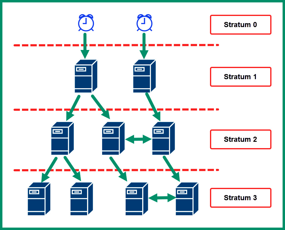
Figure 6.27 – NTP hierarchical structure
As shown in the preceding diagram, the NTP hierarchical structure is made up of clients, servers, and stratum levels. The NTP servers are devices that provide the time for NTP clients on a network.
Important note
The NTP stratum levels range from 0 to 15, where level 0 contains the authoritative sources.
Each stratum level 0 contains the primary time servers and are known as the authoritative sources on the network that have the most accurate time. Servers at stratum level 1 synchronize their time clocks with devices on stratum 0, while devices on stratum 2 synchronize their time with those devices on stratum 1 and so on.
Dynamic Host Configuration Protocol
The Dynamic Host Configuration Protocol (DHCP) is a common network protocol and service that allows network professionals to automatically distribute IP addresses to client devices on a network. When an end device such as a computer or smartphone is connected to a network, it requires an IP address, subnet mask, default gateway address, and Domain Name System (DNS) server address. These IP addresses allow the client to communicate with devices on the same network and remote networks.
Imagine if network professionals have to statically/manually assign IP addresses to each device that’s connecting to their organization’s network; the process will be time-consuming and lead to duplication of IP address assignment. To help simplify the process of distributing IP addresses on a network, network professionals implement a DHCP server, which allows them to configure the following:
- Scope: The range of IP addresses (pool)
- Exclusion ranges: The IP addresses that should not be distributed on the network
- Reservation: Reserves IP addresses from the pool
- Dynamic assignment: Dynamically assigns an IP address to a client on the network
- Static assignment: Statically configures an IP address on a client
- Lease time: Sets the time that the client can use the IP address given from the DHCP server
- Scope options: Additional operations that can be configured when creating the scope
- Available leases: Identifies the available lease time for an IP address
Whenever a client device such as a computer connects to a network, it will seek a DHCP server on the network to retrieve IP addresses to communicate with other hosts on the same network.
Important note
A DHCP client sends a DHCP message from a source service port of 68. The DHCP server operates on service port 67 by default.
To gain a better idea of the DHCP process, the following steps outline the DHCP 4-way handshake that occurs when a client connects to a network with an active DHCP server:
- The client connects to the network and sends a DHCP Discover message, seeking a DHCP server on the network:
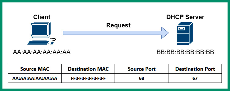
Figure 6.28 – DHCP Discover message
As shown in the preceding diagram, the client includes its source Media Access Control (MAC) address and source port number, which is 68. The client inserts the destination MAC address as FF:FF:FF:FF:FF:FF with the broadcast MAC address for a Layer 2 network and the destination port number, which is 67. The source IP address on the packet is left blank while the destination IP address is set to 255.255.255.255.
- Next, the DHCP server responds with a DHCP Offer message, which contains the IP address needed by the client for communication on the network:
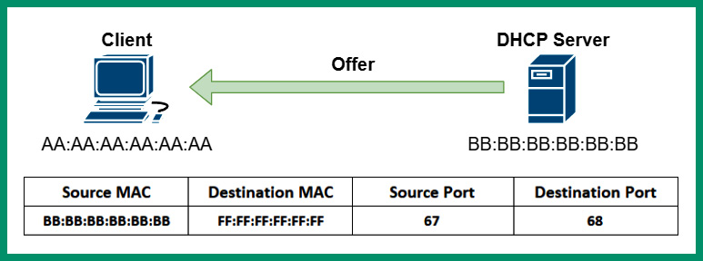
Figure 6.29 – DHCP Offer message
As shown in the preceding diagram, the DHCP Offer message is sent from the DHCP server to the client on the network. The DHCP Offer message contains the source MAC address and source port number 67 of the DHCP server. This message also contains the destination MAC and destination port number 68 of the client on the network.
Important note
The DHCP Offer message is sometimes sent as unicast or broadcast to the client on the network.
- Next, the client sends a DHCP Request message to the DHCP server, indicating that it will use the IP addresses from the previous message:

Figure 6.30 – DHCP Request message
As shown in the preceding diagram, the client sends a Layer 2 broadcast message to the DHCP server on the network, even though the client knows the MAC address of the DHCP server from the DHCP Offer packet.
- Lastly, the DHCP server responds with a DHCP Acknowledgment unicast message to confirm the client can use the IP address provided from the addressing pool on the server:
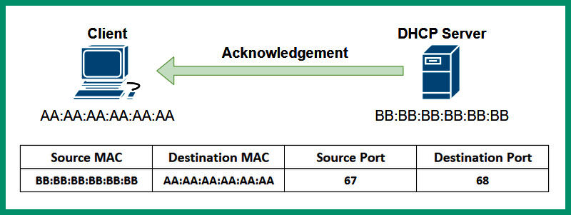
Figure 6.31 – DHCP Acknowledgement message
The client is allowed to use the IP addresses provided by the DHCP server for the duration of the lease. If the client wants to extend the lease of communication on the network, the client can send a DHCP Request (unicast) message to the DHCP server to request the renewal of the lease.
What if a client connects to the organization’s network but the DHCP server is located on another IP subnet? How will the client be able to get the IP addresses from the server? Sometimes, network professionals will configure a DHCP server with multiple address pools and implement it in a centralized location. However, when a client connects to a network, it will send a DHCP Discover message, which is only broadcast to a Layer 2 network. This means that any Layer 2 broadcast messages will not be able to propagate beyond a router.
The following diagram shows a router blocking a DHCP Discover message from propagating to another network:
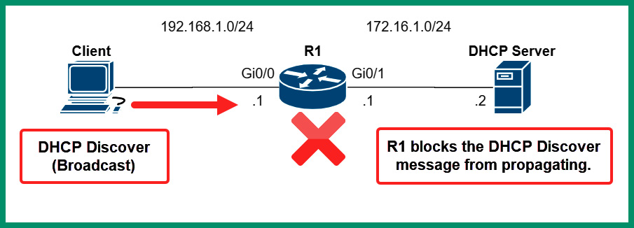
Figure 6.32 – Router blocks Layer 2 broadcast message
As shown in the preceding diagram, routers and other Layer 3 devices do not propagate Layer 2 broadcast messages beyond their source network. As a result, the DHCP Discover message from the client will not be able to reach the DHCP server on another network.
To solve this issue, configuring the router to be a DHCP Relay agent will allow the router to forward DHCP messages between clients and DHCP servers over a network, as shown here:
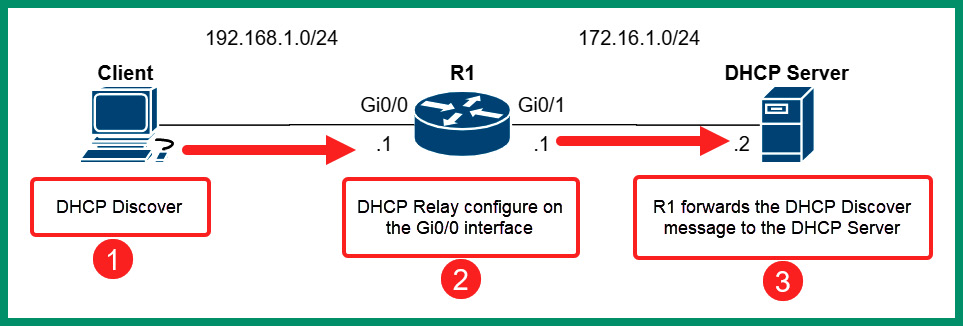
Figure 6.33 – DHCP Relay agent
The GigabitEthernet 0/0 interface on the router is configured with the following configurations to allow the router to relay the DHCP messages between the 192.168.1.0/24 network and the DHCP server:
R1(config)# interface GigabitEthernet 0/0
R1(config-if)# ip helper-address 172.16.1.2
R1(config-if)# exit
Keep in mind that the ip helper-address command is applied to the interface on the router that receives DHCP Discover messages from clients.
DNS
DNS is a very popular network protocol that allows a device to resolve a Fully Qualified Domain Name (FQDN) or a hostname to an IP address over a network. As you know already, each device on a network has an IP address that allows end-to-end communication between hosts. Imagine if you need to remember the IP address of each web server on the internet that you want to visit – it will be quite challenging to remember these logical addresses.
What if a server’s IP address has changed and you don’t know the new IP address? How will you connect to the server to access the resources? Using DNS allows network professionals to implement a DNS server on a network. This is like a directory that contains a listening of various hostnames that maps to IP addresses, similar to a traditional telephone directory, which contains a list of people’s names and their telephone numbers.
The following diagram shows a typical DNS transaction between a client and DNS server:
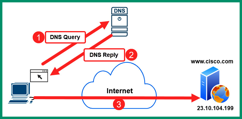
Figure 6.34 – DNS operations
The following is a breakdown of the DNS operations shown in the preceding diagram:
- The client wants to establish a connection to www.cisco.com but does not know the IP address of the web server. Therefore, the client sends a DNS Query message to the DNS server on service port 53, requesting the IP address of www.cisco.com.
- The DNS server receives this DNS Query and performs a lookup within its database and finds the record. The DNS server responds with a DNS Reply that contains the IP address of www.cisco.com.
- The client receives the DNS Reply information and connects to the IP address found in the response from the DNS server.
Important note
DNS servers use port UDP port 53 by default. However, a DNS server can exchange zone records with another DNS server by using TCP port 53.
Within a DNS server, network professionals can create various types of records containing specific IP addressing information. The following are a list of record types and their purpose:
- Address (A versus AAAA): The A record maps a hostname to an IPv4 address, while the AAAA record maps a hostname to an IPv6 address
- Canonical name (CNAME): The CNAME record allows an alias to be mapped to a domain name
- Mail Exchange (MX): The MX records contain the addresses of mail exchangers on a domain
- Start of Authority (SOA): The SOA record specifies the authority of the domain
- Pointer (PTR): The PTR record maps an IP address to a hostname
- Text (TXT): The TXT record contains text information that helps a domain owner validate ownership of a domain
- Service (SRV): The SRV record contains the service records for the domain
- Name Server (NS): The NS record contains the name servers for a domain
The following screenshot shows an example of performing a DNS lookup using the native nslookup tool within a Microsoft Windows operating system:
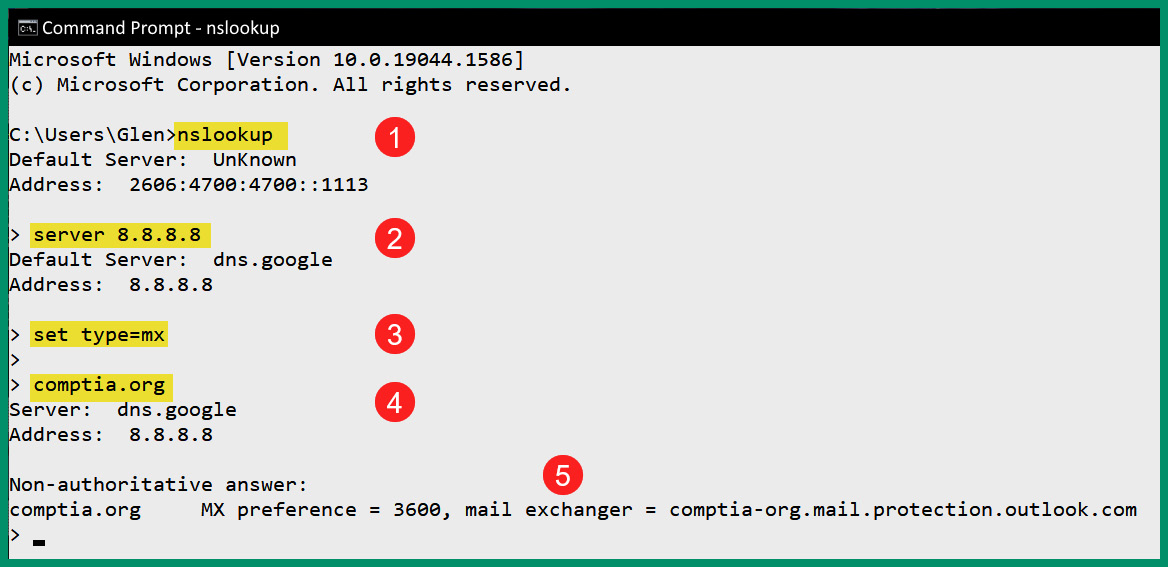
Figure 6.35 – DNS lookup
As shown in the preceding screenshot, the nslookup tool allows network professionals to troubleshoot DNS-related issues on a network. The following is a breakdown of each step shown in the preceding screenshot:
- When the nslookup command is entered in the Windows Command Prompt, it provides the current DNS server that’s configured for the host device. The address information that’s returned is retrieved from the configurations of the host device.
- Using the server <ip address/hostname> command allows the network professional to specify another DNS server to send queries while using nslookup.
- Next, the set type command is used with a DNS record type to indicate which record type to query.
- Lastly, entering a domain name such as comptia.org will send the query to 8.8.8.8 for the MX record type.
- The results indicate the information was retrieved from a non-authoritative source/server and the hostname (or IP address) of CompTIA’s email server(s) were found.
Important note
An authoritative DNS server is the final holder of an IP address for a domain name or hostname on a network. The authoritative DNS server for a domain contains the original DNS records that are associated with a domain. However, the recursive DNS server or non-authoritative DNS server does not hold the original DNS records for a domain but queries an authoritative server when needed.
Each domain name that’s available on the internet contains the root (.) and a Top-Level Domain (TLD) such as .com, .net, or .org within the name, such as cisco.com. However, hostnames are usually assigned to servers such as www.cisco.com. This is commonly referred to as an FQDN since it contains a TLD, the hostname, and the domain. Using an FQDN allows network professionals and devices to specify the location of a device on a network.
The following diagram shows an example of a global hierarchy of root DNS servers, which contains the record for their corresponding TLDs:
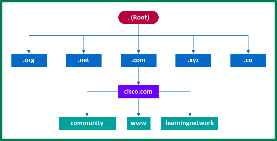
Figure 6.36 – Root DNS servers
As shown in the preceding diagram, the .com root DNS server contains all the DNS information about all the registered domain names that use the .com TLD. The .com root DNS server contains the DNS information for the cisco.com domain and its hostnames.
There are many trusted DNS servers on the internet that provide improved performance, speed, and security. The following are some examples of trusted DNS servers:
- Cloudflare DNS: https://1.1.1.1/
- Quad9 DNS: https://www.quad9.net/
- OpenDNS: https://www.opendns.com/
- Google Public DNS: https://developers.google.com/speed/public-dns
Keep in mind that you should always use trusted DNS servers whenever possible as they provide improved performance on hostname resolution and security features to filter malware and malicious websites.
Simple Network Management Protocol
The Simple Network Management Protocol (SNMP) is a common network protocol that allows network professionals to remotely manage and monitor networking devices, security appliances, and servers within their organization. SNMP helps network professionals collect information about the performance and status of a device to determine whether an issue exists, as well as how long the issue has been occurring based on historical data.
When working with SNMP, three main components need to work together to create a Network Management System (NMS):
- Manager
- Agent
- Management Information Based (MIB)
The Manager is an application that’s installed on the network professional’s computer or centrally on a server. The manager has the role and function to both collect information and make configurations on devices that are running the agent. The manager can retrieve information from agents on the network by sending an SNMP GET message that instructs the agent to respond with the requested information. Additionally, the manager sends SNMP SET messages to an agent when configuration changes are needed.
The following diagram shows a simple representation of SNMP messages on a network:
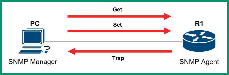
Figure 6.37 – SNMP messages
The SNMP agent is configured on the networking device, such as a switch or router. The SNMP agent is the actual component on the networking device that communicates with the SNMP manager application and vice versa. The MIB is a database that contains the information needed by the agent to find and retrieve data from a device. Simply put, the network professionals use the manager to retrieve information from a device that’s running an SNMP agent. The SNMP agent uses MIB to locate the requested information within the networking device and responds to the agent with the collected data.
Important note
SNMP operates on UDP service port 161 by default. However, the SNMP manager uses UDP service port 162.
The following are the three current versions of SNMP:
- SNMPv1: Has bad security features such as no data encryption or authentication mechanisms
- SNMPv2: This version of SNMP also contains bad security features
- SNMPv3: Supports data encryption and authentication
Having completed this section, you have learned about various network services, along with their role and functions on a network. In the next section, you will learn how to analyze various traffic and protocol types on a network.
Lab – analyzing FTP packets
In this hands-on exercise, you will learn how to analyze FTP packets using Wireshark. To get started with this exercise, follow these steps:
- Go to https://wiki.wireshark.org/SampleCaptures and download the iseries.cap file, as shown here:
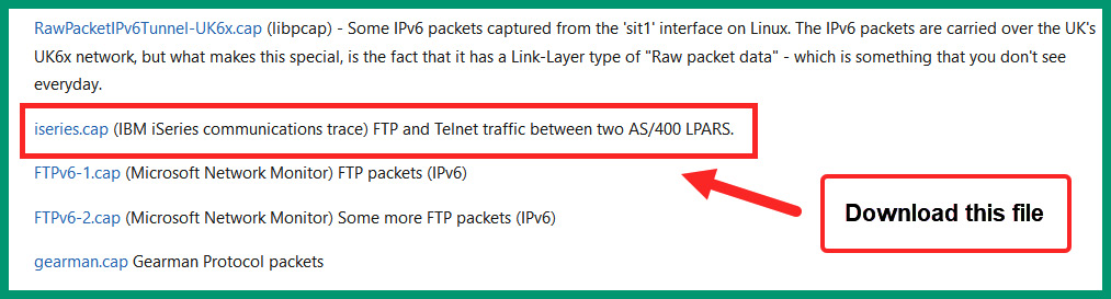
Figure 6.38 – FTP sample file
- Next, launch the Wireshark application on your computer and click on File | Open, as shown here:
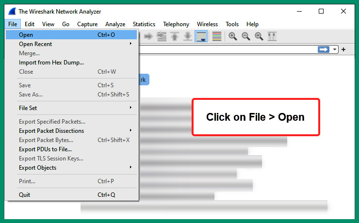
Figure 6.39 – Wireshark
- Next, the Open Capture File window will appear. Simply navigate to the location where the iseries.cap file is stored, select the file, and click on Open:
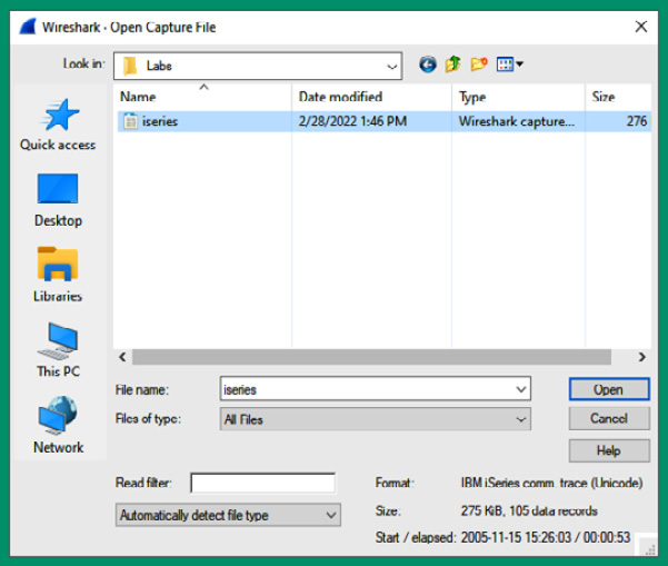
Figure 6.40 – Loading a .pcap file
- Next, Wireshark loads all the information found within the captured packets and shows the source and destination IP addresses, source and destination service port numbers, protocols, and the data found in each packet:
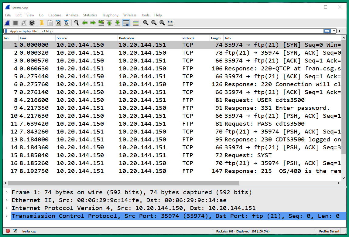
Figure 6.41 – Network packets
- In the Display Filter bar on Wireshark, type ftp and hit Enter to filter all the FTP packets within the capture, as shown here:
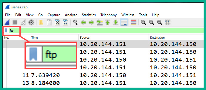
Figure 6.42 – Filtering FTP packets

Figure 6.43 – FTP packets
As shown in the preceding screenshot, sensitive information is shown within the Info column of each FTP packet, such as the user credentials sent from the client to the FTP server on the network and the step-by-step actions performed between each device.
- Next, select packet #8 to display the packet details and the data found within the Application layer of the packet, as shown here:
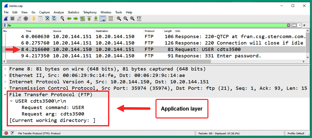
Figure 6.44 – Analyzing FTP packets
As shown in the preceding screenshot, the username was sent in plaintext to the server on the network. Additionally, you can see the source and destination IP addresses and service port numbers.
- Next, to view the entire conversation between the FTP client and server, right-click on packet #4 and select Follow | TCP Stream, as shown here:
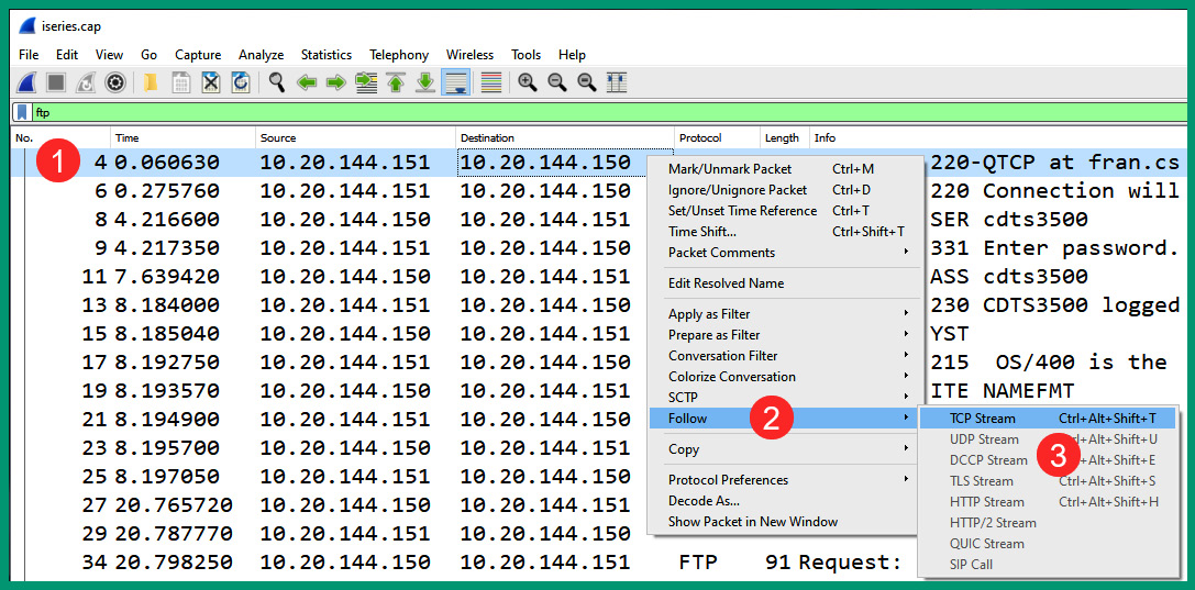
Figure 6.45 – Following the TCP stream
- Next, Wireshark will reassemble all the packets that are part of the TCP stream and open a new window displaying the entire transaction of messages between the client and server:
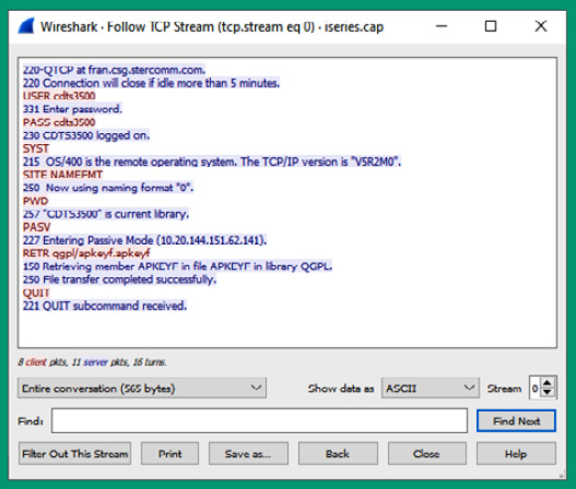
Figure 6.46 – TCP stream of packets
As shown in the preceding screenshot, the messages from the server to the client are displayed in blue, while the messages from the client to the server are displayed in red. You can see the username and password that were used to access the server and the commands entered by the user on the client device.
Having completed this lab, you have discovered the various fields and values that are found within FTP messages. In the next hands-on exercise, you will explore the difference between FTP and TFTP messages.
Lab – analyzing TFTP packets
In this hands-on lab, you will explore how TFTP packets learn to reconstruct data and extract files from captured TFTP packets on a network. To get started with this exercise, follow these steps:
- Go to https://wiki.wireshark.org/SampleCaptures and download the tftp_rrq.pcap file, as shown here:
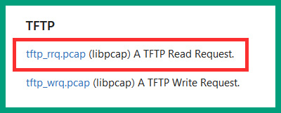
Figure 6.47 – TFTP packet capture file
- Next, open the tftp_rrq.pcap file using Wireshark to view all the packets:

Figure 6.48 – TFTP packets
As shown in the preceding screenshot, packet #1 is a Read Request message from the client to the TFTP server on the network and it’s requesting the rfc1350.txt file. Next, the file is transferred in multiple data blocks from the server at 192.168.0.10 to the client at 192.168.0.253 over the network.
- Within a total of 99 packets, the entire text file is transferred from the server to the client. To view the entire rfc1350.txt file, select File | Export Objects | TFTP, as shown here:
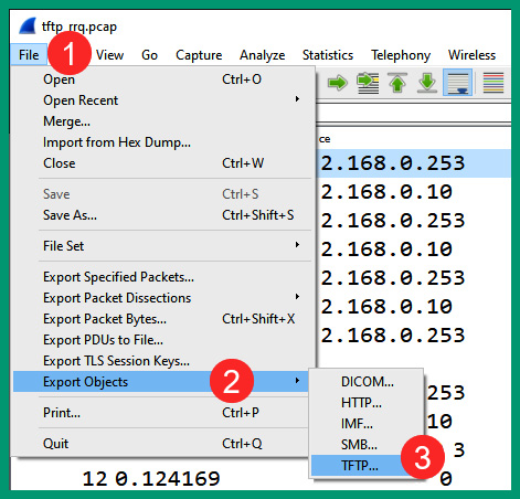
Figure 6.49 – Export menu
- Next, the Export Object window will appear and display the files that were found within the entire capture file, as well as the packet number that’s associated with finding the file. To extract the file from the packet capture, select the file and click on Save, as shown here:
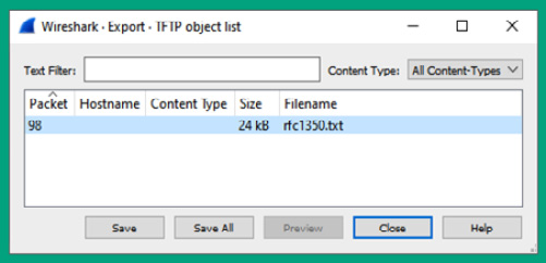
Figure 6.50 – Exporting a file
- Once you’ve exported the text file, open it with a text editor such as Notepad to view its contents:
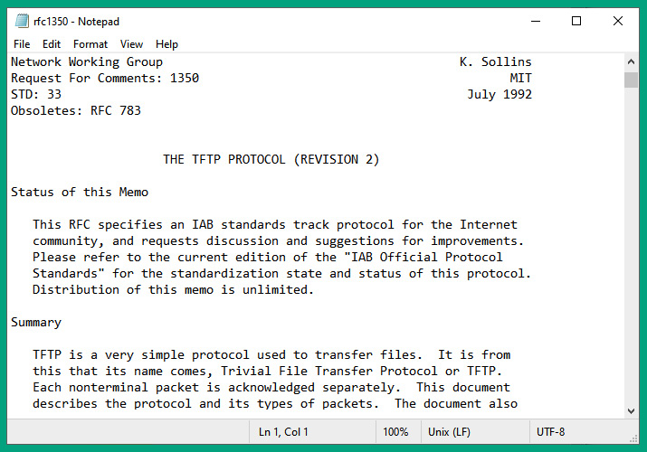
Figure 6.51 – Viewing the exported file
Having completed this exercise, you have learned how to analyze TFTP packets using Wireshark and extract the files that are transferred between a client and a server. In the next lab, you will explore captured SMB packets.
Lab – analyzing SMB packets
In this hands-on exercise, you will explore the security risks and discover how data is exchanged over a network between hosts that uses the SMB protocol. To get started with this exercise, follow these steps:
- First, go to https://www.7-zip.org/ to download the 7-Zip application and install it on your computer, as shown here:
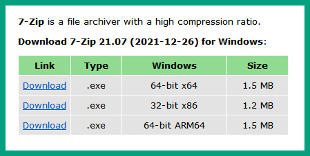
Figure 6.52 – 7-Zip application
- Next, go to https://wiki.wireshark.org/SampleCaptures and download the smbtorture.cap.gz file onto your computer, as shown in the following screenshot:
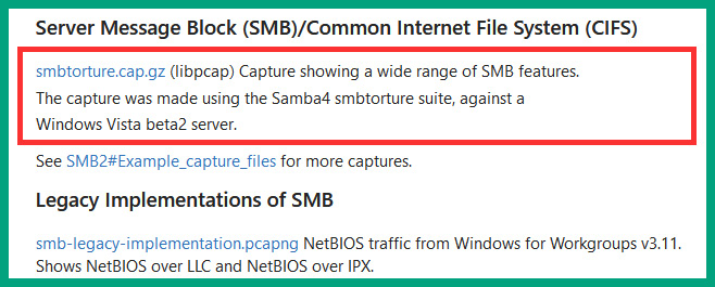
Figure 6.53 – SMB sample capture file
- Next, use the 7-Zip application to unzip/extract the smbtorture Wireshark capture file.
- Open the extracted smbtorture file using the Wireshark application, as shown here:
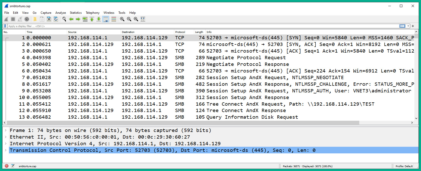
Figure 6.54 – SMB packets
As shown in the preceding screenshot, a client with an IP address of 192.168.114.1 is establishing an SMB connection to a server with an IP address of 192.168.114.129. Wireshark shows some details about the TCP 3-way handshake, the user credentials, and the directories that were accessed by the user.
- Next, select packet #9 and expand the SMB (Server Message Block Protocol) field within the Packet Details pane on Wireshark:
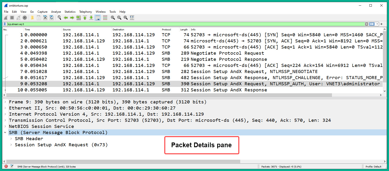
Figure 6.55 – SMB header
- Next, expand Session Setup AndX Request | Security Blob | GSS-API Generic Security Service Application Program Interface | Simple Protected Negotiation | negTokenTrag | NTLM Secure Service Provider. Here, you will see the username, NTLM hash, hostname of the client, and domain name that was used to request access to the SMB server:
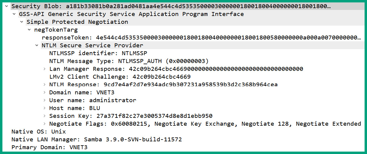
Figure 6.56 – SMB Request message
As shown in the preceding screenshot, the client sent all the information the SMB server needs to validate the identity and authenticity of the client before providing access to the shared network resources on the server.
- Next, select packet #11 to view the path (directory) that’s being requested by the client on the server:
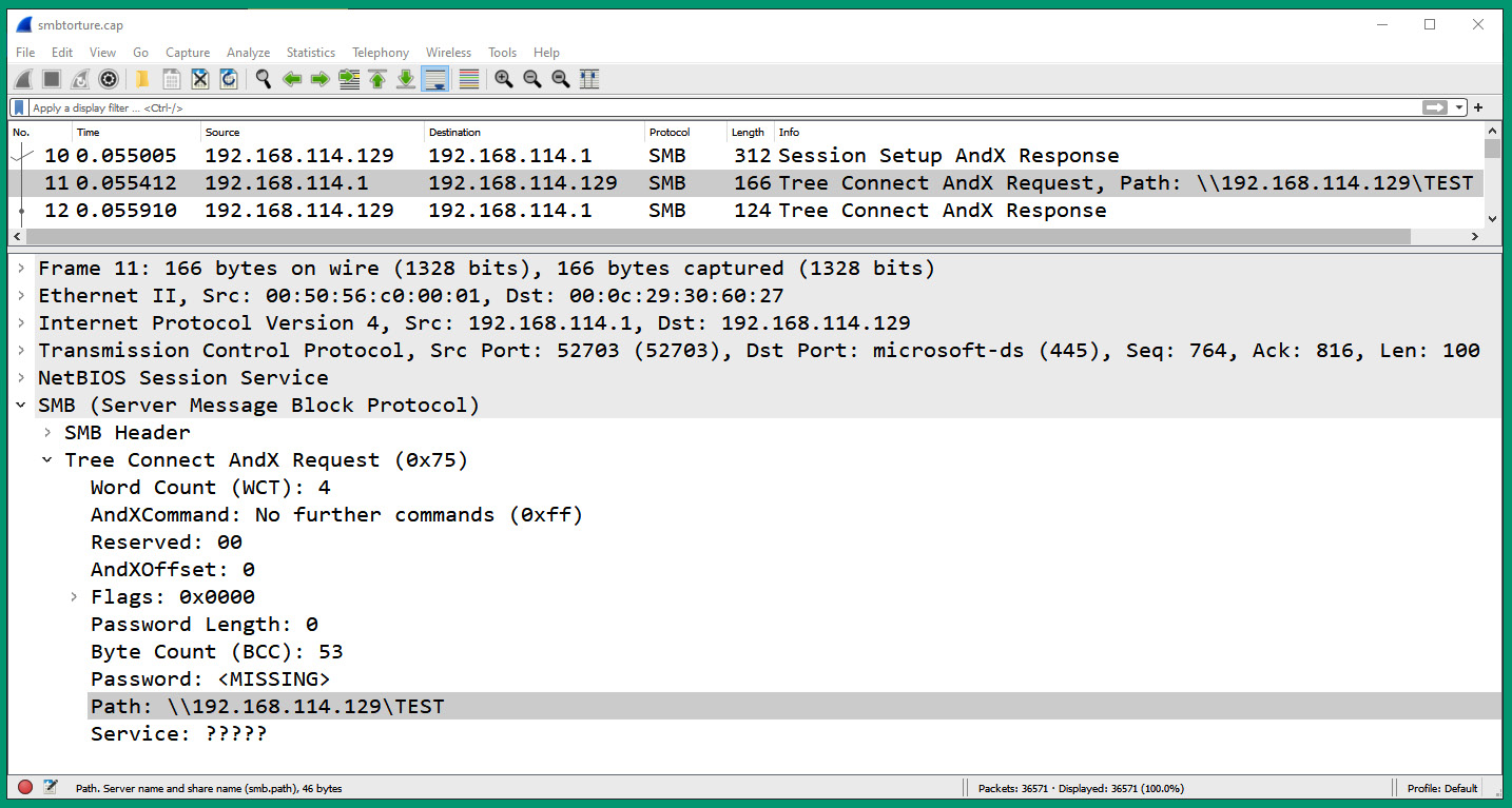
Figure 6.57 – SMB directory
As shown in the preceding screenshot, the client is requesting access to the \192.168.114.129TEST directory on the SMB server.
- Next, scroll through the remaining packets within the capture file and try to identify what the user is doing on the SMB server on the network. Some packets’ information will reveal the user is creating, modifying, and even deleting some of the files on the server.
- Next, to view all the files that were transmitted between the client and server, on Wireshark, select File | Export Objects | SMB, as shown here:
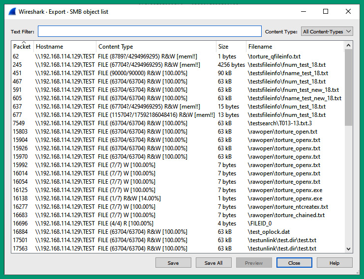
Figure 6.58 – SMB file transfers
As shown in the preceding screenshot, Wireshark was able to reassemble all the files that were exchanged using the SMB protocol between the client and server. You can choose to extract one or more files by using the Save and Save All buttons on the Export window.
- Lastly, when you’re finished working with Wireshark and analyzing the packets, you can close the application and document your findings as it will help you gain a better understanding of how communication occurs over a network.
Having completed this hands-on exercise, you have explored the SMB protocol using Wireshark, a protocol analyzer that provides you with the details found within each packet on a network.
Lab – analyzing Telnet packets
In this hands-on exercise, you will explore the security vulnerabilities of the Telnet protocol, as well as how a hacker can reassemble the data within each packet and view the entire conversation between a Telnet client and server over a network. To get started with this exercise, follow these steps:
- Go to https://wiki.wireshark.org/SampleCaptures and download the telnet-cooked.pcap file, as shown here:
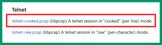
Figure 6.59 – Telnet capture file
- Next, open the telnet-cooked.pcap file using Wireshark to view all the captured packets:
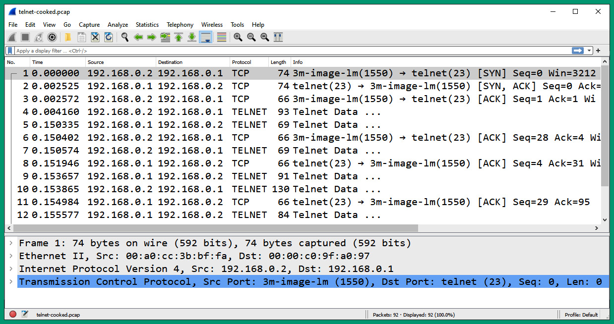
Figure 6.60 – Telnet packets
As shown in the preceding screenshot, there’s a client with an IP address of 192.168.0.2 that is establishing a Telnet session to a server with an IP address of 192.168.0.1.
- Next, right-click on packet #1 and select Follow | TCP Stream to view the entire conversation between the client and the Telnet server on the network:
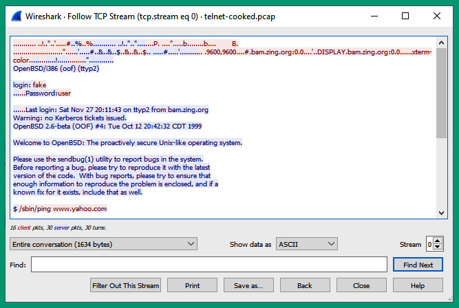
Figure 6.61 – Telnet conversation
As shown in the preceding screenshot, Wireshark was able to reconstruct the entire conversation that occurred between the client and server that were using the Telnet protocol. The message written in red is sent from the client to the server, while the messages written in blue are those from the server to the client. As mentioned previously, Telnet is an unsecure protocol that does not encrypt the messages between devices over a network. As a result, a threat actor such as a hacker can intercept the messages on a network and capture any sensitive and confidential information, as you have seen in this exercise.
Having completed this exercise, you have learned how a threat actor can view the information found within unsecure network protocols and have understood why it’s important to always use secure protocol whenever possible. In the next lab, you will learn how to listen to a VoIP call using Wireshark.
Lab – reassembling a SIP telephone conversation
In this hands-on lab, you will discover the security flaws found within the SIP protocol and how to assemble all the SIP packets and listen to a VoIP conversation that occurred over a network. To get started with this hands-on exercise, follow these steps:
- Go to https://wiki.wireshark.org/SampleCaptures and download the MagicJack+ short test call file:
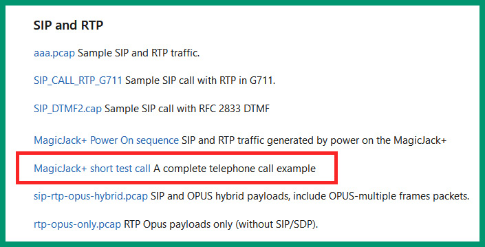
Figure 6.62 – Downloading the sample file
- Next, open the MagicJack+ short test call sample file using Wireshark to view all the captured packets:
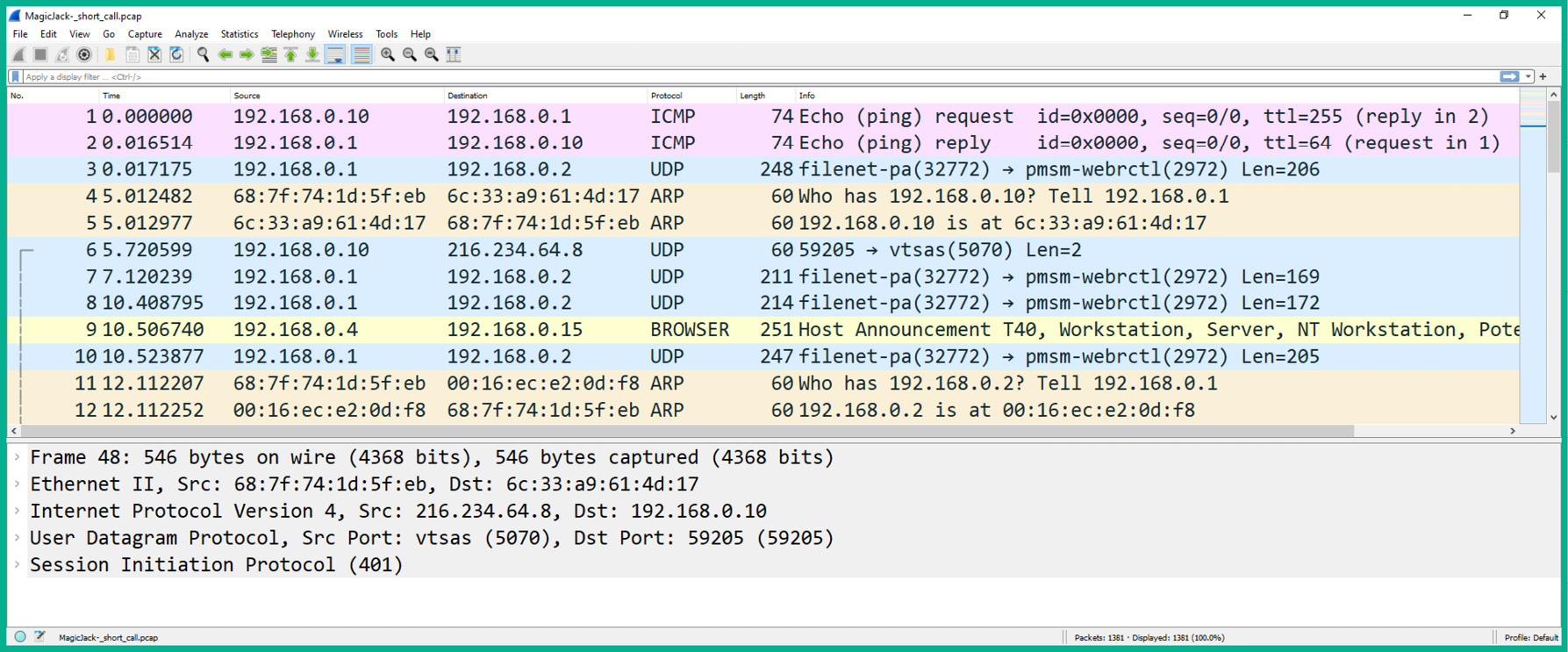
Figure 6.63 – SIP packet capture
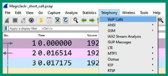
Figure 6.64 – Telephony menu
- Next, the VoIP Calls window will appear and display all the VoIP conversations that were found within the packet capture. You may need to press Prepare Filter before clicking on Play Streams to listen to the SIP call:
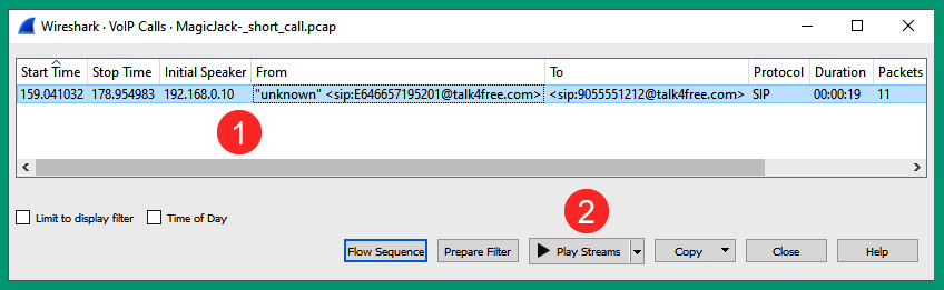
Figure 6.65 – VoIP calls
- Next, Wireshark will reassemble all the data found in the SIP packets and create an audio playback. Simply click the Play icon to play the audio:
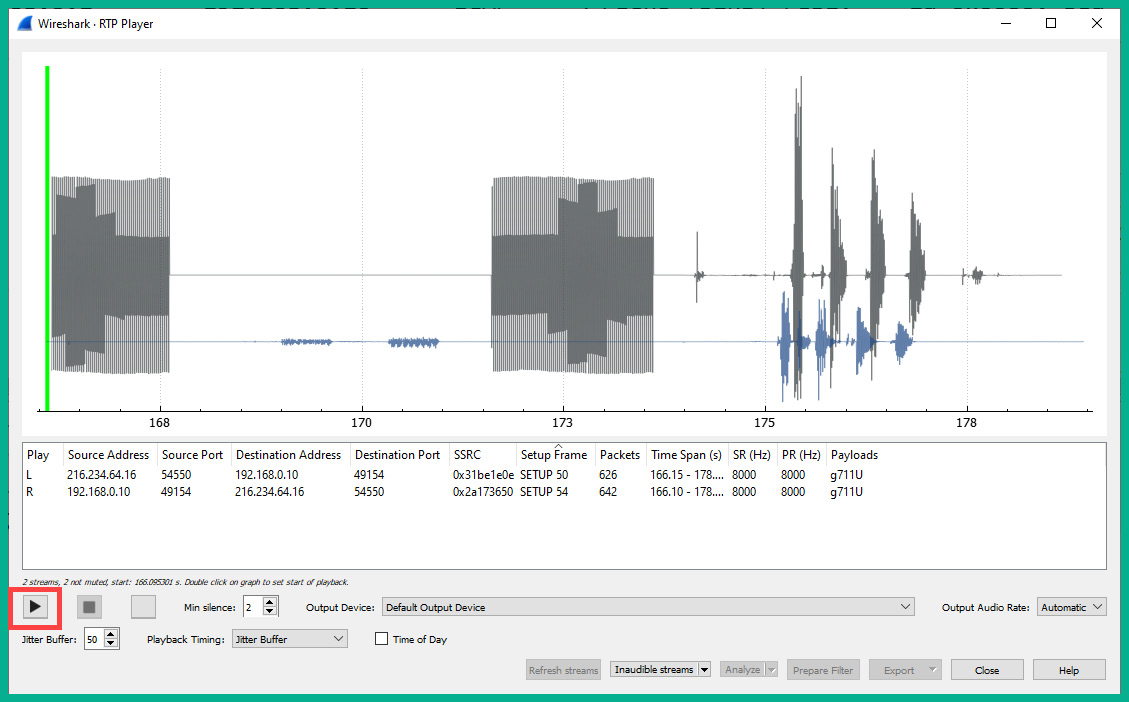
Figure 6.66 – Playing audio
Having completed this hands-on lab, you have gained the skills to identify VoIP calls using Wireshark and even listen to the audio found within the packets.
Summary
In this chapter, you learned about the roles and functions of common networking protocols and how they are used to format and exchange messages between hosts on a network. Additionally, you discovered various remote access protocols, such as Telnet, SSH, and RDP, as well as their security features. Furthermore, you discovered email protocols, database protocols, web protocols, directory protocols, and even VoIP protocols on networks.
As an aspiring network professional, you have gained the hands-on skills to perform packet analysis on various network protocols such as FTP, TFTP, Telnet, and SIP while observing how each protocol sends and receives data between devices. Lastly, you explored common network services that are needed within many organizations to ensure devices can communicate with other hosts on the network.
I hope this chapter has been informative for you and is helpful in your journey toward learning networking and becoming a network professional. In the next chapter, Chapter 7, Data Center Architecture and Cloud Computing, you will learn about the fundamentals of various data center architectures and cloud computing technologies and design models.
Questions
The following is a short list of review questions to help reinforce your learning and help you identify areas that may require some improvement:
- Which of the following protocols is used to download emails from an email server on a network?
A. SMTP
B. POP
C. IMAP
D. All of the above
- A network administrator is connected remotely to a router on the network. However, a hacker was able to capture the username and password used by the network administrator to log into the device. Which of the following protocols was most likely being used by the network administrator?
A. RDP
B. SSH
C. HTTP
D. Telnet
- A network administrator wants to securely upload files to a device over a network. However, the network administrator was able to connect to port 22 on the destination host. Which of the following protocols is being used by the network administrator?
A. FTPS
B. SSH
C. SFTP
D. HTTPS
- A network administrator is configuring an email server to securely send emails to their destinations. Which of the following protocols should be used?
A. SMTPS
B. DNS
C. SMTP
D. SSMTP
- Which of the following transport protocols does not guarantee that messages are sent over a network?
A. SIP
B. TCP
C. IP
D. UDP
- A network administrator wants to monitor the performance of all networking devices within their organization. Which of the following protocols will most likely allow the network administrator to retrieve the status information of a device?
A. SNMP
B. NTP
C. DHCP
D. RDP
- A network administrator wants to secure the communication between a directory server and clients on the network. Which of the following protocols is most suitable for this task?
A. LSDAP
B. LDAPS
C. SLDAP
D. LDAP
- Which of the following messages is sent to a DHCP server to confirm the use of an IP address?
A. Discover
B. Acknowledgment
C. Offer
D. Request
- Which of the following tools allows a network administrator to test connectivity between hosts on a network?
A. Traceroute
B. ICMP
C. Ping
D. Telnet
- A network administrator wants to forward log messages from all networking devices to a centralized logging server. Which of the following is the default service port for Syslog?
A. 154
B. 541
C. 514
D. 415
Further reading
To learn more about the topics that were covered in this chapter, check out the following links:
- What Is a Network Protocol, and How Does It Work?: https://www.comptia.org/content/guides/what-is-a-network-protocol
- What is the difference between authoritative and recursive DNS nameservers?: https://umbrella.cisco.com/blog/what-is-the-difference-between-authoritative-and-recursive-dns-nameservers