
Each modulation has a suitable demodulation scheme and we will focus on the ring and amplitude modulations in this section. The demodulator for the ring modulator uses exactly the same scheme as the modulator, so no new effect is to be expected there. The demodulator for the amplitude modulator is called an amplitude follower in the realm of digital audio effects. Several implementation schemes are available, some are inspired from analog designs, some are much easier to realize using digital techniques. These demodulators comprise three parts: a detector, an averager and a scaler.
3.3.1 Detectors
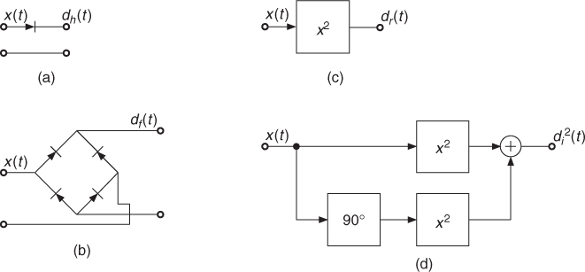
The detector can be a half-wave rectifier dh(t), a full-wave rectifier df(t), a squarer dr(t) or an instantaneous envelope detector ![]() . The first two detectors are directly inspired by analog designs. They are still useful to achieve effects having typical analog behavior. The third and fourth types are much easier to realize in the digital domain (Figure 3.9). The four detectors are computed by
. The first two detectors are directly inspired by analog designs. They are still useful to achieve effects having typical analog behavior. The third and fourth types are much easier to realize in the digital domain (Figure 3.9). The four detectors are computed by
3.17 ![]()
respectively, where x(n) denotes the input signal and ![]() its Hilbert transform.
its Hilbert transform.
Figure 3.9 Detectors: (a) half-wave, (b) full-wave, (c) squarer, (d) instantaneous envelope.
3.3.2 Averagers
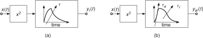
In the analog domain, the averager is realized with a resistor-capacitor (RC) network and in the digital domain using a first-order lowpass filter. Both structures are characterized by a time constant τ. The filter is implemented as:
3.18 ![]()
where d(n) denotes the detector output. The time constant τ must be chosen in accordance with the application. A short time constant is suitable when fast variations of the input signal must be followed. A larger time constant is better to measure the long-term amplitude of the input signal. For many applications, however, this averager is not suitable. It is often necessary to follow short attacks of the input signal. This calls for a very small time constant, 5 ms typically. The output of the averager will then react very fast to any amplitude variation, even to the intrinsic variations within a period of a low-frequency signal. We understand that we need an averager with two time constants: an attack time constant τa and a release time constant τr. To distinguish it from the basic averager, we will call this one the AR-averager. McNally has proposed an implementation having two fixed coefficients [McN84, Zöl05] and Jean-Marc Jot has an alternative where a single coefficient is varied according to the relationship between the input and the output of the averager (Figure 3.10):
3.19 
where d(n) again denotes the detector output.
Figure 3.10 RMS (root mean square) detectors. (a) single time constant; (b) attack and release time constants.
3.3.3 Amplitude Scalers
The systems described above lead to slightly different outputs. In order to get measures that are comparable with each other, it would be necessary to scale the outputs. Although scaling schemes are typically defined for sine waves, each type of signal would require a different scaling scheme. To build a RMS detector or an instantaneous envelope detector, furthermore a root extractor would be necessary, a computationally intensive operation. Fortunately, it is often possible to avoid the root extraction by modifying the circuit that makes use of the averager output, so that it works fine with squared measures. For these practical reasons the scaling is taken into account most of the time within the device that follows the averager output.
3.3.4 Typical Applications
Well-known devices or typical applications relate to the previous schemes as follows:
- The AM-detector comprises the half-wave rectifier and the basic averager.
- The volume meter (VU-meter) is an AM-detector. It measures the average amplitude of the audio signal.
- The peak-program-meter (PPM) is, according to DIN45406, a full-wave rectifier followed by an AR-averager with 10 ms attack time and 1500 ms release time.
- The RMS detector, as found in electronic voltmeters, uses the squarer and the basic averager.
- A sound-level-meter uses a RMS detector along with an AR-averager to measure impulsive signals.
- The RMS detector associated with an AR-averager is the best choice for amplitude follower applications in vocoders, computer music and live electronics [Dut98b, m-Fur93].
- Dynamics processors (see Section 4.2) use various types of the above-mentioned schemes in relation to the effect and to the quality that has to be achieved.
- The instantaneous envelope detector, without averager, is useful to follow the amplitude of a signal with the finest resolution. The output contains typically audio band signals. A particular application of the
 detector is the amplification of difference tones [Dut96, m-MBa95].
 - Otherwise static audio effects can be made more natural and lively by controlling certain parameters by characteristics of the input signal. One of these characteristics is the temporal envelope, which is, for example, used in the auto-wah or touch-wah effects, where the center frequency of a peak filter is controlled by the envelope of the input signal, see Section 2.4.1.