
9.3 Mapping Sound Features to Control Parameters
9.3.1 The Mapping Structure
While recent studies define specific strategies of mapping for gestural control of sound synthesizers [Wan02] or audio effects [WD00], some mapping strategies for ADAFX were specifically derived from the three-layer mapping that uses a perceptive layer [ACKV02, AV03, VWD06], which is shown in Figure 9.30. To convert sound features fi(n), i = 1, ..., M into effect control parameters cj(n), j = 1, ..., N, we use an M-to-N explicit mapping scheme3 divided into two stages: sound-feature combination and control-signal conditioning (see Figure 9.30).
Figure 9.30 Mapping structure between sound features and one effect control ci(n): sound features are first combined, and then conditioned in order to provide a valid control to the effect. Figure reprinted with IEEE permission from [VZA06].
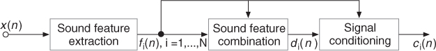
The sound features may often vary rapidly and with a constant sampling rate (synchronous data), whereas the gestural controls used in sound synthesis vary less frequently and sometimes in an asynchronous mode. For that reason, we chose sound features for direct control of the effect and optional gestural control for modifications of the mapping between sound features and effect control parameters [VWD06], thus providing navigation by interpolation between presets.
Defining a clear mapping structure offers a higher level of control and generalizes any effect: with adaptive control (remove the gestural control level), with gestural control (remove the adaptive control), or with both controls. Sound features are either short-term or long-term features; therefore they may have different and well-identified roles in the proposed mapping structure. Short-term features (e.g., energy, instantaneous pitch or loudness, voiciness, spectral centroid) provide a continuous adaptive control with a high rate that we consider equivalent to a modification gesture [Cad99] and useful as inputs (left horizontal arrows in Figures 9.31 and 9.32). Long-term features computed after signal segmentation (e.g., vibrato, roughness, duration, note pitch, or loudness) are often used for content-based transformations [ABL+03]. They provide a sequential adaptive control with a low rate that we consider equivalent to a selection gesture, and that is useful for control of the mapping (upper vertical arrows in Figures 9.31 and 9.32).
Figure 9.31 Feature combination, first stage of the sound-feature mapping. fi(n), i = 1, ..., M are the sound features, and dj(n), j = 1, ..., N are the combined features. Figure reprinted with IEEE permission from [VZA06].
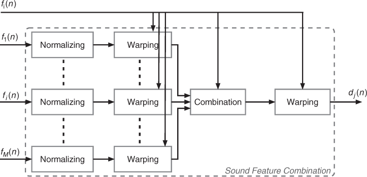
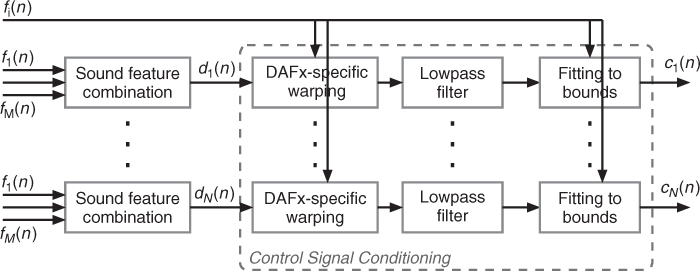
Figure 9.32 Signal conditioning, the second stage of the sound feature mapping. ci(n), n = 1, ..., N are the effect controls derived from sound features fi(n), i = 1, ..., M. The DAFx-specific warping and the fitting to boundaries can be controlled by other sound features. Figure reprinted with IEEE permission from [VZA06].
9.3.2 Sound-feature Combination
The first stage combines several features, as depicted in Figure 9.31. First, all the features are normalized in [0, 1] for unsigned values features and in [−1, 1] for signed value features. Second, a warping function—a transfer function that is not necessarily linear—can then be applied: a truncation of the feature in order to select an interesting part, low pass filtering, a scale change (from linear to exponential or logarithmic), or any non-linear transfer function. Parameters of the warping function can also be derived from sound features (for example the truncation boundaries). Third, the feature combination is done by linear combination, except when weightings are derived from other sound features. Fourth and finally, a warping function can also be applied to the feature combination output in order to symmetrically provide modifications of features before and after combination.
9.3.3 Control-signal Conditioning
Conditioning a signal consists of modifying the signal so that its behavior fits to pre-requisites in terms of boundaries and variation type. It is usually used to protect hardware from an input signal. The second mapping stage conditions the effect control signal di(n) coming out from the feature combination box, as shown in Figure 9.32, so that it fits the required behavior of the effect controls. It uses three steps: an effect-specific warping, a low pass filter and scaling. First, the specific warping is effect dependent. It may consist of quantizing the pitch curve to the tempered scale (auto-tune effect), quantizing the control curve of the delay time (adaptive granular delay, cf. Section 9.4.6), or modifying a time-warping ratio varying with time in order to preserve the signal length (cf. Section 9.4.2). Second, the low pass filter ensures the suitability of the control signal for the selected application. Third and last, the control signal is scaled to the effect control boundaries given by the user, that are eventually adaptively controlled. When necessary, the control signal, sampled at the block rate is resampled to the audio sampling rate fS.