
3.2.1 Ring Modulator
In the ring modulation (RM), the audio signal x(n) is multiplied by a sinusoid m(n) with carrier frequency fc, as in Figure 3.1. While difficult in the analog domain, the multiplication is straightforward to realize in the digital domain [Ste87]. The input signal is called the modulator x(n) and the second operand is called the carrier m(n), giving the output signal
3.1 ![]()
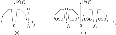
If m(n) is a sine wave of frequency fc, the spectrum of the output y(n) is made up of two copies of the input spectrum: the lower side band (LSB) and the upper side band (USB). The LSB is reversed in frequency and both side band are centered around fc (see Figure 3.2). Depending on the width of the spectrum of x(n) and on the carrier frequency, the side bands can be partly mirrored around the origin of the frequency axis. If the carrier signal comprises several spectral components, the same effect happens with each component. Although the audible result of a ring modulation is fairly easy to comprehend for elementary signals, it gets very complicated with signals having numerous partials. The carrier itself is not audible in this kind of modulation. When carrier and modulator are sine waves of frequencies fc and fx, one hears the sum and the difference frequencies fc + fx and fc − fx [Hal95].
Figure 3.1 Ring modulation of a signal x(n) by a sinusoidal carrier signal m(n).
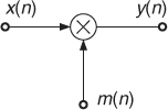
Figure 3.2 Ring modulation of a signal x(n) by a sinusoidal carrier signal m(n). The spectrum of the modulator x(n) (a) is shifted to the carrier frequency (b).
When the input signal is periodic with fundamental frequency f0, a sinusoidal carrier of frequency fc produces a spectrum with amplitude lines at the frequencies |kf0 ± fc| [DP00]. A musical application of this effect is applied in the piece “Ofanim” by Luciano Berio. The first section is dominated by a duet between a child voice and a clarinet. The transformation of the child voice into a clarinet is desired. For this purpose a pitch detector computes the instantaneous frequency f0(n) of the voice. Then the child voice passes through a ring modulator, where the frequency of the carrier fc is set to f0(n)/2. This emphasizes odd harmonics, which is similar to the sound of a clarinet in the low register [Vid91].
3.2.2 Amplitude Modulator
The amplitude modulation (AM) was easier to realize with analog electronic means than the ring modulation and has therefore been in use for a much longer time. It can be implemented by
3.2 ![]()
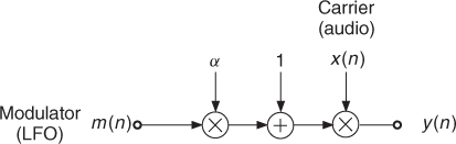
where it is assumed that the peak amplitude of m(n) is 1. The coefficient α determines the modulation depth. The modulation effect is maximum when α = 1 and the effect is disengaged when α = 0. A typical application is with an audio signal as carrier x(n) and a low-frequency oscillator (LFO) as modulator m(n) (see Figure 3.3). The amplitude of the audio signal varies according to the instantaneous amplitude value of the LFO.
Figure 3.3 Typical application of AM.
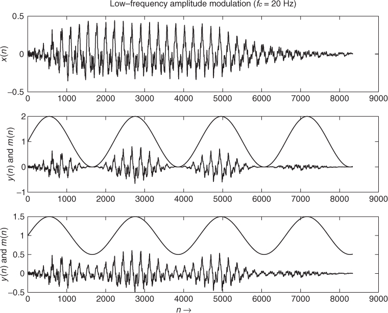
When the modulator is an audible signal and the carrier a sine wave of frequency fc, the spectrum of the output y(t) is similar to that of the ring modulator except that the carrier frequency can be also heard. When carrier and modulator are sine waves of frequencies fc and fx, one hears three components: carrier, difference and sum frequencies (fc − fx, fc, fc + fx). The effect is perceived in a different manner depending on the frequency range of the signals. A modulation with frequencies below 20 Hz will be heard in the time domain (variation of the amplitude, tremolo in Figure 3.4), whereas modulations by medium frequencies (20–70 Hz) introduce auditory roughness into the signal. Modulations by high frequencies will be heard as distinct spectral components (LSB, carrier, USB).
Figure 3.4 Tremolo effect by AM.
3.2.3 Single-side-band Modulator
The upper and lower side bands of RM and AM carry the same information, although organized differently. In order to save bandwidth and transmitter power, radio-communication engineers have designed the single-side band (SSB) modulation scheme (Figure 3.5). Either the LSB or the USB is transmitted. Phase shifted versions by 90° of the modulating audio signal x(n) are denoted by ![]() and of the carrier signal m(n) by
and of the carrier signal m(n) by ![]() , and are produced by Hilbert transform filters [Orf96]. The upper and lower side-band signals can be computed as follows:
, and are produced by Hilbert transform filters [Orf96]. The upper and lower side-band signals can be computed as follows:
3.3 ![]()
3.4 ![]()
A discrete-time Hilbert transform can be approximated by a FIR filter with the impulse response
3.5 
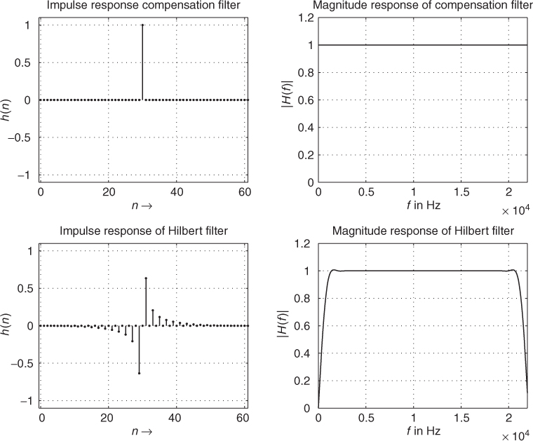
After truncation to the desired length N, these coefficients are multiplied with a suitable window function, for example a Hamming window, and shifted right by ![]() to make the filter causal. Note that the use of the FIR Hilbert filter requires a delay in the direct path for the audio and the carrier signal. Figure 3.6 shows an example with the compensation delay of 30 samples and a FIR Hilbert filter of length N = 61. This effect is typically used with a sine wave as carrier of frequency fc. The use of a complex oscillator for m(n) simplifies the implementation. By using positive or negative frequencies it is then possible to select the USB or the LSB. The spectrum of x(n) is frequency-shifted up or down according to fc. The results are detune effects and non-harmonic sounds: a piano tone may sound like a bell after processing or a plucked-string sound is heard like a drum sound. The modification in perceived pitch is much less than expected, probably because our ear recovers pitch height and salience information also from cues other than the absolute frequency of the lowest partial (“fundamental”) present in the actual tone [Dut91], the most prominent of which being the frequency difference between the different partials (“overtones”). These effects are explained and modeled by, for example, the theory of “virtual pitch” [TSS82a, TSS82b]. A review of legacy frequency-shifters can be found in [Bod84].
to make the filter causal. Note that the use of the FIR Hilbert filter requires a delay in the direct path for the audio and the carrier signal. Figure 3.6 shows an example with the compensation delay of 30 samples and a FIR Hilbert filter of length N = 61. This effect is typically used with a sine wave as carrier of frequency fc. The use of a complex oscillator for m(n) simplifies the implementation. By using positive or negative frequencies it is then possible to select the USB or the LSB. The spectrum of x(n) is frequency-shifted up or down according to fc. The results are detune effects and non-harmonic sounds: a piano tone may sound like a bell after processing or a plucked-string sound is heard like a drum sound. The modification in perceived pitch is much less than expected, probably because our ear recovers pitch height and salience information also from cues other than the absolute frequency of the lowest partial (“fundamental”) present in the actual tone [Dut91], the most prominent of which being the frequency difference between the different partials (“overtones”). These effects are explained and modeled by, for example, the theory of “virtual pitch” [TSS82a, TSS82b]. A review of legacy frequency-shifters can be found in [Bod84].
Figure 3.5 Single-side-band modulator with compensation filter CF and Hilbert filter (90° block).
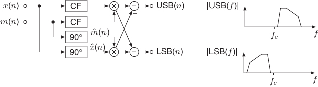
Figure 3.6 Delay compensation and Hilbert filter.
3.2.4 Frequency and Phase Modulator
The frequency modulation (FM) is widely used for broadcasting and has found interesting applications for sound synthesis [Roa96]. The continuous-time description of an angle-modulated carrier signal is given by
3.6 ![]()
where Ac is the amplitude of the signal and the argument of the cosine is given by the carrier frequency fc and the modulating signal m(t) according to
3.7 ![]()
3.8 ![]()
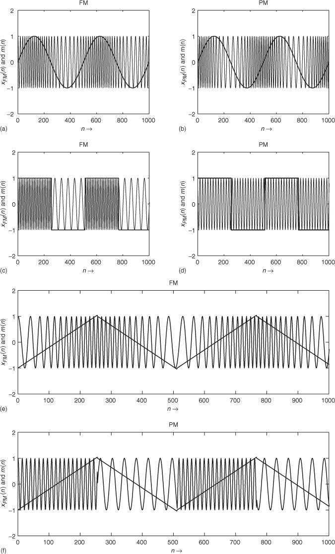
For phase modulation (PM) the phase ϕ(t) is directly proportional to the modulating signal m(t), while for frequency modulation the phase ϕ(t) is the integral of the modulating signal m(t). Some examples of frequency and phase modulation are shown in Figure 3.7. In the first example the modulating signal is a sinusoid which shows that the resulting FM and PM signals are the same except for a time shift in the modulation characteristic. The second example in (c) and (d) depicts the difference between FM and PM, where the modulating signal is now a bipolar pulse signal. The last example in (e) and (f) depicts the result of a ramp type signal. The main idea behind using these techniques is the control of the carrier frequency by a modulating signal m(n).
Figure 3.7 Examples of angle modulation.
Applying phase modulation to audio signals for audio effects is different from the previous discussion, where a modulating signal m(n) is used to modify the phase ϕ(t) of a cosine of fixed carrier frequency fc. By contrast, for audio effects the phase of the audio signal x(n) is modified by a control parameter or modulating signal m(n). The phase modulator system can be described by a time-variant impulse response h(n) and leads to a phase modulated output signal xPM(n) according to
3.9 ![]()
3.10 ![]()
The result for phase modulation (PM) of the signal x(n) can then be written as
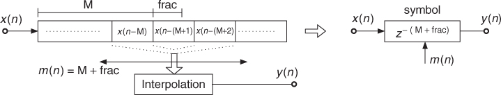
where m(n) is a continuous variable, which changes every discrete time instant n. Therefore m(n) is decomposed into an integer and a fractional part [Dat97]. The integer part is implemented by a series of M unit delays, the fractional part is approximated by interpolation filters, e.g., linear, Lagrange, allpass [Dat97, LVKL96, Zöl05] or spline filters [Dis99] (see Figure 3.8 and Section 2.5.4). The discrete-time Fourier transform of (3.11) yields
3.12 ![]()
which expresses the phase modulation of the input signal by a time-variant delay m(n).
Figure 3.8 Phase modulation by delay-line modulation.
For sine-type modulation, useful for vibrato effects, the modulation signal can be written as
3.13 ![]()
For a sinusoidal input signal the so-called resampling factor for sine-type modulation can be derived as
3.14 ![]()
The instantaneous frequency is denoted by fI and the frequency of the input sinusoid is denoted by f. The resampling factor is regarded as the pitch-change ratio in [Dat97]. For sine-type modulation the mean value of the resampling factor α(n) is one. The consequence is an output signal which has the same length as the input signal, but exhibits a pitch variation centered around the original pitch, implementing a vibrato effect.
For ramp-type modulation according to
3.15 ![]()
the resampling factor α(n) for the sinusoidal input signal is given by
3.16 ![]()
The output signal is pitch transposed by a factor α and the length of the output data is altered by the factor 1/α. This behavior is useful for pitch-transposing applications, as will be detailed in Section 6.4.3.