
Even a conductor (such as a metal wire) is not 100% efficient
at
conducting current flow. As current flows through the wire, energy
will be lost as heat (and sometimes light). For very small currents,
this energy loss is negligible, but for large currents, the loss can
cause the conductor to become quite hot (an effect utilized in
toasters) or glow brightly (lightbulbs). This loss of energy results
in a voltage difference across the wire (or component). The component
is said to resist the current flow. This
resistance (also known as
impedance, although impedance is somewhat more
complex than simple resistance) is measured in
Ohms (unit symbol Ω, equation symbol
R). Schematics commonly leave off the Ω symbol, so
100kΩ is usually written as just 100k.
Tip
On a schematic, a 4.7kΩ value may be written not as 4.7k, but rather as 4k7. The reason is that it is too easy for a decimal point to be missed or lost when the document is photocopied. The solution is to place the multiplier (k) in the position of the decimal point. Resistors such as 24.9Ω are written as 24R9.
This convention is used by design engineers in most of the world. However, in North America, it is only sometimes followed.
The relationship between voltage, current, and resistance is known as
Ohm's
Law
, and is given by:
V = I * R
For a fixed resistance, a varying voltage will produce a varying
current, while a constant voltage will produce a constant current.
Hence, a varying voltage source is known as an Alternating
Current source (or AC), while
a
constant voltage source is known as a Direct
Current source (DC). An AC voltage is
normally specified as VAC, while a DC voltage is
either VDC or more often just
V.
Tip
The stuff that comes out of your wall socket is AC and is nominally
110-120VAC (at 60Hz) if you live in North America, 100VAC if
you’re in Japan (50Hz in the eastern
half—Tokyo—and 60Hz in the western half—Osaka,
Kyoto, and Nagoya), and 220-240VAC (at 50Hz) if
you’re in Australia, New Zealand, the UK, or Europe.
All digital electronics, and that includes computers, use DC
internally and operate at typical voltages of either 5V or 3.3V.
(Some digital electronics will operate at voltages as low as 1.8V or
even lower.) The power supply of the computer
(or TV or stereo or . . . ) converts the high-voltage AC supply into
the lower DC required by the electronics. The AC adaptor or plug pack
(charger) for your cell phone is also an example of a power supply.
For a given voltage difference, the smaller the resistance, the
larger the current flow. Conversely, the bigger the resistance, the
smaller the current flow. In this way, resistance can be used to
limit the current flow through a particular part of a circuit.
Special components, known as resistors, are
produced for precisely this purpose. The schematic component symbols
for a resistor are shown in Figure 2-5. Both
symbols mean the same thing. The more commonly seen symbol is on the
left.
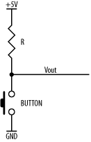
A resistor may be used to pull up (or
pull down) a signal line to a given voltage
level. Figure 2-6 shows a pull-up resistor and a
push button. When the button is open (not pressed), there is no
current flow through the resistor, therefore the voltage at
VOUT is (in this case) +5V. (Since there is no
current flow through the resistor, there is no voltage drop across
it.) When the button is pushed, VOUT is
connected to ground, and as a consequence, current will flow through
the resistor. This simple circuit can be used to switch an input
between two logic-level thresholds.
Resistors may be combined together to increase resistance. This is
known as
a
series
connection
(Figure 2-7).
The combined total resistance is given by the relation:
RTOTAL = R1 + R2
The current flow through any of the components
in series connection will be the same for each component. In other
words, the current flowing through the first resistor will be the
same as through the second resistor. This derives from
Kirchhoff's Current
Law
.
Note
Kirchhoff’s Current Law
The current flowing through a given circuit point is equal to the sum of the currents flowing into that circuit point and is also equal to the sum of currents flowing out of that circuit point.
In other words, what flows in must flow out.
Resistors may be used in
a
voltage divider (Figure 2-8),
to provide an intermediate voltage.

The output voltage is given by:
VOUT = VIN * R2 /(R1 + R2)
For example, if the input voltage is 5V, and the two resistors are both 1kΩ, then the output voltage is:
VOUT        = 5V * 1k /(1k + 1k)
            = 5V * 1k / 2k
            = 5V * 0.5
            = 2.5V
As you would expect, a voltage divider using equal resistors halves the input voltage.
Resistors combined in parallel (Figure 2-9) will decrease the total resistance.

The combined total resistance is given by the relation:
RTOTAL = 1 / (1/R1 + 1/R2)
The voltage drop across R1 must be the same as the voltage drop
across R2. However, unless R1 is equal to R2 (and there is no
requirement for them to be equal), the current flows through each
will be different. This is derived from
Kirchhoff's Voltage
Law
.
Resistors are part of a family of devices known
as
passive
components
. The other common passive component is
the
capacitor.