
Being an electronic circuit, the operation of a computer is about voltages and current flow. Understanding the basic principles of voltages and current flow within the computer is mandatory if you’re going to produce a working system. Common operating voltages inside a computer are normally either 5V or 3.3V. For some low-power or exceptionally fast computers, voltages may be as small as 1.8V or even lower.
An output pin of a digital device can be in one of three states. It
can be high (logic 1), low
(logic 0), or
tristate
(high
impedance
, also known as
floating
).
A logic high is defined as the output voltage at the pin being higher
than a given threshold. When a device’s pin is
outputting a high, it is said to be sourcing
current
to that connection. Similarly, a logic
low is when the output voltage is below a given threshold, and the
device’s pin is said to be sinking
current
. Typically,
components can sink more current than they can source.
A tristate pin is outputting neither a high nor a low. Instead, it becomes high impedance (high resistance) so that current flow in or out of the pin is negligible. It is, in effect, invisible to other components to which it is connected. For example, within a computer system may be several memory devices connected to the data bus. When a particular device is being read, its data outputs will be either high or low (corresponding to the bit pattern being read back). All other memory devices in the system, because they are not being accessed, will have their data buses tristate. They take no part in the read transaction between the processor and the accessed memory device.
The threshold for logic high and the threshold for logic low can vary
from device type to device type. For an input device to recognize a
given signal as high or low, the output device must provide that
signal within the appropriate limits. The thresholds can vary, but
are always consistent across devices of the same logic
families
. Back in the good old days, the number
of logic families was limited, and each device within a family
conformed to the thresholds of that family. Life, and designing
digital systems, was easier. Now, with the quest for
ever-lower-powered devices and the desire for devices to be as
versatile as possible, there is considerable diversity with the
thresholds for logic high and logic low. So the input low threshold
for a given chip may not match the output low threshold for the chip
to which it is connected. Therefore, it is vitally important to check
the datasheets of all the components you are using and ensure that
they will work together.
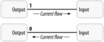
When a device outputs a logic high and its output voltage is greater than the high threshold for the input device, current will flow from the output pin to the input pin. The output device is sourcing current, while the input device is sinking current.
Conversely, for certain types of digital logic, when a device outputs a logic low and its output voltage is lower than the low threshold of the input device, current will flow from the input pin to the output pin, even though the output device is the one controlling the voltage. The output device is sinking current, while the input device is sourcing current (Figure 2-38).
The magnitude of the current flow is important. A given device will have limitations on how much current it can sink or source. Exceeding this current limit can permanently damage an integrated circuit. It is therefore important to calculate the current flows within your system and ensure that all the requirements are met.