
Through the late ’70s and ’80s, the complexity of automotive electronics had grown considerably, with engine management systems, ABS braking, active suspension, electronic transmissions, and automated lighting, air-conditioning, security, and central locking. These individual systems do not exist in isolation; each is part of an integrated whole. A considerable amount of information exchange is required, and therefore some means of system interconnection must be provided. The conventional method was for point-to-point wiring, providing discrete interconnection between each subsystem. This methodology was a natural evolution from the simple electrical systems of earlier cars, but as automotive complexity grew, such a scheme proved vastly inadequate. Each car could have several kilometers worth of wiring and dozens of connectors. Such complex wiring systems added greatly to the cost of producing a car, added unnecessary weight, reduced reliability, and made servicing a nightmare.
The obvious solution was to replace complexity with simplicity and implement intersystem communication using a low-cost digital network. The automotive electrical environment is very noisy. With electric motors, ignition systems, RF emissions, and so on, the 12V supply to automotive electronics can have ±400V transients. The required communication network must therefore be able to cope with this noise and work reliably. The network must provide high-noise immunity, as well as error detection and handling, with retransmission of failed packets. Thus was born the Controller Area Network, more commonly known as CAN, implementing real-time communication at up to 1Mbps over a two-wire serial network. CAN specifies only the physical and data-link layers of the ISO-OSI model, with higher layers being left to the specific implementation.
Bosch developed CAN in Europe in the late 1980s, originally for use in cars. Because of its robustness, CAN has expanded beyond its automotive origins and can now be found in industrial automation, trains, ship navigation and control systems, medical systems, photocopiers, agricultural machinery, household appliances, office automation, and elevators. CAN is now an international standard under ISO11898 and ISO11519-2.
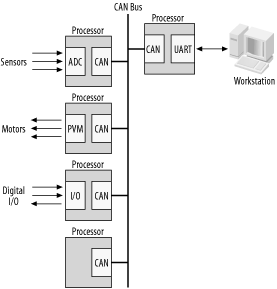
CAN supports multiple masters on the network, with each master responsible for local sensing and control within the distributed system (Figure 11-6).
Each CAN packet contains address information and priority as part of the header, and the nodes may connect to the network, or disconnect from the network, without affecting network traffic between other nodes.
The CAN network uses wired-AND logic, with a maximum bus length of 1000 meters (3300 feet) and a bus length of 40 meters (133 feet) at maximum data rate over twisted-pair wiring. Each end of the bus requires termination resistors to prevent transmission reflections (Figure 11-7).

Many processors intended for use in harsh or electrically noisy industrial applications include a CAN module. A number of Philips microcontrollers include CAN, as do a few PICs. The DSP56805 processor we covered in Chapter 8 also has a CAN interface. For processors that do not include CAN, CAN interface modules are available. The Microchip MCP2510 provides a CAN module that interfaces to a host processor via SPI. Adding CAN to any embedded system is therefore a simple task.
Typically, a microprocessor that supports CAN will include a CAN interface module, which provides most of the functionality. The only additional support required is a CAN interface driver (just as in RS485 and RS232C). Philips Semiconductor produces a CAN driver, the PCA82C250T, which makes interfacing to the CAN bus very easy.
Your embedded computer must also have some way of physically attaching to the bus. The simplest method is simply to bring the bus into the computer system on one connector, tap off it, and then route it out through another connector (Figure 11-8).

To see how we can use CAN, let’s look at the DSP56805 processor. This processor has a CAN network module as part of its suite of onboard peripherals. The schematic for interfacing a processor’s CAN module to a CAN bus is shown in Figure 11-9.

The DSP56805 has two CAN interface signals, MSCAN-TX and MSCAN-RX, the CAN transmitter and receiver, respectively. These are connected to the PCA82C250T, which provides the interface to the CAN bus. Note that the DSP56805 requires a 3.3V supply, while the PCA82C250T requires a 5V supply. A pull-up resistor brings the MSCAN-TX output of the processor to the required logic high level for the PCA82C250T. While CAN requires only two signal lines and ground, the actual connectors have eight pins. Since the CAN bus requires a termination resistor at each end, we provide a 120Ω resistor, should our computer be placed at the bus end. A jumper allows it to be brought in-circuit or disabled as needed. So, if our computer is at the end of the CAN bus, the jumper is closed and the bus is terminated. If our computer is not an end-point machine, the jumper is left open, and the resistor plays no part. Note that having a termination resistor active (jumper closed) when this computer is not at an end point is a good way to ensure an unreliable CAN bus! Resistors should be active at bus ends only.
Many implementations of CAN just use standard IDC-type headers for the connectors. However, the actual CAN standard specifies that the connector should be a nine-pin Sub-D connector. The pinouts for this connector are listed in Table 11-1.
Table 11-1. CAN pinouts
|
Pin |
Signal/Use |
|---|---|
|
1 |
Reserved |
|
2 |
CAN_L |
|
3 |
Ground |
|
4 |
Reserved |
|
5 |
Reserved |
|
6 |
Ground |
|
7 |
CAN_H |
|
8 |
Reserved |
|
9 |
V+ (optional power source) |
Although this is the same type of connector used in some RS-232C implementations (such as the serial ports on PCs), do not connect a CAN bus and RS-232C together. They are not even remotely compatible!