
For many simple digital applications, a small microprocessor is a better choice than discrete logic, for it is able to execute software. It is therefore able to perform certain tasks with much less hardware complexity. I’ll show you just how easy it is to produce a small, embedded computer for integration into a larger system, using an ATMEL ATtiny15 AVR processor. This processor has 512 words of flash for program storage and no RAM! (Think on that when next you have to install some 100-megabyte application on your desktop computer!) This tiny processor, unlike its bigger AVR siblings, relies solely on its 32 registers for working-variable storage.
Since there is no RAM in which to allocate stack space, the ATtiny15
instead uses a dedicated hardware stack that is a mere
three entries deep, and this is shared by
subroutine calls and interrupts. (That fourth nested function call is
a killer!) The program counter is 9-bits wide (addressing 512 words
of program space); therefore, the stack is also 9-bits wide. Also
unlike the bigger AVRs, only two of the registers
(r30 and r31) may be coupled as
a 16-bit index register (called Z).
The processor also has 64 bytes of EEPROM (for holding system parameters), up to five general-purpose I/O pins, eight internal and external interrupt sources, two 8-bit timer/counters, a four-channel 10-bit analog-to-digital converter, and an analog comparator and is able to be reprogrammed in-circuit. It comes in a tiny 8-pin package, out of which you can get up to 8 MIPS performance. We’re not going to worry about most of its features for the time being. That’ll all be covered in later chapters when we take a look at I/O. Instead, we’re just going to concentrate on how you use one for simple digital control.
Using a small microcontroller such as the ATtiny15 is very easy. The basic processor needs very little external support for its own operation. Figure 6-3 shows just how simple it is.

Let’s take a quick run-through of the design (what there is of it). VCC is the power supply. It can be as low as 2.7V or as high as 5.5V. VCC is decoupled to ground using a 0.1μF capacitor. The five pins, PB0 through PB4, can act as digital inputs or outputs. They could be used to read the state of switches, to turn external devices on or off, to generate waveforms to control small motors, or even to synthesize an interface to simple peripheral chips. The digital I/O lines, PB0 through PB4, get connected to whatever you’re using the processor to monitor or control. We’ll look at some examples of that later in the chapter.
Finally, one input, RESET , is left unconnected. On just about any other processor, this would be fatal. Many processors require an external power-on reset (POR) circuit to bring them to a known state and to commence the execution of software. Some processors have an internal power-on reset circuit and require no external support. Such processors still have a reset input, allowing them to be manually reset by a user or external system. Normally, the reset input still requires a pull-up resistor to hold it inactive. But the ATtiny15 processor doesn’t require this. It has an internal power-on reset and an internal pull-up resistor. So, unlike most (maybe all) other processors, RESET on the ATtiny15 may be left unconnected. In fact, on this particular processor, the RESET pin may be utilized as a general-purpose input (PB5) when an external reset circuit is not required. One important point: the normal input protection against higher than normal voltage inputs is not present on RESET/PB5 , since it may be raised to +12V during software download by the program burner. Therefore, you must take great care if using PB5 that the input never exceeds VCC by more than 1V. Failing to do so may place the processor into software-download mode, and thereby effectively crash your embedded computer.
The AVR processors (and PICs too) include an internal circuit known
as a brownout
detector
(BOD). This
detects minor fluctuations on the processor’s power
supply that may corrupt its operation, and if such a fluctuation is
detected, it generates a reset and restarts the processor. There is
also an additional reset generator, known
as a
watchdog, used to restart the computer in case
of a software crash. It is a small timer whose purpose is to
automatically reset the processor once it times out. Under normal
operation, the software regularly restarts the watchdog.
It’s a case of
“I’ll reset you, before you reset
me.” If the software crashes, the watchdog
isn’t cleared and so times out, resetting the
computer. Processors that incorporate watchdogs normally give
software the ability to distinguish between a power-on reset and a
watchdog reset. With a watchdog reset, it may be possible to recover
the system’s state from memory and resume operation
without complete reinitialization.
Now the other curious aspect of this design is that there is no clock circuit. The ATtiny15 can have an external crystal circuit. (On the ATtiny15, PB3 and PB4 function as the crystal inputs, XTAL1 and XTAL2.) But our design doesn’t have a crystal, or even need one. The reason is that this little processor includes a complete internal oscillator (in this case, an RC oscillator), running at a frequency of 1.6MHz, and so requires no external components for its clock. The catch is that RC oscillators are not that stable and have the tendency to vary their frequency as the temperature changes. (The ATtiny15’s oscillator can vary between 800kHz and 1.6MHz.) Generally, an RC oscillator is not really suitable for timing-critical applications (in which case, you’d use an external crystal instead). But if your ATtiny15 is just doing simple control functions, timing may not be an issue. You can therefore get by with using the internal RC oscillator and save on complexity. ATMEL provides an 8-bit calibration register (OSCCAL) in the ATtiny15 that enables you to tune the internal oscillator, thus making it more accurate.
There we have the basic design for an ATtiny15 machine. In essence, it’s a very cheap, small, and versatile computer that requires no work for the core design. The only design effort needed is to ensure that the computer will work correctly with the I/O devices to which it is interfaced. If you’re going to power the system off a battery, then the capacitor is optional as well! The only component that must be there is the processor itself. (And you thought designing computer hardware was going to be hard.)
That’s the basic AVR computer hardware, with minimal components. We’ll look at how you download software to it shortly.
So, that covers the basics of a ATtiny15 system, and it’s not that much different from the corresponding PIC12C508 computer. The real differences lie in their internal architectures (and instruction sets) and in the subtleties of their operating voltages and interfacing capabilities. As you can see, there’s not a lot of hard work involved in putting one of these little machines into your embedded system.
So far, neither of our computers is interfaced to anything. Let’s start with something simple, adding a LED to the AVR. The basic technique applies to all microcontrollers with programmable I/O lines, as well.
LEDs (Light-Emitting Diodes) produce light when current flows through them. Being diodes, they conduct only if the current is flowing in the right direction, from anode (positive) to cathode (negative). The cathode end of a LED is denoted on a schematic by the horizontal bar. The anode is the triangle.
The circuit for a status LED is shown in Figure 6-4. It uses an I/O line of the microcontroller to switch the LED on or off. Sending it low will turn on the LED; sending it high will turn the LED off, as we’ll soon see. The resistor (R) is used to limit the current sinking into the I/O line, as we shall also see shortly.

When conducting (and thereby producing light), LEDs have a
forward voltage drop
, meaning that the voltage present
at the cathode will be less than that at the anode. The magnitude of
this voltage drop varies between different LED types, so check the
datasheet for the particular device you are using.
The output low voltage of an ATtiny15 I/O pin is 0.6V when the processor is operating on a 3.3V supply and 0.5V when operating on a 3V supply. Let’s assume (for the sake of this example) that we are using a power supply (VCC) of 5V, and the LED has a forward voltage drop of 1.6V. Now, sending the output low places the LED’s cathode at 0.6V. This means that the voltage difference between VCC (5V) and the cathode is 4.4V. If the LED has a voltage drop of 1.6V, this means that the voltage drop across the resistor is 2.8V.
(5V - 1.6V - 0.6V) = 2.8V
Now, from the datasheet, the digital I/O pins of an AVR can sink up to 20mA if the processor is running on a 5V supply. We therefore have to limit the current flow to this amount, and this is the purpose of the resistor. If the resistor has a voltage difference across it of 2.8V (as we calculated) and a current flow of 20mA, then from Ohm’s Law we can calculate what value resistor we need to use:
R = V / I
  = 2.8V / 20mA
  = 140Ω
The closest available resistor value to this is 150Ω, so that’s what we’ll use. (That will give us an actual current of 18.6mA, which is fine.)
Warning
The AVR can sink 20mA per pin when operating on a 5V supply. However, the amount of current it can sink decreases with supply voltage. When running on a 2.7V supply, the AVR can sink only 10mA. As always, it’s important to read the datasheets carefully.
The next question is: how much power will the resistor have to dissipate? In other words, how much energy will it use in dropping the voltage by 2.8V? This is important, for if we try to pump too much current through the resistor, we’ll burn it out. We thus need to choose a resistor with a power rating greater than that required. Power is calculated by multiplying voltage by current:
P = V * I
  = 2.8V * 20mA
  = 0.056 Watts = 56mW
That’s negligible, so the resistor value we need for R is 150Ω and 0.0625W (0.0625W is the lowest power rating commonly available in resistors).
So, what happens when the I/O line is driven high? The AVR I/O pins output a minimum of 4.3V when high (and using a 5V supply). With the output high, the voltage at the LED’s cathode will be at least 4.3V, so the voltage difference between the cathode and VCC will be only 0.7V (or less). But, the forward voltage drop of the LED is 1.6V. Thus, there is not enough voltage across the LED to turn it on.
In this way, we can turn the LED on or off using a simple digital output of the processor. We have also seen how to calculate voltages and currents. It is very important to do this with every aspect of a design. Ignoring it can result in a nonfunctioning machine or, worse, charred components and that wafting smell of burning silicon.
We’ve just seen how to use the digital outputs of the AVR to control a LED. This will work with any device that uses less than 20mA. In fact, for low-power components, such as some sensors, it is possible to use the AVR’s output to provide direct power control, just as we provided direct power control for the LED. In battery-powered applications, this can be a useful technique for reducing the system’s overall power consumption.
We can also use the digital I/O lines of the processor to control the flow of analog signals within our system. For example, perhaps our embedded computer is integrated into an audio system and is used to switch between several audio sources. To do this, we use an analog switch such as the MAX4626, one for each signal path. This tiny component (about the size of a grain of rice in the surface-mount version) operates from a single supply voltage (as low as 1.8V and as high as 5.5V). It also incorporates built-in overload protection to prevent device damage during short circuits. The schematic showing a MAX4626 interfaced to an ATtiny15 AVR is shown in Figure 6-5. Driving the AVR’s output (PB2) high turns the MAX4626 on and makes a connection between NO and COM. Sending PB2 low breaks the connection. In this way, the MAX4626 can be used to connect an output to an input, under software control.
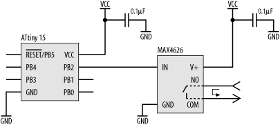
The question is: will it work with an AVR? When operating on a 5V supply, the input to the MAX4626 (pin 4, IN) requires a logic low input of less than 0.8V, and a logic high input of at least 2.4V. The AVR’s logic low output is 0.6V or less, and its logic high output is a minimum of 4.3V. So, the AVR’s digital output voltages match the requirements of the MAX4626. As for current, the MAX4626 needs to sink or source only a minuscule 1μA. For an AVR, this is not a problem.
If the MAX4626 doesn’t suit, MAXIM and other manufacturers produce a range of similar devices with varying characteristics. There’s bound to be something that meets your needs.
The schematic in Figure 6-6 shows a push button connected to PB3, where PB3 is acting as a digital input. Now, there are a couple of interesting things to note about this simple input circuit. The first is that there is no external pull-up resistor attached to PB3. Normally for such a circuit, an external pull-up resistor is required to place the input into a known state when the button is open (not being pressed). The pull-up resistor takes the input high, except when the button is closed and the input is connected directly to ground. The reason we can get away without an external pull-up resistor is that the AVR incorporates internal pull-up resistors, which may be enabled or disabled under software control.

The second interesting thing to note is that there is no debounce circuitry between the button and the input. Any sort of mechanical switch (and that includes a keyboard key) acts as a little inductor when pressed. The result is a rapid ringing oscillation on the signal line that quickly decays away (Figure 6-7).

So, instead of a single change of state, the resulting effect is as
if the user has been rapidly hammering away on the button. Software
written to respond to changes in this input will register the
multiple pulses, rather than the single press the user intended.
Removing these transients from the signal is therefore important and
is known as
debouncing
.
Now, there are several different circuits that you could include that will cleanly remove the ringing. But here’s the thing: you don’t always need to! When a user presses a button, he will usually hold that button closed for at least half a second, maybe more, by which time the ringing has died away. The problem can therefore be solved in software. The software, when it first registers a low on the input, waits for a few hundred milliseconds, then samples the input again (perhaps more than once). If it is still low, then it is a valid button press, and the software responds. The software then “rearms” the input, awaiting the next press. Debouncing hardware does become important, however, if the button is connected to an interrupt line or reset.
So far, we have seen how to use the AVR to control digital outputs and read simple digital inputs. The astute among you may ask, when looking at the previous two circuits, why do we need the processor? After all, it is certainly possible to connect the button directly to the input of the MAX4626. Of what use can the processor be? Well, we’ve already seen one use. The processor can replace debounce circuitry on the input. Since it has internal memory and the ability to execute software, the processor can also keep track of system state (and mode), can monitor various inputs in relation to one another, and can provide complicated control sequencing on the outputs. In short, the inclusion of a microprocessor can reduce hardware complexity while increasing system functionality. They can be very useful tools. With more advanced processors, and with more diverse I/O, the functionality and usefulness of an embedded computer can be significant.