
The PIC12C508 processor is a tiny 8-pin computer, designed for the simplest control functions. It can be used in any small application when you need to monitor digital inputs or turn something on or off. Its I/O pins could be used to synthesize a SPI or I2C interface (Chapter 9) or to control a motor (Chapter 12).
The processor’s internal program address space is shown in Figure 5-1.
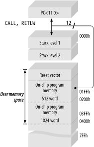
The PIC12C508 has 512 words of internal program memory and just 25 bytes of internal RAM.
Figure 5-2 shows the schematic for a small computer based upon the PIC12C508. The digital I/O signals of the PIC are brought out through a 7-pin connector. If the design were implemented using surface-mount components wherever possible, the connector would be the largest component on the PCB!

This particular PIC also includes an internal RC oscillator that runs at 4MHz, so we can use this processor without any external oscillator circuit. The design in Figure 5-3 shows the same PIC-based design, but this time using an external 32kHz watch crystal for its oscillator. By running off a (slower) 32kHz crystal, we have the advantage of greatly reducing the processor’s power consumption. This is important for battery-powered applications.

Two 15pF capacitors remove unwanted higher-order harmonics from the crystal’s oscillation. The values for the capacitors vary depending on what speed and type of crystal you are using. The processor datasheet has tables showing recommended capacitor values for various crystal frequencies.
Tip
The PIC processor has to be configured to use the appropriate oscillator source. When using the PIC with a 32kHz crystal, the chip has to be configured in “LP mode.” If you’re using the PIC with faster crystals (greater than 455kHz), the chip has to be in “XT mode.” The internal RC oscillator is selected by “INTRC mode,” while an external oscillator requires “EXTRC mode.” The Microchip development software (MPLAB) allows you to easily set these parameters when burning software into the processor.
The alternative clock source is an external RC circuit (Figure 5-4). While not the most precise timing option, it is by far the cheapest. The actual frequency of oscillation depends on a combination of the values of the resistor, the capacitor, the supply voltage, the variation in tolerances for the components, and the current operating temperature. To be clear, only an approximate operating frequency can be determined for an RC oscillator. For stable operation, Microchip recommends that the resistor should be between 3kΩ and 100kΩ, and the capacitor greater than 20pF. If you wish to use an external RC oscillator, refer to the processor’s datasheet, as Microchip has detailed information on RC component selection, taking into account voltage and temperature effects.

One of the neat tricks about using an external RC oscillator is that you can have a variable-speed computer. This is accomplished by adding a pull-up resistor (R1) between the oscillator input and an I/O pin (Figure 5-5). For normal operation, the I/O pin is configured as an input. By configuring the I/O pin as an output and placing it high, the resistor R1 is effectively placed in parallel with the resistor R. The overall resistance is increased by the relationship:
RTOTAL = 1 / (1/R + 1/R1)
and the oscillator slows accordingly. This is a useful technique to reduce power consumption under software control.

When using an external RC circuit to drive the internal oscillator, an extra PIC I/O line (GP4) becomes available for use.
No external reset is needed for this PIC. Instead, the design relies upon the internal power-up reset circuit of the processor. Further, not even an external resistor is required on the reset input, MCLR, since the processor incorporates a weak pull-up resistor for this purpose. When not used as a reset input, MCLR can be utilized as a general-purpose input.
Warning
MCLR on other PIC processors does require either a pull-up resistor or direct connection to VDD. Leaving it unconnected will not work, nor can it be used as a general-purpose input. Always check the datasheet!
The power supply (VDD) for the PIC12C508 can range from 2.5V to 5.5V.
That covers the basics of a PIC12C508 system, and it’s not that much different from the corresponding AVR computer, which we’ll look at in the next chapter. The real differences lie in their internal architectures (and instruction sets) and in the subtleties of their operating voltages and interfacing capabilities. As you can see, there’s not a lot of hard work involved in putting one of these little machines into your embedded system.