
Inductors are passive components
that are essentially a coil of conductive wire. The schematic symbol
for an inductor is shown in Figure 2-21. Inductance
is measured in
Henrie
s,
with an equation symbol L and a unit symbol H.
The voltage across an inductor changes the current flow through it, by the following relation:
V = L * dI/dt
Whereas applying a current to a capacitor caused the voltage to build across it, the opposite is true for an inductor. Applying a voltage across it builds current flow through it, and the resulting energy is stored in the inductor as a magnetic field. When the applied voltage is removed, the field collapses and returns the stored energy as a voltage spike.
Figure 2-22 shows a series R-L circuit.

The voltage across the resistor (VR) and the voltage across the inductor (VL) are shown in Figure 2-23. When a voltage is applied at VIN, the voltage across the resistor is initially small, whereas the voltage across the inductor is large. As the current flow through the inductor builds, the voltage across the resistor increases, while the voltage across the inductor diminishes accordingly.

Figure 2-24 shows a series R-L-C circuit.

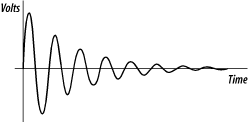
The response (VOUT versus time) of an R-L-C circuit to a step input is shown in Figure 2-25.

Figure 2-26 shows an R-L-C circuit in which all the components are in parallel.

The step response of this circuit is shown in Figure 2-27.
Inductors are commonly used in switching voltage regulators (Chapter 3) and are also employed (in combination with a resistor and capacitor) as filters to remove unwanted frequency components from a signal. Inductive effects exist in many components, and inductive voltage spikes are the bane of the embedded system designer.