
RS-232C is a serial communication interface standard that has been in use, in one form or another, since the 1960s. RS-232C is used for interfacing serial devices over cable lengths of up to 25 meters and at data rates up to 38.4kbps. You can use it to connect to other computers, modems, and even old terminals (useful tools for monitoring status messages during debugging). In days of old, printers, plotters, and a host of other devices came with RS-232C interfaces. With the need to transfer large amounts of data rapidly, RS-232C is being supplanted as a connection standard by high-speed networks, such as Ethernet. However, it can still be a useful and (importantly) simple connection tool for your embedded system.
RS-232C is unbalanced, meaning that the voltage level of a data bit being transmitted is referenced to local ground. A logic high for RS-232C is a signal voltage in the range -5 to -15V (typically -12V), and a logic low is between +5 and +15V (typically +12V). So, just to make that clear, an RS-232C high is a negative voltage, and a low is a positive voltage, unlike the rest of your computer’s logic.
The terminology used in RS-232C also goes back to the 1960s. In those days of mainframes, a high (1) was called a “space” and a low (0) was called a “mark.” You’ll still find these terms kicking around in RS-232C, where you’ll hear phrases like “mark parity” and “space parity.” It’s also not unheard of to see RS-232C systems still using 7-bit data frames (another leftover from the ’60s), rather than the more common 8-bit. In fact, this is one of the reasons you’ll still see email being sent on the Internet limited to a 7-bit character set, just in case the packets happen to be routed via a serial connection that supports only 7-bit transmissions. It’s nice how pieces of history still linger around to haunt us! More commonly, RS-232C data transmissions use 8-bit characters, and any serial port you implement should do so too.
An RS-232C link consists of a driver and a comparator, as shown in Figure 10-3.

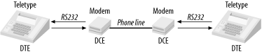
RS-232C also defines connectors and pin assignments, although there is a lot a room for variation (thus a lot of incompatibilities exist). RS-232C was originally intended for connecting Data Terminal Equipment (DTE) to Data Communication Equipment (DCE) (Figure 10-4). The standard therefore assumes that at one end of an RS-232C link is a DTE device and, the other, a DCE. Before the advent of computers, a DTE was a terminal or teletype and a DCE was a modem. The modem (MOdulator-DEModulator) provided an interface to the phone line and thereby a connection to a remote modem and terminal.
This worked simply and clearly in the days before desktop computers. The problem arises when you wish to connect either a terminal or a modem to the serial interface of a computer. Do you treat the computer as a DTE or a DCE? The RS-232C standard implies that if a terminal is at one end of the link, then the other end should be a DCE. So, if you were connecting a terminal to a Unix workstation, the RS-232C standard would like the workstation to be a DCE (Figure 10-5). Conversely, if you were connecting a modem to a computer, the computer should be a DTE (Figure 10-6). It’s all a bit schizophrenic.


Manufacturers, when faced with this problem, arbitrarily chose one or the other. The IBM PC has a DTE-type connector, whereas the makers of Unix workstations (such as Sun Microsystems) often chose to make their machines with DCE connectors, since they are more likely to be connected to terminals. To connect a PC to a modem, you need a DTE-DCE cable. To connect a PC to a terminal, you need a DTE-DTE cable. To connect a Sun workstation to a terminal, you need a DCE-DTE cable. To connect a Sun to a modem, you need a DCE-DCE cable. To connect a Sun to another Sun, you need a DCE-DCE null modem cable (where Rx and Tx cross over), and to connect a Sun to a PC, you need a DCE-DTE null modem cable. If, however, you need to connect two PCs together, you need a DTE-DTE null modem cable. So, for just two types of device (DTE and DCE), you need six types of cables to cope with the permutations! Variety, as they say, is the spice of life, but it’s the bane of RS-232C!
Table 10-1 shows the “standard” connections for RS-232C, for both 25-pin and 9-pin connectors. The signal names are DTE relative. For example, Tx refers to data being transmitted from the DTE but received by a DCE.
Table 10-1. RS-232C signals
|
Signal |
Function |
25-pin |
9-pin |
Direction |
|---|---|---|---|---|
|
Tx |
Transmitted data |
2 |
3 |
From DTE to DCE |
|
Rx |
Received data |
3 |
2 |
To DTE from DCE |
|
RTS |
Request to send |
4 |
7 |
From DTE to DCE |
|
CTS |
Clear to send |
5 |
8 |
To DTE from DCE |
|
DTR |
Data terminal ready |
20 |
4 |
From DTE to DCE |
|
DSR |
Data set ready |
6 |
6 |
To DTE from DCE |
|
DCD |
Data carrier detect |
8 |
1 |
To DTE from DCE |
|
RI |
Ring indicator |
22 |
9 |
To DTE from DCE |
|
FG |
Frame ground (chassis) |
1 |
- |
Common |
|
SG |
Signal ground |
7 |
5 |
Common |
Many of these signals are intended for modem control. To form a very simple link between a computer and a terminal, the only signals required are Tx, Rx, and SG. Many systems tie FG and SG together.
When two remote systems are
communicating serially, the transmitter
must be prevented from sending new data before the receiver has had a
chance to process the old. This process is known as
handshaking, or flow
control. The way it works is simple. After transmitting a
byte (or data packet), the transmitter will not send again until it
has been given confirmation that the receiver is ready. There are
three forms of handshaking: hardware, software, and none.
The no-handshaking option is obviously the most simple and is used when the transmitting system is much slower in preparing and sending data than the receiver is in processing. For example, if you had a small, embedded computer running at a pokey 1MHz and feeding data into a high-speed computer system running at 1GHz, you could assume that the faster machine would be able to keep up. However, if the faster machine is running a certain popular operating system (renowned for poor responsiveness to real-time events), it may very well not be able to keep up. In this case, handshaking would be required, and it’s probably good practice to incorporate it anyway. If you’re using the serial port to provide a human interface to your computer, then you can safely assume that no human will type faster than your computer can handle. So, for serial ports used solely for user access or debugging purposes, you can skip the handshaking.
Hardware handshaking in RS-232C uses two signals, RTS (Request To Send) and CTS (Clear To Send). When the transmitter wishes to send, it asserts RTS, indicating to the receiver that there is pending data. The receiver asserts CTS when it is ready, indicating to the transmitter that it may send. In this way, the flow of data is limited to the rate at which it may be processed.
Software handshaking, also known as
XON/XOFF
,
is used when hardware handshaking between the transmitter and
receiver is not possible, such as when the transmission occurs over a
phone line. Software handshaking chooses two characters to represent
a request to suspend transmission, and a
clear to resume. These are normally the
characters Ctrl-S (0x13) and Ctrl-Q (0x11). The caveat is that you
then can’t have these characters as part of the
transmitted file, for they would be interpreted as flow control by
the receiver and not as received data. If you’re
sending only ASCII text, this is not a problem, but it can be a real
headache if you’re sending binary data. The common
solution is to preprocess the binary data prior to transmission and
convert it to ASCII representation. For example, the byte 0x2F
becomes the ASCII characters “2”
(0x32) and “F” (0x46). Software on
the receiving end converts the ASCII characters back into binary data
again. Examples of software that will
do this are
uuencode under Unix and BinHex
under Mac OS.
Adding an RS-232C interface to a system is easy. Most microcontrollers (except only the very tiny) incorporate a UART within the chip, so all that is required is an external level shifter to convert the serial transmissions to and from RS-232C levels. Maxim makes a huge range of RS-232C interface chips (level shifters) that greatly simplify your design. No matter what your specific conversion requirements, doubtless there’s a Maxim part to meet your need. A good generic choice is the MAX3222 transceiver. Since nearly all RS-232C transceivers are used in the same way, looking at a design with a MAX3222 provides a good example of what to do for any transceiver. Unlike many other level shifters, the Maxim parts can operate from a low supply voltage, in the range 3.0V to 5.5V. Many other manufacturers’ devices need supplies of +12V and -12V and therefore require additional voltage regulators. The MAX3222 consumes minimal power (1mA in normal operation and as low as 1μA in shutdown mode), making it ideal for portable and battery-powered applications. If you do not need to shut down the serial port into low-power operation, the MAX3232 can be substituted. It is functionally the same, except that it lacks shutdown capability.
Using the MAX3222 is trivial, as there is almost no design work involved at all. The only external support components required are capacitors for the chip’s internal charge pumps. These pumps generate the +12V and -12V voltages required for RS-232C transmission, without requiring (additional) external voltage regulators. Figure 10-7 shows the schematic.

The capacitor C1 must be a minimum of 0.1μF. If operating the chip at less than 3.6V, C2, C3, and C4 can also be 0.1μF. If the supply voltage is to be as high as 5.5V, the C2, C3, and C4 must be a minimum of 0.47μF. Since these are minimum values, larger capacitors may be used. However, if C1 is increased, then the remaining capacitors must also be increased accordingly. C5, the decoupling capacitor for VCC, is nominally 0.1μF. All capacitors should be as close to the appropriate pins of the chip as possible.
The only remaining connections are the serial data lines from the UART and the signals to the RS-232C connector. If implementing a minimal serial interface, only Rx, Tx, and ground are required. RTS (Request to Send) and CTS (Clear to Send) are optional. The RS-232C connector may be either a 25-pin or a 9-pin DB connector (it looks like the letter D in shape). However, the connector could also be just a row of pins, a parallel header, or even just wires soldered directly onto the PCB.
The MAX3222 has two control inputs, SHDN (shutdown) and EN (enable). SHDN places the RS-232C transmitters in high impedance, thereby disabling them. This reduces the chip’s current consumption to less than 1μA. When in shutdown mode, the receivers are still active. Thus, the UART is still able to receive data even if the MAX3222 is in low-power mode. If SHDN is not required, just connect it directly to VCC.
Similarly, EN is used to control the receiver outputs. Placing EN high puts the receiver outputs into high impedance, while the transmitter outputs are unaffected. To enable the receivers, EN is asserted (pulled low). If disabling the receivers is not required, then tie EN to ground to permanently activate them.
If needed, SHDN and EN may be controlled by a microcontroller’s I/O lines or by simple digital outputs using a latch.
The MAX3222 is sufficient to implement a minimal RS-232C interface, using just Rx, Tx, and ground. It also has additional drivers to support RTS and CTS, allowing for basic flow control. Should you require a full RS-232C interface, the MAX3241 is a good choice. Its operation is similar to the MAX3222, but it has additional transceivers allowing the inclusion of DTR, DSR, DCD, and RI for modem control. The MAX3421 may also be used to interface to a serial mouse, since it is able to meet the appropriate voltage and current requirements.
If an embedded system is to be permanently connected to a host computer via an RS-232C serial interface, the embedded system may be parasitically powered from the serial interface. Many RS-232C signals go unused and can supply a moderate amount of current (nominally 50 mA, but it can vary and, as always, you should check the specific device to which you are interfacing). If your embedded system requires less than this for its total current draw, you can use an RS-232C control signal for power.
For instance, the RTS (Request To Send) or DTR (Data Terminal Request) signals may not be used in many RS-232C applications. Either can be used as the power input to a voltage regulator and thereby provide the system with power. The host computer therefore uses RTS of its serial port as the power control for the embedded system. Under software, the host sends RTS high, and the embedded system is powered up. Send RTS low, and the embedded system is switched off. The catch to all this is to ensure that your embedded system’s current draw is low enough so that it can be powered by RTS. The advantage of this technique is that you require no external power supply for your embedded system. It works, as if by magic, whenever plugged into a serial port. The other catch is that you can’t then use that RS-232C control signal for its original purpose. It must turn on and stay on to provide your computer with power.
The schematic for this is shown in Figure 10-8, which also includes an RS-232C interface for a microcontroller, using a MAX3232. Note the diode, D1. Since RTS will be a negative voltage (as low as -15V) when low, some protection is required for the voltage regulator, since it is not designed to have its input taken below zero volts. The diode can be any garden-variety power diode, such as a 1N4004, and will conduct only when RTS is positive. The voltage regulator (MAX604) converts the voltage from RTS to a supply of 3.3V for the embedded system. If we required a supply of 5V, we’d simply use a MAX603 instead. The circuit would otherwise be the same. The output of the regulator is smoothed by the capacitor C5, and a power-on LED is provided to show us when we have power. The MAX3232 sits between the RS-232C port and the processor, level-shifting the serial transmissions from the processor’s logic levels to RS-232C and vice versa.

There we have the basics of RS-232C. It’s a very common interface that is easy to use, but it does have its limitations and quirks. It was originally intended for connecting dumb terminals and teletypes to modems, not for interconnecting computers and peripherals. A better choice is RS-422, designed for more robust and versatile serial connections.