Chapter 13. Distributed Architectures
Previous chapters have described the implementation of a single, simple node. A node is the smallest executable standalone unit consisting of a running instance of the Erlang runtime system. In this chapter we start to show how to expand from single nodes to distributed systems comprising multiple nodes. We try to help you figure out how to achieve availability, scalability, and consistency across these nodes. These qualities go hand in hand with reliability, which ensures that your system behaves correctly even under abnormal circumstances such as failure or extreme load.
Each node consists of a number of loosely coupled OTP applications, defined in its OTP release file. An OTP release determines the services the node provides and tasks it is capable of handling. Nodes that share a release file contain the same set of OTP applications and are considered to be nodes of the same type.
Nodes of one type can interact in a cluster with other node types to provide the system’s end-to-end functionality. An Erlang system can comprise just one standalone node, but more typically consists of multiple nodes grouped in one or more clusters.
Clusters are needed for a variety of reasons. You might be implementing a microservices architecture, where each cluster of nodes provides a set of services. Or you might use clusters for scalability, sharding across identical clusters to increase computing power and availability. When dealing with distributed Erlang systems, which run on hybrid target environments in potentially geographically remote data centers, there is no single solution that fits all contexts. The lack of a single solution also means that tools and frameworks dealing with monitoring, management, and orchestration of Erlang nodes have to cater to different cluster patterns. Some tools might be ideal when dealing with deployments on Amazon or Rackspace, but they will not work on Parallela or Raspberry Pi clusters. Other tools will work best when deploying on bare metal, but not as well in virtual environments.
In this chapter and the next few, we cover the first steps involved in designing your distributed architecture. This chapter starts by looking at Erlang node types and describes how they are grouped together and interact with each other. This should help you determine how to split up your system into standalone nodes, each offering specific services. We describe the most common distributed architectural patterns used to provide these services and introduce some of the most popular distributed frameworks, such as “Riak Core” and “Scalable Distributed Erlang”.
Although distributed Erlang will work out of the box, it is not always the right tool for the job. We cover other networking approaches you might need when connecting your Erlang and non-Erlang nodes to each other. We conclude by giving you a high-level approach on how to start defining the interfaces and data models of the individual node types.
Node Types and Families
Until recently, there were no common definitions covering distributed Erlang systems. OTP did a great job defining the individual components of a single node, but stopped short of describing how nodes are grouped together and how they interact in clusters. Although there was no ambiguity when developers in remote parts of the world spoke about generic servers, applications, or releases, confusion arose when trying to discuss clusters, the roles of nodes in clusters, or scalability patterns. These definitions were discussed and formalized1 as part of the RELEASE project, EU-funded research addressing the scalability of the Erlang VM in distributed, many-core architectures. Before we start talking about distributed architectures, let’s define our terminology.
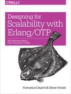
Imagine a system consisting of three Erlang nodes. The first node runs web servers that keep pools of TCP connections open toward the clients. Clients could be mobile apps or web browsers. This receives HTTP requests, parses them into Erlang terms, and forwards them to a second node that handles the business logic of the system.
In handling the requests, the second node might interact with other nodes, each providing some form of service. For the sake of simplicity, let’s assume it’s a database node, possibly (but not necessarily) written in Erlang. To the end user, this all appears as a single system accessed as a black box. Erlang, the multiple nodes, and the distribution layer among the nodes are all hidden from the client users.
Figure 13-1 is an example of three semantic node types that classify the functionality and purpose of the nodes in the cluster. Multiple node instances of the same type could be running different versions of the same release. We run multiple instances of a single node for availability and scalability. We cover these topics in more detail in Chapter 14 and Chapter 15.
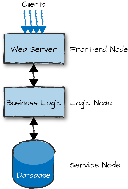
Figure 13-1. Semantic node types
The web server node is what we refer to as a front-end node. Front-end nodes are responsible for providing external connectivity to clients and handling all incoming requests. They act as gateways, keeping client connections open as needed, formatting inbound requests and outbound responses, and passing the requests onward to the nodes handling the business logic. They are part of the server-side software, serving, but not running, the presentation layer.
Logic nodes, also commonly referred to as back-end nodes, implement the system’s business logic. They contain all of the code needed to handle client requests forwarded from the front-end nodes. They might also cache session data and access external services in other nodes when handling requests.
Finally, we have service nodes, which provide a service to the logic nodes. Such a service could be a database, an authentication server, or a payment gateway. Service nodes could themselves provide connectivity toward third-party services and APIs.
Node types are merely a way for us to describe the overall responsibility of each node. A single node, especially in small or simple systems, could have multiple responsibilities and act as both front-end and logic node, and even a service node, all in one. Think of a node that runs an Erlang web server (such as Yaws, Webmachine, or Cowboy), Erlang/OTP glue and business logic, and an Erlang database (such as Mnesia, CouchDB, or Riak) all in the same virtual machine. Combining all such applications into a single node like this reduces internode I/O and networking overhead by running everything in the same memory space, but it also produces a single point of failure and an architecture that might not scale. In contrast, in a multinode system, the responsibilities of the node types are spread across multiple nodes for maintainability, scalability, and availability.
When splitting your functionality into node types, try to keep memory-bound and CPU-bound functionality in separate nodes. That facilitates the fine-tuning of the VM and gives you flexibility in choosing the underlying hardware, optimizing for cost and performance. It also allows you to minimize the risk of a system failure, because not only are simple nodes easier to implement and test, but when they do fail, they will not affect the other nodes to the same extent as if all applications were running in the same node. A surge in simultaneous requests that causes a node to run out of memory should not affect the user database or the client connections. (We discuss how to handle surges in “Load Regulation and Backpressure”.)
We group node types running the same OTP release into a node family. This is a way of managing nodes as a single entity. You can have different node families with the same release, but grouped together based on criteria such as data center, cloud region, or even release version. Node families are then grouped into clusters, which together give you your system. Multiple clusters in systems are used to increase availability, reliability, and scalability, spreading services geographically across different data centers, possibly managed by different cloud or infrastructure providers.
To better understand the role of individual nodes, let’s go into more detail using the example that we started looking at in Figure 13-1: an Erlang system that handles HTTP requests. We use it here and in the next two chapters to describe various concepts and tradeoffs we have to make when dealing with distributed systems.
Picture a system handling the back-end services of an e-commerce application. We focus on the login request originating from a client to the system. The client sends a login request using a RESTful API with data transmitted as JSON over HTTP. This request could originate from a mobile app or a web browser. The request is received by a web server running on the front-end nodes, which parses it into Erlang terms and forwards them to the logic node. The terms forwarded include the login request, the user ID, and the encrypted password.
The logic node checks the validity of the request and authenticates the user via an authentication server. If successful, a session ID and record are created and cached locally in the logic node. It returns the session ID back to the front-end server, which encodes it and returns it to the client with the acknowledgment that the login request was successful. The client uses the session ID in all subsequent communication for the duration of the session, and in each subsequent client request this ID is passed to the logic node and used to retrieve the record.
Regardless of whether you are using the three-layer architecture in Figure 13-1 or some other architectural pattern, the logic node is an important intermediary and checkpoint. Avoid having front-end nodes communicating directly with service nodes. Although it’s not illegal, it often leads to poor system structure and confusion when trying to understand the system from an architectural view.
We add multiple instances of node types in our architecture to create distributed cluster patterns, also known as system blueprints. If you are happy with a static architecture that scales by adding independent instances of the system that do not interact with each other, the blueprint is easy. If your system scales to 1,000,000 simultaneously connected users executing 100,000 requests per second, roll out one per country and route user requests by pairing the inbound IP address to a geographical location. But if your app is a global online store that scales dynamically based on peaks and troughs, elastically adding computing capacity in the run-up to events such as payday, Black Friday, and Christmas and then releasing it again when not needed, extra thought needs to be put into the system from the start.
Both static and dynamic approaches to node (and hardware) management in your cluster go hand in hand with the strategies of how you distribute your data across nodes, node families, and ultimately clusters. How you connect your nodes and clusters together also becomes important, as does your data replication strategy across them. Users are logged on to the system and shopping away. Do you keep copies of their session data in all nodes or just some nodes? And every time a customer adds an item to a shopping basket, how are the changes propagated to other nodes? What happens if there is a network partition or failure? Or what about a software error or a node terminating? We cover these design choices in Chapter 14. They boil down to tradeoffs between availability, reliability, consistency, and scalability. What you need to do early on is understand the compromises that fit the needs of the system you are architecting and the end-user experience you want to provide.
Networking
So far, we’ve been talking about front-end nodes communicating with logic
nodes, which in turn send requests to service nodes. We haven’t mentioned
distributed Erlang, because while it’s ideal for smaller clusters within
the same data center, it is not always the right solution when multidata
center deployments, security, availability, and massive scalability come
into the picture. In some cases, when lots of data needs to be
transferred, a single socket becomes a bottleneck and you might want to use pools of connections
found in libraries such as ranch or
poolboy. RESTful APIs give you platform independence, as do other protocols such as AMQP, SNMP,
MQTT, and XMPP. Distributed Erlang might still fit your needs, but rather
than running it over TCP you might want to use alternative carriers such
as 0MQ, UDP, SSL, or MPI.
In some systems, the network topology will go as far as providing different networks for different types of traffic. Traffic handling monitoring, billing, configuration, and maintenance would go through an operations and maintenance (O&M network), while traffic such as setting up of calls, instant messages, SMSs, or telemetry data would be routed through a data network. You would split them, as the data network would have higher bandwidth and availability requirements than the O&M one. You should avoid stopping or slowing down users playing a massively multiuser online game, but can get away with a delay in moving and processing billing records.
Demonstrating networking choices with our example will help clarify the choices you have to make. If you are concerned about security in your e-commerce site, you might want to place your front-end nodes in a demilitarized zone (DMZ), also known as a perimeter network (Figure 13-2). This is a physical or logical part of the network that exposes your nodes to an untrusted network (i.e., the Internet) used by the clients to access your services. DMZs were traditionally implemented in the hardware through the arrangement of managed network elements, and in the software using firewalls and other security measures. In cloud computing environments you do not get the hardware component, and have to instead mimic it through network connections and firewall rules. The end result, however, is still the same. By creating an additional layer of security around your back-end nodes, you reduce the risk of intrusion in your logical and service nodes by not exposing their interfaces.
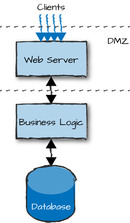
Figure 13-2. Demilitarized zones
If you were to use distributed Erlang, access to your front-end nodes would pretty much also mean access to your logic and service nodes as well. Gone are the days when no one knew about Erlang and when security through obscurity was enough to safeguard you. You must use sockets, possibly even encrypted sockets, between the web server and the nodes running the business logic, authenticating every request and checking its validity. Communication between the nodes running your business logic and your databases, however, takes place behind a firewall in what is considered to be a safe environment. The nodes can communicate transparently with each other using distributed Erlang.
Distributed Erlang
There are two approaches to implementing your architecture using distributed Erlang. A static cluster has a fixed number of known parameters with fixed identities (hostnames, IPs, MAC addresses, etc.). It isn’t provisioned to scale dynamically. In a dynamic cluster, the number of identities and nodes changes at runtime. In both cases, your system needs to be implemented with transitive connections in mind, because either network connectivity or the nodes themselves can fail (and restart). The only difference between a static and a dynamic system is that in the latter, alongside failing, nodes are started and stopped in a more controlled way. In a static system, they don’t stop unless they fail.
Distributed Erlang clusters that are fully connected (Figure 13-3) are ideal for systems of certain size and requirements, but as we have said many times before, there is no “one size fits all” solution. Based on your node configuration and the size and frequency of messages sent across nodes, fully meshed Erlang clusters scale at the time of writing to about 70 to 100 nodes before performance degradation starts becoming evident. When a new node is added to the cluster, information on all visible (nonhidden) nodes that share the secret cookie gets propagated to it, connections are set up, and monitoring kicks in. So, with 100 connected nodes, you get 5,050 TCP connections (100+99+...+2+1) and heartbeats across them all, creating overhead in both the node and the network. Other single-process bottlenecks exist as well, such as rex, which handles Erlang remote procedure calls (RPCs), or the net kernel, which remotely spawns processes and deals with network monitoring.
How far you are able to scale your fully meshed distributed Erlang cluster depends on the characteristics of your system. Hidden nodes, covered in “Node Connections and Visibility”, act as gateways stopping the propagation of information across clusters of fully meshed nodes. They provide you with isolation and scalability, but you have to build frameworks that sit on top of them. You might be better off looking at alternative approaches or existing frameworks such as Riak Core and SD Erlang, which are covered in the following subsections.
Finally, you can create a special build that uses SSL as a bearer of Erlang distribution instead of plain TCP. You can read more about it in the “Using SSL for Erlang Distribution” section of the Secure Socket Layer User’s Guide.
Figure 13-3. Distributed Erlang
Using Pids
If you are using process IDs instead of registered names across distributed Erlang clusters, keep in mind that if the remote node crashes and restarts, the pid on the restarted node might be reused. This could result in a process other than the intended one receiving your message. Always monitor remote nodes and processes, and take appropriate action if failure is detected. There is a counter for process IDs across nodes that gives you one or more generations of restarts with reused pids to avoid the problem, at least as long as the Erlang port mapper daemon (epmd) is alive.
Riak Core
Riak Core is a framework that provides an eventually consistent replicated data model on a system of masterless peer nodes providing high availability and helping guarantee no single point of failure. It is built on top of distributed Erlang and is the foundation of the distributed Riak key-value store, based on ideas from the 2007 Dynamo paper from Amazon. It is an ideal framework for systems that require high availability and the need to self-heal after node or network failures. Fully explaining all the details of Riak Core would require a book of its own, so we cover just the highlights that make it a serious contender in the distributed frameworks space.
Riak Core runs on a cluster of physical nodes overlaid with a system of virtual nodes, also known as vnodes. The number of vnodes is configurable, but a typical Riak Core cluster includes 15–20 physical nodes that collectively host 256 vnodes. Each vnode claims a range of the 160-bit integer space of the SHA-1 hash function, which Riak Core uses as the basis of its consistent hashing system. Consistent hashing spreads key-value data evenly across the cluster while minimizing the amount of data relocation required as physical nodes are operationally added to or removed from the cluster.
To store data in a Riak Core cluster, a client sends a write
request including both key and value. Riak Core hashes the key to
obtain its hash value, then determines which vnode owns the range of
160-bit values that includes that hash value. Because Riak Core
replicates each write, it first determines the replication factor for
the request, which is called N and typically
defaults to 3. It then stores N copies of the data,
one in that primary vnode and the rest in the vnodes that respectively
own the next N–1 hash ranges. Riak Core considers
the write complete when the number of written copies equals the write
factor, W. By default, W is
N/2+1, which is 2 if N is
3.
To read data from a cluster, a client sends a request including
the key. Riak Core first hashes the key to determine the primary vnode
that should be holding the requested value. It then requests the value
from that vnode and the N–1 next consecutive
vnodes, and waits for the read factor, called R, to
be fulfilled. Like W, by default
R is N/2+1, which is 2 when
N is 3. Once two copies of the value are
successfully read, Riak Core returns the requested value to the
client.
When a Riak Core cluster is first created, its physical nodes claim ownership of vnodes such that adjacent vnodes are not stored on the same physical node. Thus, by storing replicas in consecutive vnodes, and assuming the cluster comprises at least the minimum recommended five physical nodes, Riak Core tries its best to guarantee the replicas are stored on different nodes. Should any physical node crash or become unreachable, the other replicas can still respond to requests for reading or writing that data, thus providing availability even if the cluster is partitioned. The arrangement of vnodes on physical nodes is made clear in Figure 13-4, where, when looking up a value, the hash of the key points to the vnode, which in turn points to the primary Erlang node responsible for that value.
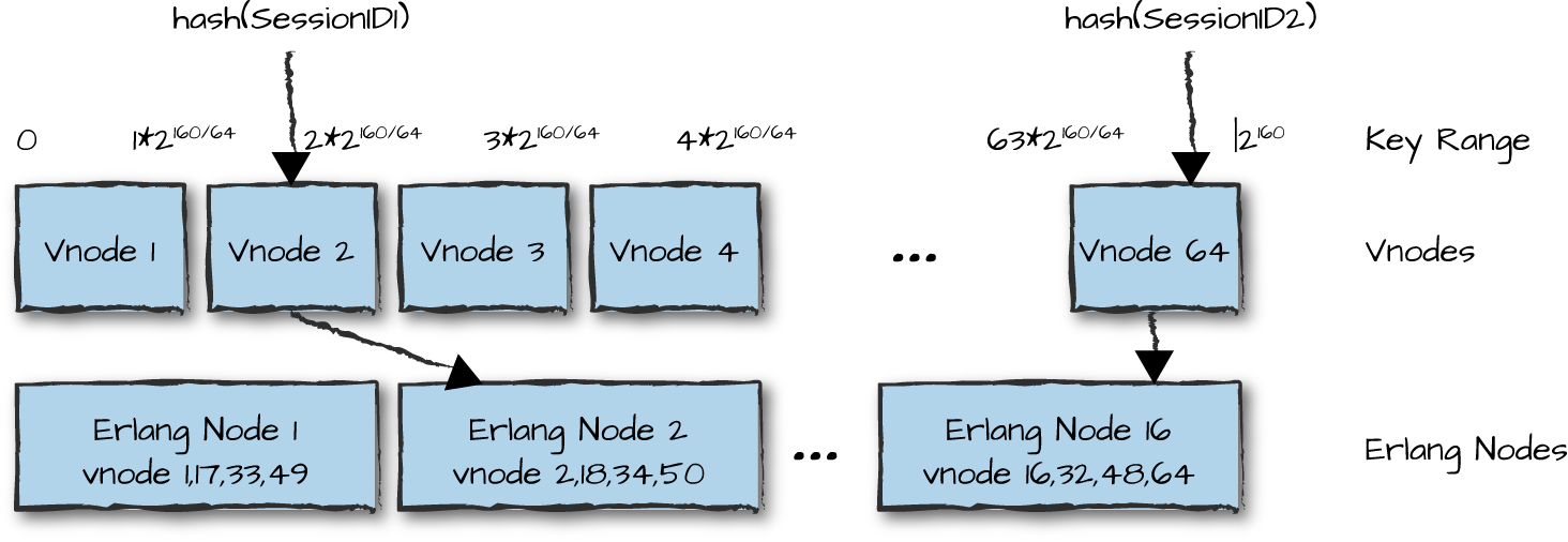
Figure 13-4. Vnodes
One advantage of using vnodes and consistent hashing pertains to the reshuffling that takes place when nodes get added or taken out of service. Assume that our cluster in Figure 13-4 has 16 nodes and we take node 1 permanently out of service. Riak Core redistributes vnodes 1, 17, 33, and 49 across existing nodes without needing to reshuffle all of the data across all nodes. The vnodes that are on the nodes still in service stay put. And if a new node is put into production, four vnodes will be moved to it from their current locations, affecting only the nodes where the vnodes are located.
Riak Core nodes are peers, and there is no master node. Nodes use a gossip protocol to communicate shared information such as cluster topology changes and the vnode claims to other randomly selected nodes. If updates to the cluster topology were missed on particular nodes for whatever reason, the gossip protocol forwards these changes, ensuring that the system heals itself.
Riak Core uses hinted
handoffs to ensure that N copies of the data are stored,
even if the primary vnode or some of the replica vnodes are down or
unreachable because of a network partition. In such a case, Riak Core
stores the data in an alternative vnode and gives that vnode a hint as
to where the data really should be stored. When the unreachable vnodes
again become available, the alternative vnodes hand the data off to
them, thereby healing the system. Hinted handoffs are part of Riak
Core’s sloppy quorums. Writes
require W acknowledgments to be
considered successful, and similarly reads are considered successful
with R results, but Riak doesn’t care whether those
quorums comprise primary or alternative vnodes (hence the term
“sloppy”). If Riak were to instead use strict quorums,
which consist only of primary vnodes, the result would be diminished
system availability when primaries were down or unreachable.
As soon as we start distributing data and states across replicas, we introduce uncertainty. How do we know an operation was successfully replicated to all nodes? What if, because of partitions or node, network, hardware, or software failures, data becomes inconsistent?
In cases where nodes return different values without achieving a quorum, Riak Core tries to resolve the conflicting values using dotted version vectors (DVVs). DVVs provide a way for Riak Core to identify a partial ordering of write events for a given value that can help determine which of the values is the correct one. This ordering is based not on timestamps, which are too unreliable and too difficult to keep synchronized across a cluster of nodes, but rather on logical clocks based on monotonically increasing counters at each node that acts on the value. If the DVV information is not enough to resolve the conflict, all conflicting values of the state are returned to the client as sibling values, and the conflict must then be resolved by the client application, presumably using domain-specific knowledge to make its decision.
So, how does Riak Core help us implement our distributed architecture? Although you are still limited to a maximum of a hundred nodes in your core, you can use these nodes as hubs or gateways to other clusters, as shown in Figure 13-5. Logic nodes running Riak Core create a fully meshed ring used for messaging, job scheduling, and routing requests to service nodes, or to act as gateways to other clusters.
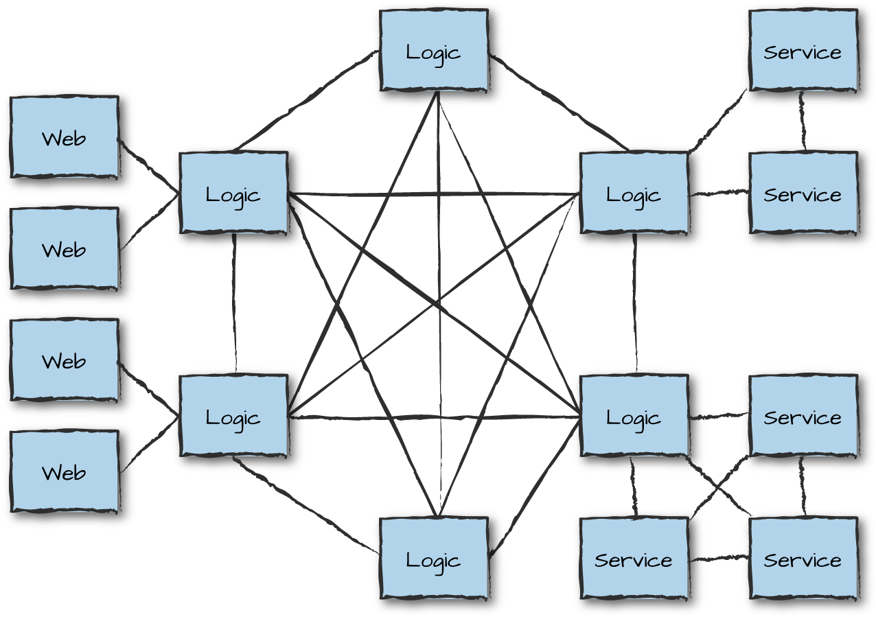
Figure 13-5. Riak Core patterns
Figure 13-6 uses another approach for massive scalability: a star architecture, where service nodes connected to each other can be used for storage and analytics purposes, increasing and decreasing in size dynamically based on load. Both patterns serve their purpose and overcome the scalability issues encountered with fully meshed networks. More complex patterns are available as well, as are simpler ones. Some include running multiple Riak Core clusters connected to each other via hidden nodes acting as gateways.
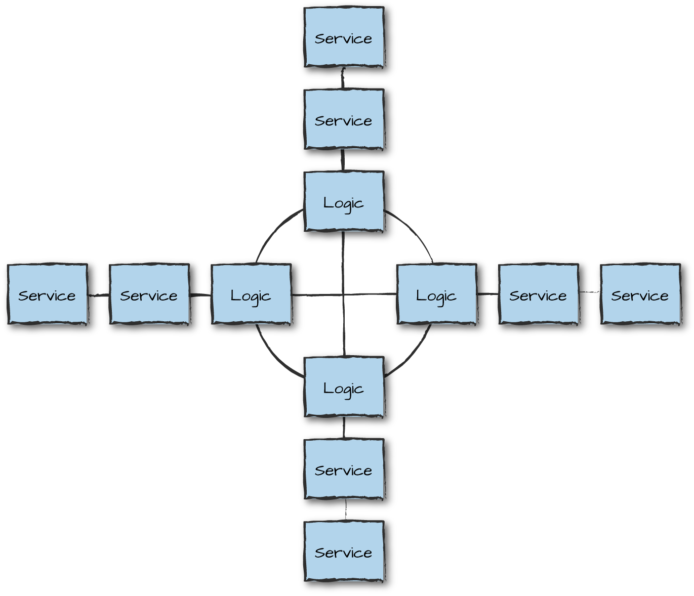
Figure 13-6. Riak Core star
If consistent hashing and Riak Core are the right approach for
the problems you’re solving, you may also want to look at the NkCLUSTER
application, a layer on top of Riak Core written to create and manage
clusters of Erlang nodes and to distribute and schedule jobs on the
cluster. NkDIST is a
library that evenly distributes processes, automatically moving
them when the Riak Core cluster is rebalanced through the addition or
removal of nodes. You can find NkDIST and
NkCLUSTER documentation in their respective GitHub pages
and repositories.
For further reading on Riak Core, we recommend Mariano Guerra’s Little Riak Core Book on GitHub. You can read the official documentation on Basho’s website (Basho is the company that created and maintains Riak Core). A web search will also reveal many talks and tutorials. And finally, an excellent example of how to use Riak Core is Udon, a distributed static file web server by Mark Allen.
Scalable Distributed Erlang
Scalable Distributed Erlang (SD Erlang) takes a different approach from that of Riak Core. SD Erlang emerged from the RELEASE research project at the University of Glasgow. Although at the time of writing it was not production-ready, the ideas behind it are interesting and have been shown to allow systems to scale to tens of thousands of nodes. The basic approach is to reduce network connectivity and the namespace through a small extension to the existing distributed Erlang.
SD Erlang defines a new layer called an s_group. Nodes can belong to
zero, one, or more s_groups, and nodes that belong to the same s_group
transitively share connections and a namespace. A
namespace is a set of names registered using the
global:register_name/2 function in distributed Erlang or the
s_group:register_name/3 function in SD Erlang. Names
registered in distributed Erlang are replicated on all connected
normal (not hidden) nodes. In SD Erlang, the name is replicated on all
nodes of the given s_group.
Figure 13-7 shows two s_groups named G1 and G2. Each contains three Erlang nodes. Because node C is shared by both s_groups, it can transmit messages between nodes in different s_groups. Node C is called a gateway.
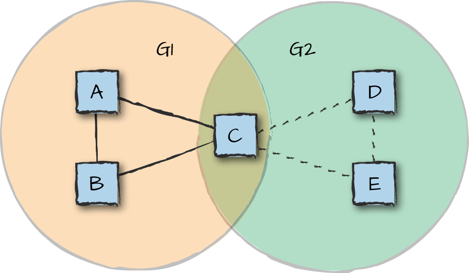
Figure 13-7. SD Erlang groups
Using the SD Erlang concept of node groups, a programmer can arrange nodes in different configurations, e.g., clustering nodes and connecting them via gateways.
To enable SD Erlang applications to be portable and scalable, a concept of semi-explicit placement is also introduced. This controls the placement of new nodes based on communication distances to other nodes and on node attributes. Node attributes are hardware-, software-, and programmer-defined characteristics of nodes that enable them to be aware of their unique characteristics and their neighboring nodes. Communication distances use the time it takes to transfer data from one node to another as a metric. Assuming connections with equal bandwidth, shorter transfer times correspond to smaller communication distances between nodes.
Documentation about SD Erlang is available on the University of Glasgow’s site. Lots of conference talks and articles about it are also available online.
Sockets and SSL
There will be times when distributed Erlang is not enough. On extremely
high volume systems, bottlenecks can occur in the global name server, rex, or the net kernel—not to mention the
distributed Erlang port itself, which, even if fast, is capable of
handling only one request at a time, as it’s designed for control
messages rather than for data transfer. Or, as we saw in our DMZ
example, you might want to avoid distributed Erlang for security
reasons, limiting the openness the fully meshed network brings to the
table. When distributed Erlang is not the right tool for the job, adding
a thin layer above the ssl or gen_tcp
libraries starts making sense. You open one or more sockets between
the nodes, controlling the flow of information sent and received.
Bottlenecks can also occur when moving large volumes of data with sockets. As an example, we were once working with a system that managed instant messages. The instant messages tended to be short and bursty, so a single TCP connection from our DMZ coped well under extreme load. When we upgraded the same system to also manage email, queues quickly started building up in the front-end nodes when exposed to continuous heavy load. This had to do with the sizes of the messages being sent, which were much larger than the instant messages, causing the TCP socket processes to back up. The backup eventually caused the virtual machine to run out of memory. The network was far from saturated, so adding multiple connections between the front-end and logic nodes (Figure 13-8) got rid of the bottleneck.
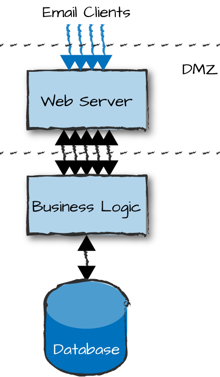
Figure 13-8. Communication bottlenecks
Typical use cases where we’ve had to use multiple connections across nodes include the transfer of images, logs, or emails and email attachments. The volumes of data have to be substantial for multiple connections to pay off, though, so avoid premature optimization. Start with a single connection and add more only when you have metrics showing you have a problem that multiple connections can fix.
This is a common approach for which there are a few open source
libraries. The gen_rpc
application on GitHub has been benchmarked doing in excess of 60,000 RPC
requests per second. If you need simple functionality, you can also
write your own connection API. In its simplest guise, such an API would
be a thin layer consisting of a few dozen lines of code that is highly
optimized for the traffic and security requirements of your
applications. That said, it might make sense to base your socket library
on a process pool library such as Poolboy.
The example in Figure 13-2 illustrates the security
rationale for not always relying on Erlang to distribute processing. We
would not want the front-end nodes communicating with the logic nodes
using distributed Erlang, because an intruder who gained access to the
stateless client nodes would also gain full access to all the connected
nodes and be able to execute OS-level commands on the remote machines.
Just imagine someone obsessed by tidiness executing rpc:multicall(nodes(), os, cmd, ["rm -rf
*"]) in order to enjoy the peace and serenity a clean hard drive
brings.
Even if you roll out your own TCP- or SSL-based communication library between the front-end and logic nodes, you can still use distributed Erlang to let the logic nodes communicate with each other and share data through Riak, Mnesia, or simple message passing. In turn, the logic nodes might use RESTful approaches to communicate with service nodes. When your system starts getting complicated, mixing communication methods for security, performance, and scalability purposes becomes common. The mix could be between nodes, node types, or node families.
Service Orientation and Microservices
Another pattern for creating systems that scale is microservices and service-oriented architectures (SOA). Although SOA is considered heavyweight and old-fashioned by some, it is widely used in enterprise systems and its ideas are fundamental to microservices. Both are similar in concept to the client-server paradigm where processes and nodes (or node families) provide services to other nodes and processes. These services, often standalone or loosely coupled, together provide the functionality required by your system. They are often expressed in terms of an API, where each service (or function) implements an action invoked by a node requesting the service. The services provided are the same as those we have looked at already in this book. They could include client front-end interfaces, authentication databases, logging, alarming, logic nodes, and other service nodes (Figure 13-9). Services should be packaged in a generic enough way to encourage reusability not just among other services, but also across systems.
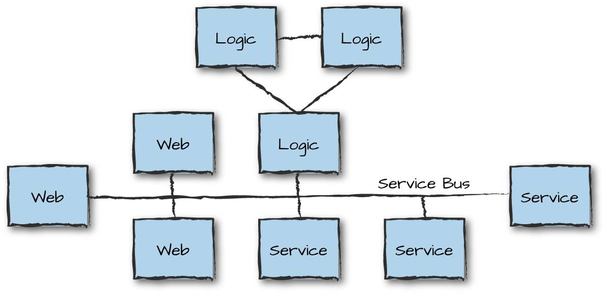
Figure 13-9. Service-oriented architectures
Services are connected together by a service bus. They use a protocol that describes how services exchange and interpret messages. This is done with service metadata, which describes what each service does and the data it requires. The metadata should be in a format that allows nodes to dynamically configure and publicize their services, which in turn allows other services to dynamically discover and use them. The messages themselves are often defined using JSON, XML, Protocol Buffers, Erlang terms, or even OMG IDL.
The service bus runs over a network and allows communication following a particular protocol. Requests can be sent using SOAP, HTTP, or AMQP. You could use web services, Java RMI, Thrift bindings, or even Erlang-based RPCs and message passing. Certain message buses have the added benefit of helping throttle requests and dealing with load regulation and backpressure. We cover these concepts in more detail in “Load Regulation and Backpressure”.
The advantage of standardized protocols is that they allow you to combine ready-made components or standalone nodes, possibly implemented in multiple programming languages. At the same time, they force you to package your services in a way that encourages reusability across systems. This does, however, come at the cost of overhead in the size of the data shared across nodes as well as the encoding and parsing of the requests and replies.
Peer to Peer
Peer-to-peer (p2p) architectures are probably the most scalable distributed architectural patterns of all, as they are completely decentralized and consist of nodes of the same type that set up ad hoc connections to other nodes. Every node has the same privileges, capabilities, and responsibilities, in contrast to client-server architectural patterns, where the purpose of some node types is to serve other node types.
In p2p architectures, every node is both a client and a server, allowing it to start a communication session in a decentralized way. Think of protocols such as BitTorrent, Gnutella, Gossip, and Kazaa. While to the masses, p2p is synonymous with file sharing, its use in the Erlang world is more associated with massively parallel computations, distributed file storage, and big data analytics. P2p nodes tend to form connections in unpredictable and rapidly changing ways, but with low overhead (Figure 13-10). However, passing data through multiple nodes to get to its ultimate destination can result in extra overall load on the network.
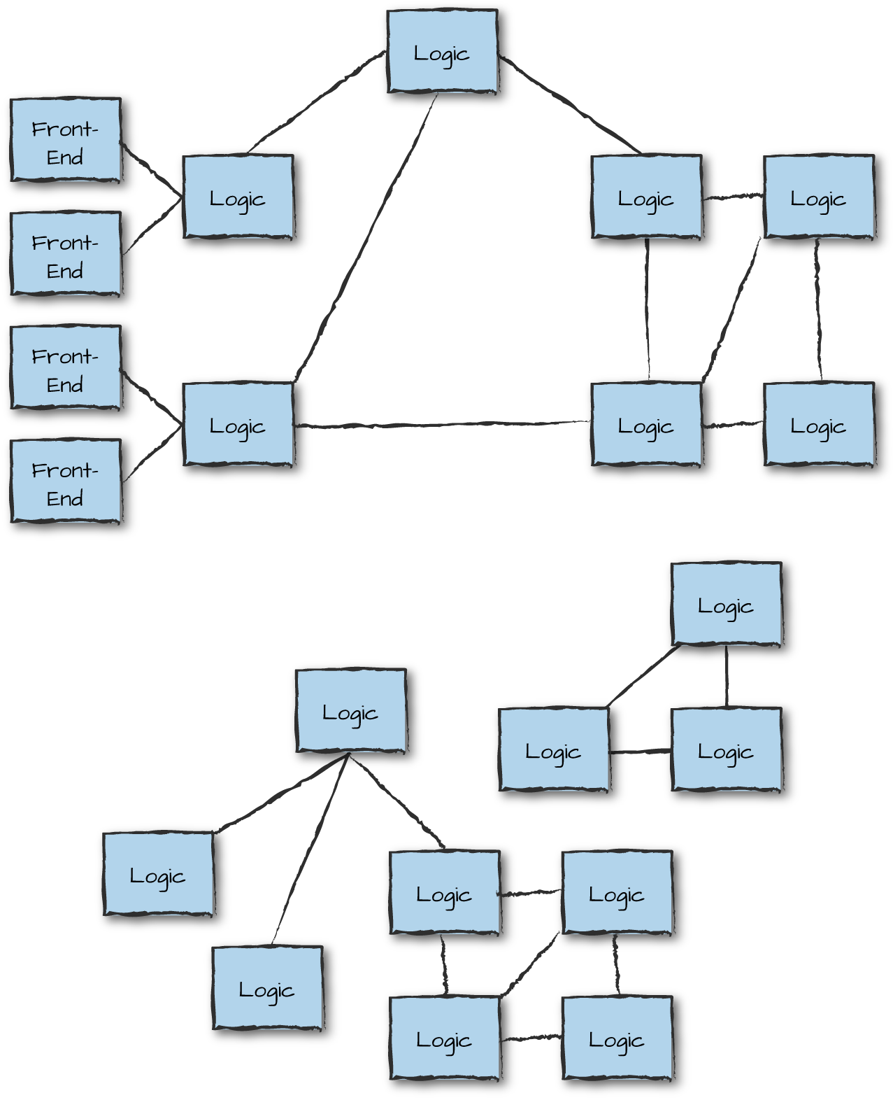
Figure 13-10. Peer-to-peer architectures
Having said this, there is nothing stopping you from using p2p nodes to act as communication hubs, with clients connecting to them in a way similar to the architectural patterns described with Riak Core. Although you do not come across them every day, these patterns are ideal for systems that need to continue executing in partitioned networks and do not require strong consistency.
Interfaces
Once you’ve split your node into node types and defined what services they will provide and how they will communicate with each other, the time comes to specify the interfaces the nodes export. Depending on the size and complexity of the system, this might be a daunting and discouraging task if you don’t know where to start or how to break it down into smaller tasks. It’s important, however, because interfaces are not only used by other nodes when sending requests; they will be used to implement the business logic, to test the nodes on a standalone basis, and to run end-to-end tests of the system.
Consider what you expect your system to do and break it down into stories and features. These could be client actions or actions triggered by external events. Walk through these actions and events, and in doing so, determine:
The function to call when accessing the node
The arguments you need to pass to the node in order to fulfill the request
The data model of the tables and state each node must have or make available to fulfill this request
Calls to other nodes, repeating this procedure for them
Any destructive operations in the nodes, including table updates and state changes resulting from the call
The return values of the call
The key to success is abstracting and simplifying everything without getting stuck in the details. At this stage of your architecture design, you do not need to determine every single item that can go wrong. You should not worry about complex algorithms or optimization strategies. Just think of positive use cases, and if you cover any errors, make sure they are only ones defined in the business logic of your system.
Let’s walk through the example defined in “Node Types and Families”, where a client sends a login request to the front-end servers. Breaking down the story into smaller steps, this is what our line of thought would look like:
The front-end server receives a REST-based login request with a
UserIdand an encryptedPassword. It parses the request and corresponding JSON structure, converting the data to Erlang terms. It forwards the request to the logic node.The logic node receives the login request with the
UserIdand an encryptedPassword.The authentication server receives an auth request with a
UserIdand an encryptedPassword.If the authentication is successful, the account is active, and the password has not expired, the server acknowledges the request and returns the
UserDataassociated with theUserId.If the authentication fails, the authentication server returns the
Reasonfor failure. Reasons could beunknown_user,bad_password,user_suspended, orpassword_expired.
The logic node receives the result from the authentication server.
If the authentication was successful and no session existed for this user, it creates a unique
SessionIdand stores it in a session table together with theUserData, theUserId, and aTimeStamp. It returns theSessionIdto the front-end node.If the authentication was successful and a session existed for this user, it returns the existing
SessionIdto the front-end node.If the authentication failed, the logic node returns
login_failed,user_suspended, orpassword_expiredto the front-end node.
The front-end node receives the responses from the logic nodes, creates a JSON structure, and replies to the original request.
We’ve kept everything at a high level, worrying only
about function calls and parameters on a node level and discussing the
return values and errors that can occur in the business logic of our
system. Forget parse errors, processes, nodes crashing and being
unavailable, or network connectivity issues for now. Note, however, that
if there is a failed login, the logic node generalizes the error cases
without exposing whether it is the UserId or
Password that is incorrect; this is a security measure that
makes it harder for attackers to determine whether a particular
UserID exists.
Along with definitions of the interfaces, we make a first run of the data and state that are needed by these calls and expected to be stored in tables or behavior loop data. We also document how the calls change this data. Having gone through this exercise, Table 13-1 lists what we would expect to have extracted.
| Web front-end node |
|
| No tables or state |
| Logic node |
|
|
| Authentication server |
|
UserTable: UserId,
Password, AccountState,
TimeStamp, UserData |
Doing this for all the use cases and stories will give you a solid foundation that you can use to design the individual nodes, as well as other stories and use cases you might have missed. If many users were involved in this project or will have to read the high-level design document, providing a short description of what the functions do will also help. You will go through many iterations of your interface as you design your system, rearranging your tables, moving functionality around, and reducing duplication of your data. Don’t think you’ll get it right on your first try.
Summing Up
In this chapter, we’ve covered the first steps in determining the distributed architecture of your system. You have to make choices at some point, being aware that these choices will be revisited during the implementation and verification phases. There is a lot to take into account, so be careful not to get lost in the details and overengineer your system. If you need to handle 10,000 requests per second dealing with small volumes of data, fully connected distributed Erlang will probably be enough, but if you are moving high volumes of data, distributed Erlang alone won’t suffice. Do not fall into the trap of premature optimization, adding complexity that will slow down your system, decrease reliability, and increase maintenance costs without any added benefits. If unsure, start your project with a proof of concept ensuring your approach is the right one. It will validate your ideas and stop you from making mistakes in a production system.
These are the steps we’ve covered in this chapter:
Split up your system’s functionality into manageable, standalone nodes.
During this task, it will help to categorize the nodes as front-end, logic, or service nodes. Try to keep the services provided by your nodes simple, and remember that nodes are a way to isolate failure. Losing a node should have no impact on any requests that are not being routed through it.
Choose a distributed architectural pattern.
When deciding on a pattern, take into account scalability, availability, and reliability. Will a static number of nodes be enough, or do you need dynamic scaling? Do you really need one of the distributed frameworks, or is a simple cluster running fully connected distributed Erlang enough for your needs? Although you need to design scalability and availability into your system from the start, do so without overengineering your system. Always start simple, and add complexity when you know you need it. Just because you can use Riak Core or SD Erlang does not mean you have to. Ask yourself whether the problem you are solving falls into the category of problems they solve.
Choose the network protocols your nodes, node families, and clusters will use when communicating with each other.
Although most systems can get away with running as fully connected distributed Erlang clusters behind a firewall, there will be cases where you need to think out of the box to solve specific requirements your system might have. Do you need to optimize your network for bandwidth, speed, or both? What are your security requirements? And most importantly, how do you handle network unreliability? You need to choose different approaches for nodes running in the same subrack versus being located in geographically remote data centers. There are choices you might want to make up front, and others you will have to revisit when you have proper benchmark results to validate your choices.
Define your node interfaces, state, and data model.
When specifying your interfaces, you will be validating the choices you made when you split the functionality of your system into manageable, standalone nodes. Getting your interfaces and data model right is also an iterative process that will require revisiting design choices. You will want to reduce duplication of data while minimizing the size and number of arguments you send in requests to other nodes. You will want to standardize your APIs across nodes while catering for external protocols and interfaces.
What’s Next?
Now that we have covered node types, system blueprints, and node and node family connectivity, the time has come to look at failure scenarios and how to mitigate them. The next chapter covers retry strategies when requests fail because of software, hardware, or networking issues. These retry strategies go hand in hand with the partitioning and distribution of data and state across nodes and node families.
1 “Distributed Erlang Component Ontology,” 30 June 2013 by Hoffmann, Cesarini, Fernandez, Thompson & Chechina.