
Chapter 11. Skeleton Setup
CD Files
Kila_LOD_Prep.mb
Kila_Skeleton.mb
KilaChestTest.mb
Grae_LOD_Prep.mb
Grae_Skeleton.mb
KilaBody.tga
KilaHair.tga
KilaHead.tga
GraeBody.tga
GraeMisc.tga
GraeWing.tga
GraeBody_Bump.tga
GraeMisc_Bump.tga
It’s not just a character’s look in the game that makes that character appealing; a lot has to do with the way it moves. To bring our characters to life, we give them a skeleton. This skeleton then drives the geometry just as our human skeletons drive our muscles and, in turn, our skin.
Over the next two chapters we will explore the process of creating an “intuitive” skeletal structure that will make our characters move and emote realistically and with ease. We will begin by inserting basic joints into Kila and Grae, before adjusting the rotational axes to get the results we require.
The Base Skeletons
Creating the base skeletal structure is pretty straightforward—it’s simply a matter of building up half the character and then mirroring it to create the opposite side.
As with many aspects of game artwork, we do have technical limits to adhere to. These limits vary dramatically depending on the format for which you are developing and the game engine you are using, but to be safe it’s best to create the skeleton using as few joints as possible. A “safe” number for a main character is 64; this limit is a common one because it’s the maximum for the PlayStation 2.
We have already touched on the basics of joint creation in Chapter 6, but before we proceed to building skeletons, let’s have a closer look at the joint options.
Options for Joint Creation
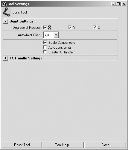
Open up the options for the Joint tool (Figure 11.1) found in the Skeleton menu. We are going to use the default settings in this chapter’s work, but here’s a list of all the options in the Joint Settings pane.
Note
You can alter any of these settings after a joint has been created.
![]() Degrees of Freedom dictates which rotations are active. Disabling X, Y, or Z will remove the ability to rotate around that axis. Disabling some axes can be done, for example, on an elbow joint, where you would want to rotate around one axis and not the others.
Degrees of Freedom dictates which rotations are active. Disabling X, Y, or Z will remove the ability to rotate around that axis. Disabling some axes can be done, for example, on an elbow joint, where you would want to rotate around one axis and not the others.
![]() Scale Compensate (when enabled) automatically scales other joints in the same skeletal hierarchy when you scale joints above them. The default setting for this option is enabled.
Scale Compensate (when enabled) automatically scales other joints in the same skeletal hierarchy when you scale joints above them. The default setting for this option is enabled.
![]() Auto Joint Limits lets Maya specify how far a joint can rotate around its axis.
Auto Joint Limits lets Maya specify how far a joint can rotate around its axis.
![]() Create IK Handle automatically adds IK (Inverse Kinematics; see Chapter 12) to your character’s joints as you create them. As tempting as this option might seem at first glance, it’s rarely a good idea to use it.
Create IK Handle automatically adds IK (Inverse Kinematics; see Chapter 12) to your character’s joints as you create them. As tempting as this option might seem at first glance, it’s rarely a good idea to use it.
![]() Auto Joint Orient determines how the axis on each joint will be set. In the default setting (xyz), X will always point down the bone. Y will attempt to point up, and Z will try to point out to the front (the Y and Z axes’ positions are determined more by the orientation of their child bones than the effect of this setting).
Auto Joint Orient determines how the axis on each joint will be set. In the default setting (xyz), X will always point down the bone. Y will attempt to point up, and Z will try to point out to the front (the Y and Z axes’ positions are determined more by the orientation of their child bones than the effect of this setting).
You can see the effect of the xyz Auto Joint Orient setting demonstrated in Figure 11.2. In this example, there are two joints, and in the center of each you can see the joint’s rotational axis: X pointing down the bone toward the next joint, Y pointing up, and Z pointing out to the front.
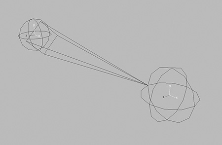
We will talk more about the rotational axis and joint orientation later in this chapter.
Tip
To show the selected object’s rotational pivot, go to Display > Component Display > Local Rotational Axis.
Now that we know a little more about the options available for joint creation, let’s continue on and build the skeletons that will animate our characters. We will work on Kila first.
Kila’s Skeletal Structure
For Kila we need an essentially standard skeleton to start us off. First we will create her limbs.
Load the file that contains all the LODs, Kila_LOD_Prep.mb.
Some joints may already exist in the scene; these were used back in Chapter 6 when we tested Kila’s deformation. Delete these for now; we want to construct this skeleton from scratch.
We don’t want to edit any of the geometry, so turn the display layer visibility off for the lower levels of detail, and set the highest LOD’s display type to Template.
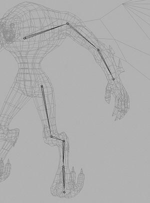
1. Switch to the front view and go to Skeleton > Joint Tool to begin building in the joints for Kila’s arm, starting with the clavicle, or collarbone (Figure 11.3). Then build joints for her leg, starting at the hip.
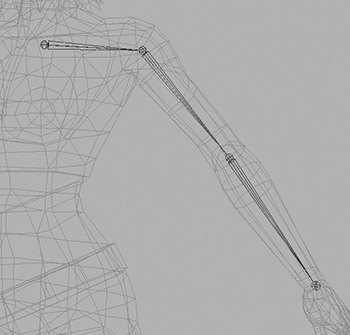
After placing each joint, you can manipulate its position by clicking on it with the middle mouse button. Press Enter to complete each chain. Make sure the joint chains for the arm and leg appear straight when you’re looking at them from the front.
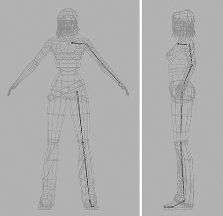
2. Next, using the top and side views, position all the joints of the arm and leg so that they lie down the center, or close to it, of the geometry (Figure 11.4).
Tip
If you need to move the joints after the chain is complete, press the Insert key. This allows you to move a joint without affecting others in the joint hierarchy.
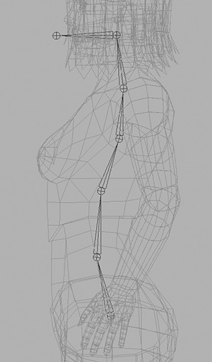
3. The main part of the spine is constructed from six joints, starting with the base joint located halfway between her navel and her crotch. The fifth joint in the chain should be at the base of her neck, leaving the sixth and final one to be positioned parallel to the neck but no higher than her mouth.
With the main spine done, create one additional joint out in front of her head, resting just outside her mouth.
You can see all seven of these joints in Figure 11.5.
4. You currently have three separate skeletons; now you will combine them into a single one. Select the clavicle joint and then the spine joint that exists just below it. Press P to parent them (Figure 11.6).
5. Parent the thighbone to the first, base joint of the spine (Figure 11.7).
6. The basic skeleton now exists for Kila’s left side. You still need to add the joints for her fingers, which should be parented to the wrist (Figure 11.8). Create four joints for each of the five fingers, and then parent each root joint to the wrist.
With these basic joints in place, we can now copy and mirror them to create Kila’s right side.
1. Open the Outliner, and Shift+click on the plus sign next to the joint hierarchy. This opens up the entire hierarchy as shown in Figure 11.9, left.
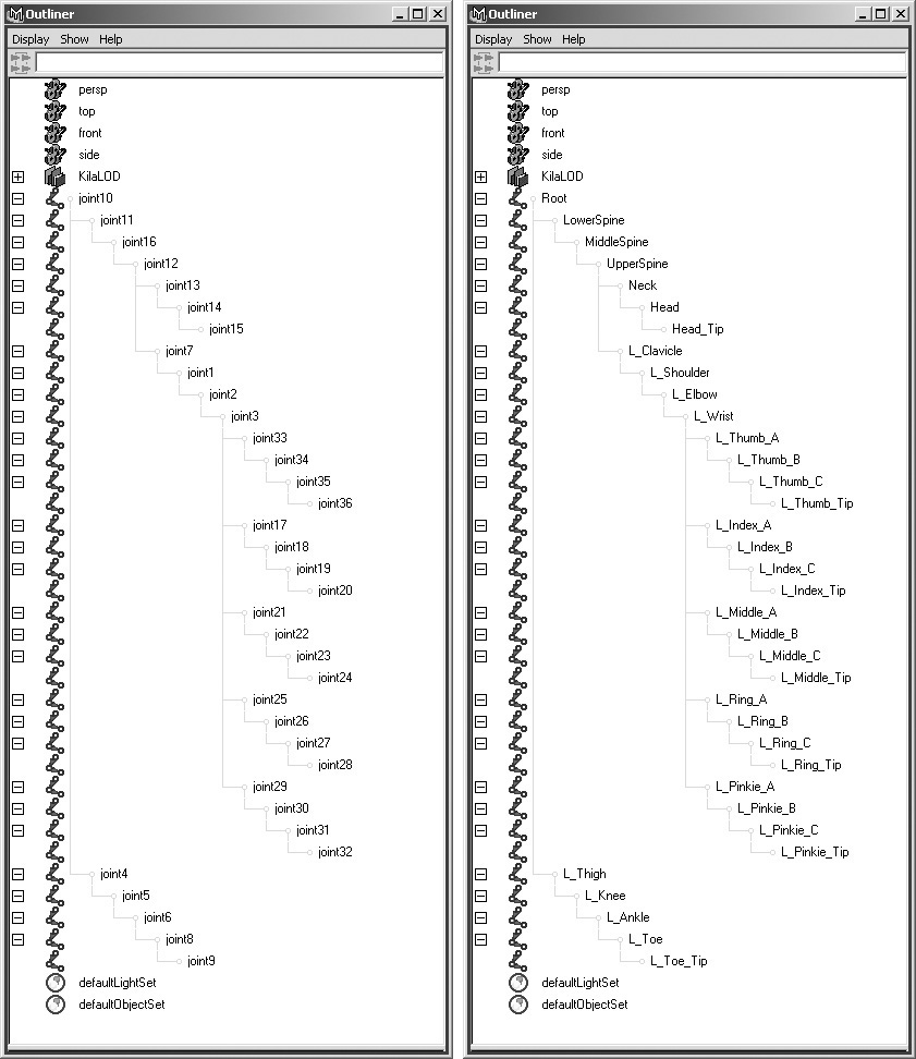
In the hierarchy’s current state, you can’t tell which joint is where, so let’s go in and manually rename them all. Call the very first joint Root, and put the prefix L_ in front of the names of all the left-side joints. Add _Tip at the end of the names of the joints at the very end. See how the new hierarchy looks in Figure 11.9, right.
2. Now select the L_Thigh joint. Go to Skeleton > Mirror Joint and open the options (Figure 11.10).
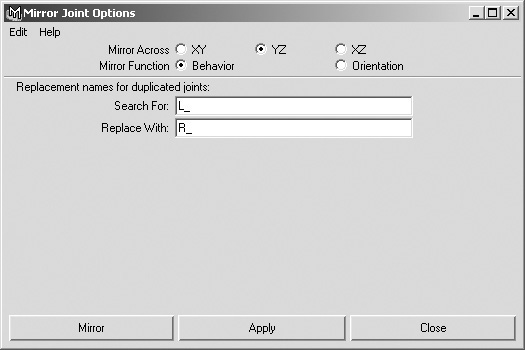
3. Set Mirror Across to YZ; this will mirror the joints from +X to –X. Leave Mirror Function set to Behavior. In Search For, type L_; and in Replace With, type R_. This renames all the mirrored joints beginning with L_ so they begin with R_.
Click Apply when you’re finished; you’ve now created the right leg.
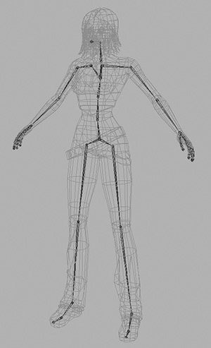
4. Select the clavicle and mirror it, using the same options, to create the right arm.
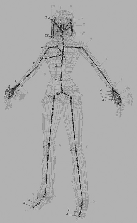
As you can see in Figure 11.11, Kila now has a basic skeleton. Save the file as Kila_Skeleton.mb.
Load the file Grae_LOD_Prep.mb, and prepare it by turning off all the display layers except the first one (Grae_5174). Set this level’s display type to Template.
Remove any joints that currently exist in the scene, except for the ones you created for the wings (and keep these hidden for now).
1. Use the Joint tool to create the left arm and leg joints (Figure 11.12). Remember to begin the arm from the clavicle.
Tip
Because of the size difference between our two characters, Grae’s joints may not be clearly visible, so adjust the display size of joints by going to Display > Joint Size.
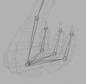
2. Grae has individual toes, unlike Kila, so create the joints that will animate these (Figure 11.13).
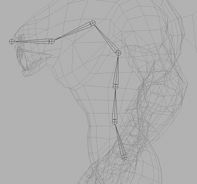
3. Next, implement the spine. Grae’s will be quite different from Kila’s, of course—try to follow the curve of his upper body as seen in Figure 11.14.
4. With Grae’s spine in place, parent the clavicle to the joint nearest to it on the spine, and parent the thigh joint to the root of the spine.
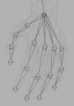
5. To complete the left side, build the joints into the hand. Keep in mind that Grae has fewer joints in each finger than Kila does (Figure 11.15).
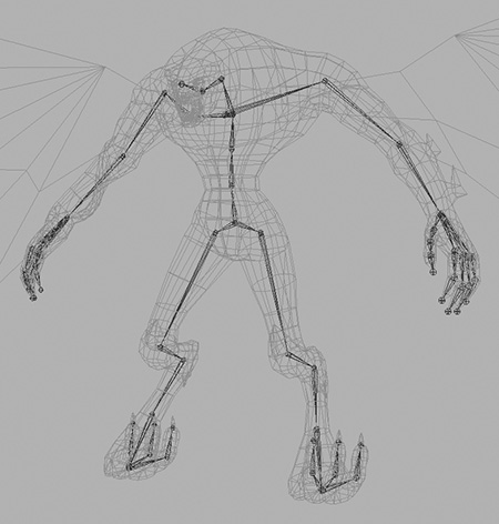
6. To complete the base skeleton for Grae, rename all the joints (remembering to use the L_ prefix and place _Tip after the names of the end joints—these will be on the fingers, toes, wings, and head). Then use the Mirror Joint tool to create his right side.
The base skeleton is complete; you can see it in Figure 11.16.
For both the basic skeletons that now exist inside each of our characters, we can improve on the way they animate by adding extra joints on top of the fundamental ones.
Additional Joints
Working with the fundamental skeleton is ideal for animating a character’s main body, but what about other areas such as the eyes, Grae’s wings, Kila’s hair, and even her chest? To make the character appear more realistic, these areas should animate, too.
Eyes
Kila and Grae’s eyes need the ability to move, so first we will create joints to animate them. Follow these steps for both characters, as their eyes will work the same.
1. Start by hiding all the geometry except for the eyes.
2. When we created the eye, we removed the back half because it wasn’t needed. For the eye to rotate convincingly, we need the joint to be in the center of the original sphere.
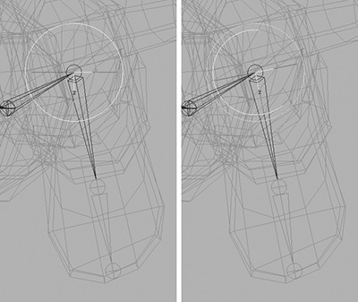
So create a single joint and, looking from the front, position it over the center of the eye (Figure 11.17, left).
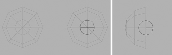
3. Switch to the side view, and move the joint to the very back of the eye geometry (Figure 11.17, right).
4. With the eye in position, rename it to L_Eye and parent it to the head joint (Figure 11.18, left).
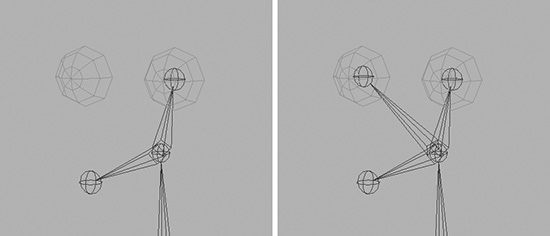
FIGURE 11.18 Parent the left eye joint to the head joint before mirroring it to create the right eye.
5. Use the Mirror Joint tool to copy the new eye across to create the right eye (Figure 11.18, right). This should automatically rename it R_Eye in the process.
That’s the eyes in position. We will look into adding more joints in the way of facial animation in Chapter 13.
Kila’s Chest
As Kila moves around, it would be nice to add a little bounce to her bosom, giving her a bit more life and making her seem more organic. We can approach this enhancement in two ways: using either joints rotations or translations to add animation.
If we use the translations method, we have freedom to move the joints anywhere in space. Also, the main pivot point will actually be inside each breast, meaning we are essentially picking each breast up and moving it around. Using rotations limits the movement to around the pivot point itself. This is ideal for rotational-based animation, on which the majority of the body is based. What you need to find out at this stage is how the joints are handled when they are exported and placed into the game. If the engine can only handle rotations, then the decision is made for you.
But which method is best? It depends on the area you are animating and what you need it to do; in this instance, both techniques will provide good results. Let’s take a look.
Open up the file named KilaChestTest.mb.
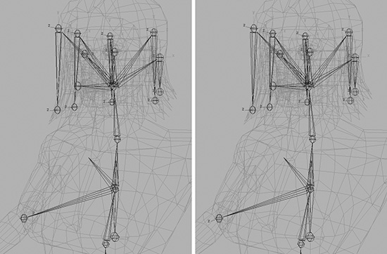
Press Play in the Time Slider, and you’ll notice that the movement of both breasts is almost identical, yet the one on the right is controlled via translations whereas the left side is controlled by the joints’ rotations. The only initial difference can be seen when you look from the side. As the chest rises, the breast controlled via rotations tilts upward as it rotates.
Look at the joint configuration for the two techniques in Figure 11.19. As you can see, the joints on the left, which control the breast via rotations, have to be quite far back, just past the spine in fact. Having the joints too close to the breast will cause it to tilt upward unnaturally as it rises and falls.
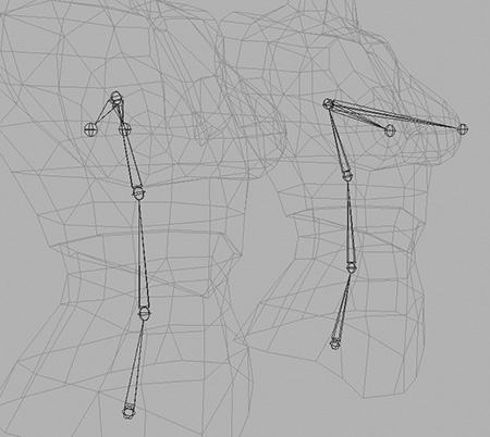
With the joints placed actually inside the breast, as shown in the torso on the right of Figure 11.19, controlling them with their translations will initially give you a good idea of how they will move—as well as giving you more freedom over where they move.
Using translations to manipulate your geometry will allow you to animate it through all three degrees of movement. With rotations, on the other hand, you are locked to the pivot point and so can only move the breast up and down and twist it. Using translations, however, lets you move it up, down, and in and out.
So for Kila, we opt for the translation method—but in other projects, make sure you check on which methods are possible for your game environment, and think first about what you want the area to do.
Kila’s Hair
Kila’s hair is quite long, so if it doesn’t have some movement it won’t look natural. Ideally, the hair would be controlled by an in-game physics engine, but for the purposes of this book we will add some joints to give it basic movement.
We could create lots of joints, giving us the freedom to do anything we want with the hair, but its current topology and associated joint restrictions mean we have to rely on fewer joints.
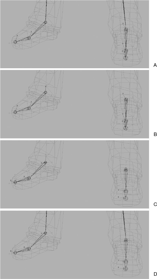
1. First, hide the main skeleton. Then, as demonstrated in Figure 11.20a, create five individual joints along the bottom of her hairdo.

Tip
If the geometry layer is set to Reference instead of Template, joints can be point-snapped to vertices, which will aid in their placement.
2. Because we want the hair to swing, using rotations is the best way to animate it. Duplicate the five joints you just created, and move them up to the pivot points from which the hair “hangs.” Halfway up the side of her head is an ideal position (Figure 11.20b).
3. Parent the lower joints to the upper ones (Figure 11.20c). Rename them all, adding _Tip after the names of the lower joints so that you will know these are end joints.
4. Unhide the main skeleton, and parent the hair joints to the head. This gives you the setup shown in Figure 11.20d.
We now have the ability to add some movement to her hair.
Grae’s Wings
Grae’s wings, like Kila’s hair, need the ability to move. You should already have a wing setup left over from Chapter 6. We can use that here, saving us the effort of creating a new one.
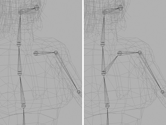
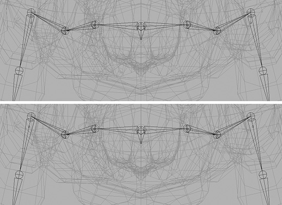
First we need to address the wings’ ability to open and close. With the current joint hierarchy we can’t do this (Figure 11.21, left). The single joint at the wrist rotates all the fingers of the wing; we need to be able to rotate these individually.
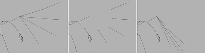
1. Select the middle joint of each wing finger, and go to Edit > Unparent (Figure 11.21, middle).
2. Now select the knuckle joint to which they were originally parented, and duplicate it four times. Call these duplicates L_Wing_Finger01_Base, L_Wing_Finger02_Base, L_Wing_Finger02_Base, and L_Wing_Finger04_Base.
3. Parent these new joints to the one from which they were duplicated, L_Wing_Wrist.
4. Now parent the ends of the wing fingers to the new joints. So L_Wing_Finger01 will be parented to L_Wing_Finger01_Base, and so forth. In effect, the wing will look no different than when we began.
As you can see in Figure 11.21, right, we can now open and close the wing by using the new joints we’ve created.
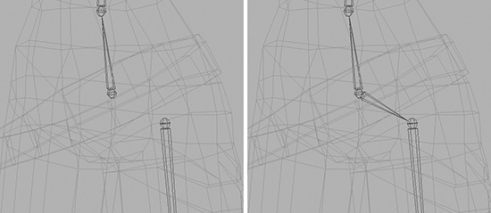
Now that the wing is easier to pose, we can go about attaching it to the main skeleton and mirroring it for the wing on the right.
1. To start, simply parent the wing to the upper spine joint—the same one to which the clavicles were parented (Figure 11.22, middle).
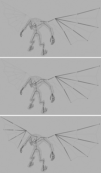
2. To create the wing on the right, select the first joint belonging to the existing wing and use the Mirror Joint tool (Figure 11.22, bottom).
Joint Cleanup
The principal skeletons for Kila and Grae are now complete, so let’s find out how many joints make up each one. In this case, I have made this easy for you; the number of joints in the scene does not match the number that will be used in the game. All of the end joints are there merely as a visual aid; the actual geometry will not use them to move.
Note
You’ll want to double-check this with the relevant programmer; it may be that your game engine does need these end joints.
Contained in the GCDM shelf is a button labeled jntCnt. Running this will give you an accurate joint count. It will not, however, include any of the end joints (such as the eyes), so you will have to add these to the count.
Using the jntCnt tool, we can see that Kila uses 57 joints, plus another 4 for her eyes and chest, bringing the count up to 61. Grae uses 66, plus 2 for his eyes, making the total 68.
In the next section, we will need to check how the skeleton will move—or, more accurately, rotate.
Depending on how you constructed the skeleton, there may be some values in the rotation attributes. Because the majority of the skeleton is controlled by its rotations, it’s vital that these are zeroed out before checking the rotational axes. Having them all at zero will simplify animation and control.
Before we continue to the next task, quickly select all the joints and freeze the transforms, making sure to freeze only the rotations.
Checking the Rotational Axis
One of the most important stages in character rigging, particularly in Maya, is to check the rotational axes. The way a joint rotates depends on how the axis is aligned. This is particularly important when you are using joint chains as we have done in Kila and Grae.
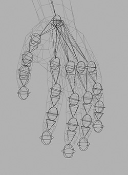
Look at Figure 11.23, left. Here we have our current hand for Kila, which looks fine. To get the fingers to bend and make a fist, we would select the root of each finger, then its hierarchy, and do a global rotation around the Z axis. Figure 11.23, right, shows the result. Because all of the rotational axes are out of line at this point, the fingers are all bending in random directions.
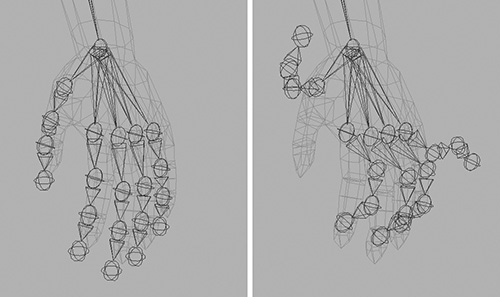
FIGURE 11.23 Rotating the fingers around the Z axis demonstrates that the rotational axes are not correctly aligned.
You’ll find this misalignment in a number of areas around the skeleton as it is currently constructed, so let’s fix them.
This gives us the opportunity to look at two more of the tools located on the GCDM shelf: rsJnt and orJnt.
![]() The rsJnt tool will reset a joint’s axis to match the one above it in the hierarchy. If no joint exists above the joint being reset, rsJnt will match the world axis.
The rsJnt tool will reset a joint’s axis to match the one above it in the hierarchy. If no joint exists above the joint being reset, rsJnt will match the world axis.
![]() The orJnt tool attempts to reorient each joint using the default xyz setting (in this case, X pointing down the bone, with Y and Z perpendicular to it).
The orJnt tool attempts to reorient each joint using the default xyz setting (in this case, X pointing down the bone, with Y and Z perpendicular to it).
Note
Maya does have its own tool for reorienting joints (Skeleton > Orient Joint). I’ve found, however, that this tool doesn’t operate as I’d expect when more than one joint is selected. Feel free to use the Maya command if you prefer.
1. Select the root of Kila’s skeleton. Then select the rest of the joints below it by going to Edit > Select Hierarchy.
2. With the joints now selected, go to Display > Component Display > Local Rotation Axis. As you can see in Figure 11.24, right, each joint’s axis is now visible.
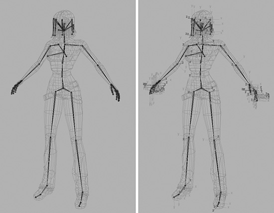
Now that we can see each axis, we can realign them.
3. To start, reset the spine joints. Select the main root joint and continue selecting your way up the spine, right up to the Head_Tip joint. Make sure you select the joints in order.
Tip
It can be a little confusing having all the rotational axes displayed at once. I recommend hiding the ones you are not currently working on. Select a joint and go to Display > Component Display > Local Rotation Axis. You can go a step further by hiding the inactive joints, too, but be warned that hiding one will also hide all the ones beneath it in the hierarchy.
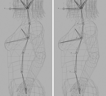
4. Figure 11.25, left, shows the current orientation of the axes. Click rsJnt, and these will be reset as seen in Figure 11.25, right—all nice and neat, with Z pointing forward.
5. Next, perform the same resetting process on the breast, eye, and hair joints (Figure 11.26).
Normally, a joint’s rotation should match the orientation of the joint itself, with one axis pointing directly down the bone. We are ignoring this principle for the breast, eye, and hair joints, however, because we want the rotations to match Maya’s world pivot. In Chapter 12, we will be assigning rigging controls to these joints, so having the axes at this default state will make them easier to control.
That’s the center of the body complete, now, so let’s proceed to the arms and hands.
To orient the arms correctly, we first need to temporarily reset the clavicles. We do this because the orientation of the arm joints will be based on their parent joints. If we simply fixed the clavicle without resetting, the shoulder’s Y axis would not point directly up, and the arm’s rotation would be off. Resetting the clavicle will allow the shoulders, and then the rest of the arm’s axes, to orient correctly.
1. Select the clavicle joints and click on the rsJnt button.
2. Select the shoulder and elbow joints; this time click on the orJnt button.
3. Because the wrist joint has lots of children, we can’t tell it to adjust the axis so that X points down one bone toward the next one. In this case, our hand is oriented the same as the upper arm, so we can use the rsJnt tool which will copy the previous joint’s orientation.
You can see the arm orientations in Figure 11.27.
Note
Think about how you want the hand to bend before you jump in and reset the orientation. If the alignment process described here is not going to work, then you will have to edit the rotational axis manually, which we will look into shortly.
4. For the fingers, simply select each joint and press orJnt (Figure 11.28, middle).
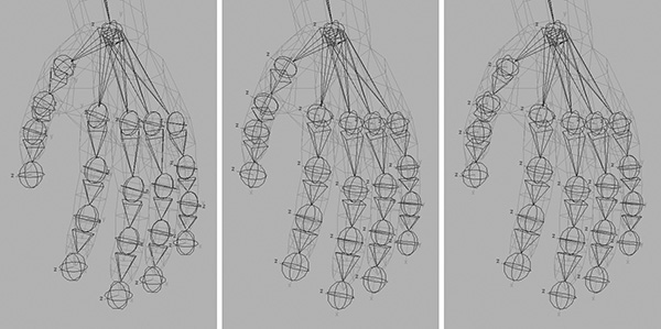
Now the thumb will have the same orientation as the fingers, but if you rotate your own thumb you’ll notice it works on a different axis. To rectify this, the GCDM shelf has another button labeled rot45. This tool will rotate the joint’s rotational pivot around the X axis at 45-unit intervals.
5. On the left hand, select the thumb joints, and press the rot45 button seven times (Figure 11.28, right).
6. For the right hand, you only need to press this once because the orientations are mirrored.
Tip
Make sure to double-check against your own hand to verify the proper effect is achieved, particularly for the thumb.
The last joints to tackle are in the legs. Starting from the hip, select each joint and press orJnt. As you can see in Figure 11.29, this works well on the legs. The feet, however, are at an angle. We want the pivots to be flat (an axis flat and parallel relative to the grid) while also being aligned with the foot; otherwise, when we rotate the feet, they will skew off to one side.
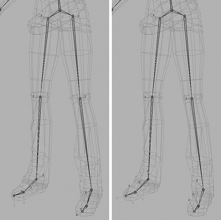
We could try resetting the ankle joints, but this won’t work; they will only inherit the previous joint’s pivot. So what we do is this:
1. Select the ankle joints and unparent them from the knees (Edit > Unparent); see Figure 11.30b.
2. Now reset the ankle joints. They will inherit the world pivot, making them nice and flat.
3. With the ankles set, you can select the rest of the foot joints and run orJnt on them (Figure 11.30c).
4. Parent the ankles back to the knees (Figure 11.30d).
The feet aren’t finished yet—we still need to fine-tune them. Look from the top view, as seen in Figure 11.31, top. Although the axes are flat, which is how we want them, they don’t match the orientation of the foot. Each foot points slightly outward, whereas the axis is pointing dead ahead. We need the axis to match that shown in Figure 11.31, bottom.
5. Go up to the status line and select the Select By Component Type button, the second button from the left in Figure 11.32.

You are now in Component mode, but you still need to tell Maya what components you want to edit.
6. Right-click on the question mark toward the right end of the status line (Figure 11.32). On the menu that appears, select Local Rotation Axis.
7. Now physically select the ankles’ rotation axes and rotate them to match the joints, as demonstrated in Figure 11.33. Make sure to restrict your rotation to the Y axis, so that X remains flat relative to the ground/grid.
8. Press F8 when you are done to return to Object mode.
With the rotational axes cleaned up, the skeleton is complete (Figure 11.34). Save your work, updating the Kila_Skeleton.mb file.
Grae’s skeleton can be adjusted in exactly the same way as Kila’s. Go ahead and work on this next, updating the file Grae_Skeleton.mb.
Repositioning the Characters
Before we move on to Chapter 12, there is one final thing to check in our characters so far: their overall position in Maya.
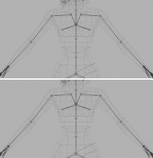
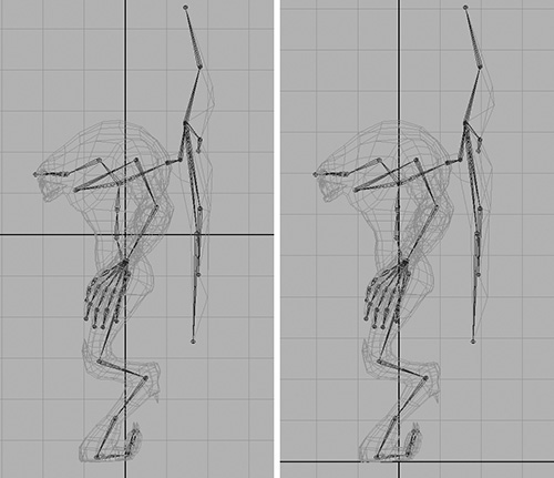
Switch to the side view and make sure the grid is enabled (Show > Grid). You will see that the characters are not aligned with the world correctly (the left panels of Figures 11.35 and 11.36). The two thick black lines of the grid show the world’s root; the horizontal one is our floor.
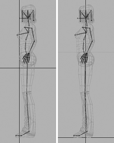
Select KilaLOD and Root in the Outliner, moving them up the Y axis and along the Z axis until their feet rest on the horizontal line, as seen in Figure 11.35, right. Do the same for Grae: Select GraeLOD and Root in the Outliner then move them up as seen in Figure 11.36, right.
When finished, freeze the transforms on their LOD groups, making sure you only have Translate selected.
Summary
The first stage of character rigging for Kila and Grae is complete. We have created base skeletons and adjusted the rotational axes to correct orientations, allowing the skeletons to animate correctly. Next we will add controls to the skeletons, making it easier to pose and animate the characters.