Once you have completed all the implementation tasks discussed to this point in the book, the focus begins to shift away from planning and implementation to operations—ensuring that the environment is available and that users are able to work without difficulty. Although most Terminal Server environments continue to be managed by the same people involved in the implementation, this is not always the case, and a distinction should be made between the role of the operator and that of the administrator. Typically an administrator is responsible for security and for planning and coordinating updates to the environment, while an operator is responsible for monitoring the day-to-day stability of the environment, ensuring that the system runs smoothly and provides maximum uptime to the end user.
In most small to medium deployments, the roles of an administrator and an operator are one and the same, but in larger organizations, either the role of the operator is completely split off in a separate position, or the responsibilities of the operations role are divided between the administrators and the first-level help desk support staff.
NOTE:
The role of an operator has its roots in the early mainframe days, when a system operator (sysop) was basically available 24×7 to ensure that the computer system remained operational. Routine tasks such as tape rotations for backups (these were large tapes), loading of punch-card code into the system, and print job collation and management were just some of the common duties an operator was required to perform. In addition, he or she was available in case of mainframe issues that required immediate attention.
Regardless of how the tasks are divided, someone is responsible for performing periodic maintenance and management of the environment in addition to planning and implementing the changes necessary for future growth requirements. The purpose of this chapter is to discuss some of the common tools and techniques used to manage an environment once it is in production. The chapter has been broken down into the following sections:
Load-Balancing Configuration—. On a number of occasions in the book I discuss use of software tools such as Microsoft’s Network Load Balancing or Citrix Load Manager to provide load-balancing capabilities in your deployment. Load balancing not only provides a transparent way of distributing your user sessions across all the Terminal Servers in your environment, but it also can simplify maintenance by letting an administrator remove a server from the load-balancing cluster without having to change the client-side settings. Proper techniques can ensure that a server is taken offline with zero impact to the end users.
Server Cloning—. Besides load balancing, another method of providing redundancy in the environment and maximizing stability is to employ the technique of server cloning. When a Terminal Server/MetaFrame server has been properly configured and thoroughly tested, using server cloning to replicate that configuration can help ensure that the servers in the environment maintain a consistent configuration and minimize the chances of one configuration misbehaving due to differences in the installation and configuration.
NOTE:
While some people argue that cloning can exaggerate issues by allowing a misconfigured server to be replicated across all hardware, I feel this is a concern only if the environment was not properly set up and tested in the first place. Proper testing helps ensure that the configuration deployed is correct and behaving as expected.
Server Health Monitoring—. Using integrated tools such as the Resource Manager, third-party tools or utilities from the Resource Kit, or even Performance Monitor, the operator takes on the role of proactively monitoring the status of all Terminal Servers so potential problems can be flagged early and resolved before they cause system degradation or unscheduled downtime. This task is extremely important for any organization that must guarantee a minimum level of service to its customers. Proactive server monitoring can also alert you to the need to plan for eventual expansion of the environment.
In Chapter 8, “Server Installation and Management Planning,” I discussed Terminal Services load balancing using the Network Load Balancing functionality available in Windows 2000 (Advanced Server or Datacenter Server) and with all versions of Windows Server 2003. I also talked about the Load Manager component of MetaFrame Presentation Server, Advanced and Enterprise Editions. In this section I briefly discuss configuration and use of these tools.
In Chapter 8 I provided an overview of the features and functionality of the Microsoft Network Load Balancing (NLB) service and how it provides a means of introducing scalability to a Terminal Server environment. NLB is a component of Windows Clustering that allows multiple servers to provide TCP/IP-based services to users through one or more “clustered” IP addresses. The servers are “grouped” together and operate conceptually as a single entity. NLB was developed primarily to provide redundancy for Web-based services such as Web or FTP servers, but the same functionality can be used in a Terminal Server environment.
When configuring NLB to function with Terminal Services, there are three main tasks that must be performed:
Verify the appropriate hardware configuration for your environment.
Configure the Terminal Servers in the environment to operate using NLB.
Configure the Terminal Services clients to connect to the cluster host name or IP address instead of a specific server name.
While Microsoft supports use of NLB on servers with only a single network adapter, the recommended configuration calls for two network adapters to be present. When a single network card is used it must handle both inbound cluster traffic and intra-host communications, while the same tasks can each be assigned to their own network card when two are present.
The number of network cards in the server dictate the operation mode of the cluster. The operation mode determines how the cluster interfaces with the network adapter(s) on the server and what type of MAC (media access control) addressing is assigned. Two modes are available:
Unicast mode—. This is the default configuration for an NLB cluster; selecting this option causes the MAC address for the cluster to overwrite the physical MAC address assigned to the network card on each server in the cluster. Because all hosts in the cluster share the same MAC address, in a single network interface card (NIC) deployment, no intra-host communications other than NLB-related communications are possible.
Multicast mode—. When this mode is selected the virtual MAC address of the cluster is assigned to each server’s network card, but each card retains its own physical MAC address. In an NLB deployment with only single network cards, intra-host communications are still possible when multicast mode is enabled.
Multicast mode may not be supported in your network environment, depending on the router hardware in place. The router hardware must support mapping the single IP address of the cluster to the multicast MAC address, or the multicast mode cannot be used. Static address resolution protocol (ARP) entries may also be required on routers that do not accept ARP responses that give a multicast MAC address for a single IP address.
In a single network card configuration, the inability to support intra-host communications means that the NLB Manager tool provided with Windows Server 2003 cannot be used to manage operation of the cluster unless it is run from a host outside the cluster. This invariably causes confusion for administrators who are new to the operating behavior of NLB.
Restrictions on the management of one server from another are not limited to only the NLB Manager. Any type of management task attempted from one server to another within the cluster will not function properly, which can cause significant management issues, since a common practice for Terminal Server administrators is to connect to one Terminal Server in the environment and perform most of the management tasks remotely against all other Terminal Servers.
If you plan to employ NLB as the load-balancing solution for your Terminal Server deployment, I recommend using dual network cards. Most servers purchased today include dual network adapters in their base configuration, so I find this is rarely a cause for concern. In my installation and configuration example in this chapter, I assume you’re deploying NLB in a dual network adapter configuration.
TIP:
When using NLB, a user’s Terminal Server session information is not simultaneously maintained across multiple servers, as the term clustering might suggest. If a user is active on a server that fails, their session and any information currently open within that session are lost. If the user reconnects, they are automatically directed to an alternate server still active in the cluster.
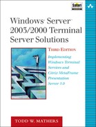
No explicit installation steps are required to make NLB available. On a Windows server that supports NLB, the necessary NLB driver option is visible under the Local Area Connect properties, as shown in Figure 22.1. If an NLB option is not visible, you are not running a version of Windows that supports NLB. Enabling and configuring the properties for the driver dictate how the cluster behaves.
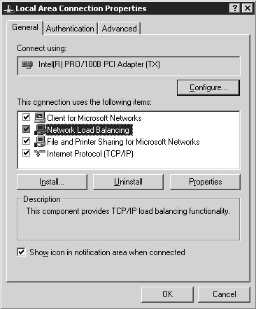
Figure 22.1. NLB is available as a special network service on all supported versions of Windows and is supported only with the TCP/IP protocol.
NLB is enabled and the settings configured in one of two ways:
By selecting the properties for the NLB driver on each server participating in the cluster. This is the only configuration option supported by Windows 2000 Server.
By using the Network Load Balancing Manager tool provided as part of Windows Server 2003.
In a Windows 2000 Server environment, you have little choice but to employ the manual method of configuration on a server-by-server basis; Figure 22.2 shows the main property page for NLB on a Windows 2000 Advanced Server. In this section I demonstrate configuring a cluster using the Windows Server 2003 NLB, but I include the associated position within properties of the NLB driver so you can find similar settings in a Windows 2000 deployment.
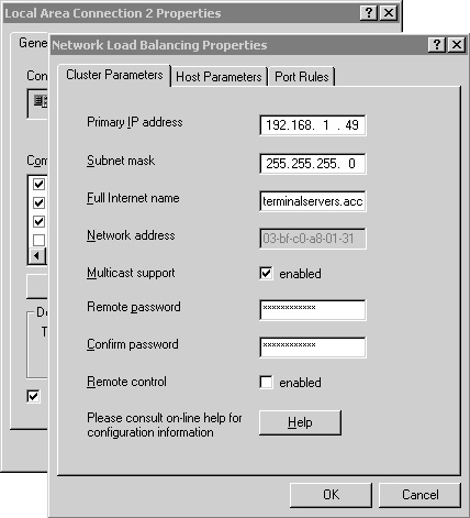
Figure 22.2. NLB in a Windows 2000 environment must be configured through the properties page for the NLB driver.
TIP:
Always ensure that the network adapter to be used as the NLB cluster interface has a static IP address assigned. You cannot designate an adapter that was configured using DHCP for use in an NLB cluster.
Also, I do not recommend that you perform the NLB Manager installation and configuration when directly connected to the host via an RDP or ICA connection. If you do so, when the NLB component is configured you may be disconnected from the server. It is always preferable to perform configuration from a remote host using the NLB Manager or by running the NLB Manager from the physical console session directly on the host.
NLB is configured on a Windows 2003 Terminal Server as follows:
Begin by launching the NLB Manager from Administrative Tools on the Start menu.
If there are any existing clusters that have been managed from this host, they appear in the main program window; otherwise this window is empty.
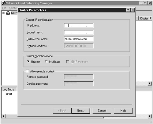
Select New from the Cluster menu to bring up the first page of the configuration wizard, labeled Cluster Parameters (Figure 22.3).
Begin by providing the IP address to be assigned to the cluster. Any Terminal Server client requests directed to this IP will be serviced by the cluster. Provide the IP address, the corresponding network mask, and the fully qualified domain name of the cluster. A name that I commonly use is terminalservers.<domain name>. For example, I might use terminalservers.nrtestdom.com within my Noisy River test domain. The network address (also known as the MAC address) cannot be manually modified, but if you change the cluster operation mode from unicast to multicast, you see the address change. When using a dual network adapter configuration, I recommend selecting the unicast mode.
Enabling the Allow Remote Control option allows the cluster to be remotely managed using the command line tool. Enabling this option can pose a security risk, and for this reason I recommend that it not be enabled. Managing the cluster using the NLB Manager does not require that this option be enabled. Once you have completed entering the desired information, click Next to continue.
The next dialog box prompts you to enter any additional IP addresses that you want to associate with this NLB cluster. This allows you to have multiple addresses all directed to the same cluster. Multiple addresses may be used if you’re consolidating multiple separate environments under one NLB cluster. If you want to support multiple addresses, you can enter them now. To do so, click the Add button and then enter the address and subnet mask. Repeat this for each address you want to add. When finished, click Next to continue.
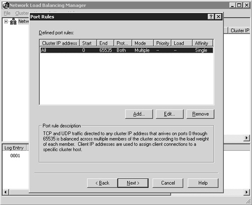
Next you’re presented with the Port Rules dialog box, shown in Figure 22.4. The default rule is automatically applied, and the associated description for that rule is shown in the Port Rule Description field near the bottom of the dialog box. When you use this default configuration, all the Terminal Servers in the cluster automatically load-balance RDP client requests.
You can trim down the range of ports that are monitored to include only the RDP client port. By default this port number is TCP port 3389. You can modify the existing default port rule by clicking the Edit button; the Add/Edit Port Rule window appears. Figure 22.5 shows the settings to configure the cluster to monitor the RDP port 3389, and as a result load-balance Terminal Server client sessions across the cluster.
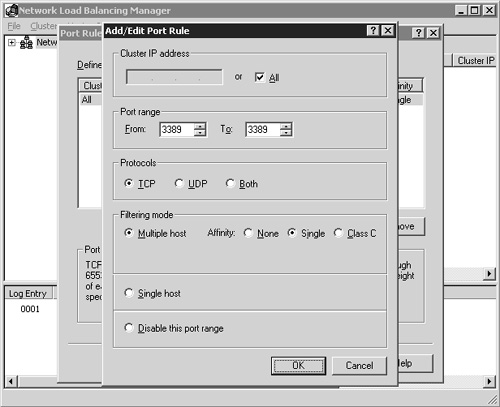
Figure 22.5. You can modify the default port rule to apply only to RDP client connections if desired.
The port range defines only the listening port for the hosts in the cluster, so only 3389 needs to be defined. TCP is also the only protocol that needs to be selected, since RDP connections are established using TCP, not UDP. The filtering mode has three options, with the default mode being Multiple Host. This specifies that multiple hosts in the cluster will service this port rule. This is the mode you choose when configuring load balancing for Terminal Services. With this selection, you have three client affinity options from which to choose. Affinity controls how servers in the cluster manage multiple connection requests from the same client. The details of each type are provided in Chapter 8 and in summary are as follows:
None—. Allows multiple connections from the same client to be serviced by different cluster members. If a user connects to the cluster, logs off, and then reconnects an hour later, he or she is not necessarily directed to the same server. This can pose a problem if a user has a disconnected session on a server in the cluster. With affinity None, there is no guarantee that the user will reconnect to that disconnected session unless the Session Directory feature of Windows Server 2003 is also used. Windows 2000 has no mechanism for automatically associating a client with a disconnected session in the cluster. Microsoft recommends that Terminal Servers in a cluster with an affinity of None be configured so that disconnected sessions are terminated and not maintained on the server, thus helping to prevent sessions from remaining unclaimed and consuming server resources.
Single—. Specifies that all connection requests from the same client IP address are always serviced by the same host (at least until the next cluster convergence). This is the default configuration and, when implemented, increases the likelihood that a user will reconnect to a disconnected session on a server in the cluster. For this to be successful, the user must connect from a client with the same client IP address as the one that originally initiated the connection.
Class C—. Similar to Single affinity, except that instead of directing a single IP address to the same server, Class C affinity directs an entire Class C address range to the same server. This option is best suited for Internet-based connects that are typically distributed across a wide range of Class C networks. Class C affinity should not be selected when servicing local area network users, because they likely will all be from the same Class C network, resulting in all connects being serviced by a single host in the cluster.
Besides the Multiple Host mode the Single Host filtering mode is available. The Single Host option specifies that a single host in the cluster will be selected to service this port rule. The same server manages all requests for this port until it fails or convergence selects a new server to take over this role. The Single Host option is not appropriate for most Terminal Server–based NLB implementations.
After defining the appropriate port settings, click OK to close the dialog box and return to the Port Rules window. Once you have defined the desired port rules, click Next to continue with the configuration
You now see the Connect dialog box, which prompts you to provide the name of a host in the cluster to which you will apply these configuration choices. You can provide the host name, a fully qualified domain name, or an IP address. After typing the desired server information, click the Connect button to establish the connection and return a list of all valid interfaces on the target server. Figure 22.6 lists the available interfaces on my first host server. Once I’ve selected the desired interface to be associated with the cluster, I can highlight it and click Next to continue. If you’re connecting to a remote server, you cannot select the interface on which you are connected to be configured for load balancing. You also cannot select any interface that may have been configured using DHCP instead of static IP mapping. NLB requires static IP addresses to be set.
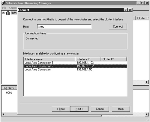
Figure 22.6. The Connect dialog box is where you select the host and an available interface on that host to configure the new cluster.
NOTE:
If you select an interface enabled using DHCP, the NLB Manager does not always warn you that this is an issue, and as a result, lets you complete creation of the cluster. If this happens, the cluster node can enter what appears to be an undefined state where the interface is neither active nor accessible in the cluster. If this occurs, the most effective way I’ve found to recover is to reboot the host machine and run the NLB Manager from a console session to remove the offending host. You may have to remove the cluster and restart the process if the problem is not corrected by this method.
After highlighting the desired interface, click Next to continue to the Host Parameters dialog box. This is where you verify that the interface information is correct. Figure 22.7 shows an example of how this screen appears. The first option is the Priority identifier, which is used to uniquely tag the host servers in the cluster. Ensure that this number is unique for each host in the cluster.
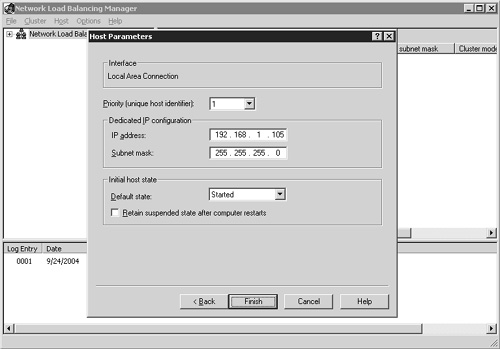
The next field is Dedicated IP Configuration, which must contain a static IP address. If this field appears blank, either you chose an IP address that is configured via DHCP or the network adapter interface is somehow corrupted. Do not proceed under these circumstances. Either cancel the configuration or click the Back button and correct the network adapter selection.
The Initial Host State field determines how the host starts. The default is Started, which means when the server is booted it automatically joins the cluster. The Stopped setting boots the host computer without joining the cluster; the server operates as a standalone machine. The Suspend State setting starts the server in the same configuration as if it were stopped, but if the “Retain suspended state after computer restarts” setting is not selected, the next time the server boots, it comes up in Started mode instead of being suspended again.
After the desired settings are configured, click the Finish button to complete NLB configuration. You are then returned to the main NLB Manager window, where you see the log entries generated in the lower half of the window as the NLB cluster is created.
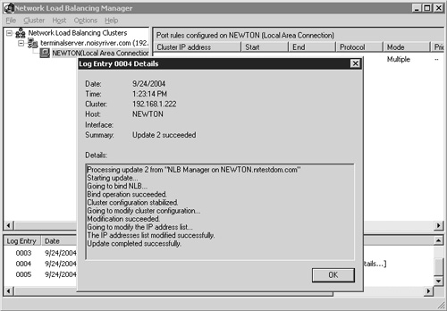
Once the NLB cluster creation has completed, the host name appears in green under the cluster name and you can see a log entry stating that the update was successful. You can double-click this entry to see details of the log entry (Figure 22.8). At this point the cluster is operational, so you are ready to test connectivity to verify that the cluster is working properly.
Testing connectivity from an RDP client to a load-balanced Terminal Server cluster is straightforward. All you have to do is launch the Remote Desktop Connection client and then provide the host name or IP address of the cluster. You should then be presented with a logon screen for a server in the cluster. By testing two or three simultaneous connections from different clients, you can see the load balancing as it spreads users across the available servers.
TIP:
Remember, if you configured your cluster to operate with Single affinity, the same client IP address automatically connects to the same host in the cluster until a condition within the cluster causes the convergence operation to initiate. Attempting to establish multiple connections from the same client machine to the cluster results in your continuously connecting to the same server. You are not divided among the available servers in the cluster.
In your production environment you may have a situation where you have multiple servers available, but some are more powerful and so can handle a larger number of concurrent sessions than other servers in the cluster. Once a server has been added to a cluster, you can adjust the load weighting of that host in order to boost its responsiveness to new client connection requests. Using this method you can designate servers that will take a proportionally higher number of client connections than other servers.
The Load Weight options are accessed by right-clicking the host within the NLB Manager and selecting Host Properties. From here, click the Port Rules tab and then edit your defined port rule that pertains to your Terminal Server connections. New options appear in the Filtering Mode section of the dialog box, as shown in Figure 22.9. The Load Weight options are now available, and the default value of 50 can be changed by clicking the Equal check box.
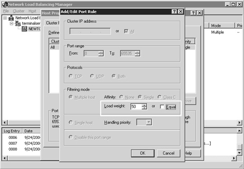
The load weight is a relative factor that can be set to any value between 0 and 100. When set to 0, a host does not accept any connection requests. The default value is 50, and by adjusting this up or down, you can increase or decrease the percentage of connections the host accepts in comparison to other hosts in the cluster.
TIP:
Network load balancing is based solely on network connections and not on heuristic calculations derived from processor utilization, memory utilization, or any other system factor. This means that if a server within the cluster is running in a degraded state, it can continue to attempt to process new client connections, even though another server in the cluster may have the capacity available to better handle the request.
When a connect request is made to the cluster, all Terminal Servers in the cluster receive the incoming request, and based on the distribution algorithm, one client accepts the connection request while all others discard it. Distribution is coordinated between the cluster members through the periodic exchange of heartbeat messages. When a new host is added or removed or fails to respond to a set number of heartbeat messages, the cluster enters a state known as convergence. During convergence, cluster membership is verified and the client load is redistributed accordingly. During this time, all cluster connections for the available hosts are serviced, but any requests destined for a failed host continue to fail until convergence is complete and an alternate host is selected to handle those requests. The default heartbeat interval is one second, and the threshold for missed heartbeats is five seconds. Both values can be modified by editing the following registry keys on all cluster members. Under the key HKEY_LOCAL_MACHINESYSTEMCurrentControlSetServicesWLBSParameters you find these values:
Often administrators find that they need to schedule taking a server offline for maintenance. While many environments have a single shift of workers and a window of time every evening when administrators can plan to make changes, some organizations have multiple shifts operating continuously, leaving no real time window when the server can be “forcefully” taken offline. Instead, the server must be configured so it continues to service existing requests while preventing new requests from being added to the server.
This is achieved within NLB using a technique called drainstopping. When this feature is enabled, hosts in the cluster stop accepting new connections but allow existing connections to function normally. Eventually all the active users log off, at which point the server automatically changes its state from Drainstop to Stop. You can stop connections immediately by issuing the Stop command, or you can cancel drainstop mode by issuing the Start command.
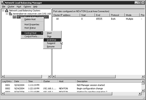
Drainstopping can be activated either at the host level or at the cluster level. When enabled at the cluster level, the drainstop rule applies to all servers in the cluster. You can enable drainstopping by clicking the host or cluster name and selecting the Control Host context menu. Five options are displayed, as shown in Figure 22.10.
In Chapter 8, I also discussed the load management features of MetaFrame Presentation Server that are included with the Advanced and Enterprise editions of the product. Unlike Microsoft Network Load Balancing, which is an additional Windows service that must be installed and extensively configured before it can be used, Citrix Load Manager installs as part of the above-mentioned MPS editions and is preconfigured and ready to use with no special configuration by an administrator.
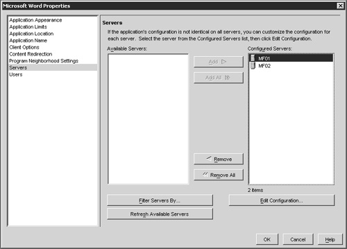
In Chapter 21, “Application Integration,” I demonstrated how to publish an application and explained how the process of publishing an application on more than one MetaFrame server would automatically enable it for load balancing. Figure 22.11 illustrates how easy it is to load balance the published application Microsoft Word across multiple MetaFrame servers. In this figure, the published application is being configured to run on both the MF01 and MF02 servers. Any minor variations in the installation location of Microsoft Word would be adjusted from the Edit Configuration button, but otherwise adding the servers to the Configured Servers list and clicking OK are all that is required to enable basic load balancing.
Citrix Load Manager is an integrated part of the published application concept of MetaFrame. If an application is being published, then the application is automatically available for load balancing simply by publishing it on more than one MetaFrame server in a farm.
TIP:
In order to load balance a published application across two or more servers, both must belong to the same server farm. Cross-farm load balancing is not supported.
MetaFrame’s load manager comes preconfigured, and for most simple installations, will not even have to be adjusted. Administrators can simply publish the desired applications and watch users load balance across the available MetaFrame servers. In larger or more complicated application publishing scenarios, an administrator will likely want to make minor adjustments to the load manager’s behavior to better reflect the desired load distribution in the environment. In order to do this you will need to understand the purpose of a load evaluator.
From within the Management Console for MetaFrame Presentation Server, you will see that there is an object for load management called Load Evaluators. Clicking this you will see that two load evaluators currently exist and are called Advanced and Default (Figure 22.12). These are the two evaluators that are included by default for use with Load Management.
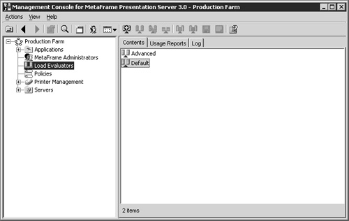
A load evaluator is simply a set of rules that dictates how a numeric load value is calculated for an object. The resulting numeric value for that object is then compared with the numeric values from other objects of the same type in order to determine which instance is “least loaded.” When load balancing, the least-loaded object is chosen to satisfy the connection request. A simple example will help to illustrate this.
A user is attempting to connect to the Microsoft Word published application and has initiated the connection from her MPS client. The client contacts the farm and requests the IP address of the least-loaded server that is publishing Word. The farm then requests the current load from all servers publishing Word and determines based on the value returned, which server will satisfy that user’s request. The IP address for that server is returned to the user, and she proceeds to log on. The actual load value that each server returns to the farm is determined by the load evaluator that is associated with the published application, in this case Microsoft Word.
In order for any object to load balance, it must have an associated load evaluator. When a MetaFrame server is installed, the server object is automatically assigned the Default load evaluator. This is the evaluator used by each application that is published on that server unless otherwise specified. A load evaluator is always assigned to a server, and can optionally be assigned to individual applications on a per server basis. If an application has an evaluator assigned, it will override any settings within the server’s evaluator.
Returning to the two evaluators that are included with MetaFrame, Figure 22.13 shows the specific configuration settings for the Default evaluator. The Default load evaluator is configured so that it will return a load value of 100 percent when there are 100 users logged on to the server. Looking at the properties for this evaluator you see that the only assigned rule is the Server User Load, which generates a load value based solely on the number of active users on the server. Load evaluators are completely customizable, but you will notice that neither the Advanced nor the Default evaluators can be modified. This is because they are special MetaFrame application objects that cannot be changed. New copies of these objects can be created, which you can then modify as desired. New copies of these evaluators are created by right-clicking on the object name and selecting Duplicate Load Evaluator from the popup menu. You can also create a new evaluator by right-click and selecting New Load Evaluator.
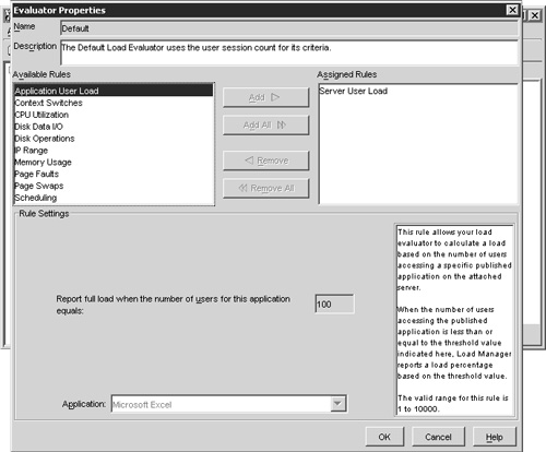
Figure 22.13. The Default load evaluator calculates user load based solely on the number of concurrent users.
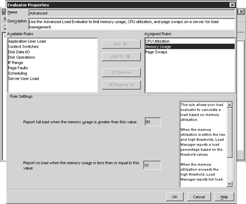
Opening the properties for the Advanced evaluator you will see that it does not determine server load based on the number of concurrent users, but instead on real-time performance statistics from the server. Specifically it looks at CPU utilization, memory usage, and the number of page swaps. Click an individual rule to see the specific settings, which will be displayed in the lower section of the dialog box. Figure 22.14 demonstrates this. It shows the settings for the Memory Usage rule. Just as with the Default evaluator, the Advanced evaluator is read-only, but it can be duplicated and edited if desired.
Before a server or application can be assigned a custom load evaluator it must be created within the Load Evaluators object. Once evaluators exist, they are easily assigned by right-clicking on an application or server and selecting the Load Manage Server or Load Manage Application menu option. A dialog box then opens allowing you to choose from either the built-in evaluators or any evaluators that you may have created on your own.
Figure 22.15 shows the Load Manage Application dialog box for Microsoft Excel, another application that I’m publishing in my farm. In this figure you can see that the MF01 server has an advanced evaluator assigned for MF01, but none assigned for MF02. This means that the Advanced evaluator will calculate the load for Excel on MF01. But on MF02, the load for Excel will be calculated using whatever evaluator is assigned to the server. This dialog box does not display the default evaluator for MF02.
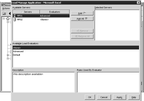
Figure 22.15. Load evaluators can be assigned to either the server or an individual application published on a server.
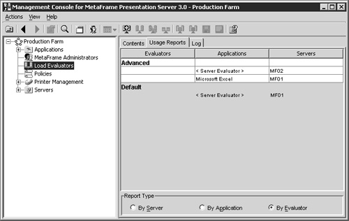
In order to see what the currently active evaluator is for a server or application, you need to return to the Load Evaluator component of the farm and select the Usage Reports tab from the right-hand pane. Figure 22.16 shows the By Evaluator report type, which lists all existing evaluators and what servers and/or applications they are assigned to. In this figure you will see that the Advanced evaluator is assigned to MF02, the Excel application runs on MF01, while MF01 is assigned the Default server evaluator.
Testing connectivity to a load-balanced application is a trivial exercise. Simply configure a couple of MetaFrame Presentation Server clients to access a published application that is being load-balanced between two or more servers. You will see the user sessions balanced among the available servers.
If launching multiple sessions from the same client, make certain that you are logging on using a different user ID. If multiple applications are published off the same MetaFrame server and multiple connection attempts are made to the farm using the same user ID, the user will have to continuously go to the same server. This is because once a user has an active session, the load manager will direct that user to the same MetaFrame server if another application that they are attempting to run is also published on that server.
In Chapter 7, “Server and Application Software Planning,” I talked about the advantages of using server cloning in a Terminal Server implementation to quickly build up an environment from a single base image. Using cloning you can ensure that all your Terminal Servers have an identical configuration. The advantages of cloning quickly become apparent in a large server deployment scenario, since a single server can be used during installation and testing of the operating system and software. Then when it comes time to test the configuration on multiple servers, you simple place the cloned server’s image onto the other hardware, and voilà, you have a multiserver environment. While alternatives such as scripted installations exist, I always select cloning if given the choice. Cloning can be ideal in a disaster recovery situation to get an environment back online as quickly as possible.
Figure 22.11 demonstrates how server imaging can be integrated into the build process for the Terminal Server environment. Of course, the environment could be created without the imaging step, but if a problem is encountered, it is highly likely that you would need to start all over again from the beginning to rebuild the server. If you have been maintaining server images, you can easily roll back to the point where you had a stable server configuration. For example, say that during the application installation phase you discovered a problem that left your Terminal Server unstable. You could quickly rebuild your server from the last image and re-evaluate the application installation process without having to completely rebuild the server from scratch. This process can be a valuable time-saver, even in a small Terminal Server implementation.
A key utility in the cloning process is the Microsoft SysPrep tool, the most recent version of which can be downloaded from the Microsoft Web site (http://www.microsoft.com). A version of SysPrep also can be found on the Windows installation CD, in the deploy.cab file. SysPrep is a tool specifically designed by Microsoft to prepare a server for cloning. Microsoft fully supports cloning of Windows Terminal Servers when this utility is used.
The first step in cloning a Terminal Server is to run SysPrep in order to prepare the server for cloning. SysPrep is run as follows:
First, create a directory called SysPrep off the root of %SystemDrive% and copy the files sysprep.exe and setupcl.exe into it. Both files are included with the SysPrep download file.
Next, remove the server from the domain and rename it if necessary. This way, when the cloned server is booted, it does not attempt to join the domain with a computer name already in use.
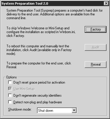
Now double-click on sysprep.exe to launch this tool. You will first see a warning message stating that the security configuration of the machine will be modified. After clicking OK to proceed you will be presented with the main System Preparation Tool setup dialog box (Figure 22.18).
In order to clone a Terminal Server, you will want to leave the default options as shown in Figure 22.18 and click the Reseal button, after which SysPrep prepares the system for cloning, and once completed, automatically shuts down the server. At this point you are ready to capture the actual clone image using either a cloning software package or rebooting the server into a second OS and performing a traditional backup.
After you capture the image, the next time you reboot the server from which you took the image, or boot any server you clone from the image, SysPrep automatically initiates a mini installation of Windows 2000 or 2003. This mini install prompts you for a subset of the information you would provide when installing a fresh copy of Windows.
Some of the information you are asked to provide includes such things as the desired regional settings, the product license key, the computer name, the administrative password, the date and time, the desired network components to install, and whether or not you want to join a domain. After all the required information is provided, the server automatically reboots and the cloned server’s setup is complete. The SysPrep directory of the %SystemDrive% is automatically deleted.
You can speed up configuration of a cloned server by using the Setupmgr.exe tool, which is included with the Windows deployment package for Sysprep. This tool can be used to create an answer file that is then used by SysPrep the first time a cloned server starts.
When you launch Setupmgr, it guides you through a wizard that generates an answer file called SysPrep.inf. Place this file into the %SystemDrive%SysPrep folder along with the other two executables. When the cloned server is booted for the first time, SysPrep runs and uses the answer file to configure the server. You can configure all the desired options within Setupmgr, including
The default server name to use.
The administrative password to use.
Unless you specify that you want this password to be encrypted, it will appear in plain text in the generated answer file. From a security perspective, I would recommend that you never store an administrative password in any form of answer file.
The default console display resolution and color depth.
Whether the server automatically joins a domain or workgroup.
If you will be completely automating creation of the cloned image, you should configure the answer file so that the server remains in a workgroup. This way, you have the opportunity to rename the server and add it to the domain immediately after the first boot.
The server’s time zone.
A sample answer file looks as follows:
;SetupMgrTag

[Unattended]
    InstallFilesPath=C:sysprepi386

[GuiUnattended]
    AdminPassword=*
    EncryptedAdminPassword=NO
    OEMSkipRegional=1

[UserData]
    FullName="Noisy River"
    OrgName="Noisy River"
    ComputerName=*

[LicenseFilePrintData]
    AutoMode=PerSeat

[SetupMgr]
    DistFolder=C:sysprepi386
    DistShare=windist

[Identification]
    JoinWorkgroup=WORKGROUP

[Networking]
    InstallDefaultComponents=Yes
When cloning a MetaFrame Presentation Server, there are some additional requirements that you will have to take into consideration. In particular, the type of data store that you have implemented will have an effect on exactly how you go about cloning the servers in your farm. The next two sections will discuss the basic imaging requirements depending on the type of data store that you have implemented.
When using the Access or Microsoft SQL Server 2000 Desktop Engine, the use of cloning is complicated slightly. Because the data store resides locally on the MetaFrame server, an image of the server hosting the data store cannot be used to build indirect servers for the farm. You will need to have an image of the first indirectly connected MetaFrame server in order to rapidly build additional servers for the farm.
Even though you cannot simply take an image of the data store server and use it to build indirectly connected servers, this doesn’t mean that you can’t leverage any application installation or configuration work that you may have already done on the existing data store server. In order to clone the existing data store server for use in building the base image for indirectly connected servers, you should do the following:
Make sure a local administrator has full administrative privileges in the MetaFrame data store.
Create an image of the existing data store but do not run SysPrep on the server first. Running SysPrep can cause issues with the server. You simply want to take a snapshot of the existing server as-is.
Now restore this image onto the new hardware. Make sure not to connect the server to the network. Because we have not run SysPrep, it still has the same PC name, so we want to keep it completely separate from the real MetaFrame server.
Log on locally to the server and uninstall MPS. This will completely remove all MetaFrame components from our cloned machine. After the uninstall has completed, reboot the server, continuing to keep the server off of the network.
Without removing the server from the domain, run SysPrep on the server and reboot. Do not clone the image yet. Once the server has restarted, proceed through the mini-setup wizard for SysPrep. Once that has completed you should have a new server with all of the same applications that are on the Citrix server that was cloned, except that this machine is running only Terminal Services. Log on and verify that the applications are still functioning properly.
Now reinstall MetaFrame on this server with an indirect connection to the original server that houses the data store. Once the installation has completed you will have a basic MetaFrame system with all of the same applications as the original server.
Once you have verified that you have a server in your farm that is not housing the data store, you can use this server to create an image that is then used to rapidly build new servers for the farm. The following steps apply to both indirectly connected (Access and MSDE) and directly connected servers ( SQL, Oracle, DB2).
This server image is built as follows:
Log on to the server to clone and delete the wfcname.ini file from the root of C:.
Stop the IMA Server and configure its startup state to manual.
If the server is running Enterprise Edition with Resource Manager then the local Resource Manager database needs to be deleted. It can be found in the %Program Files%CitrixCitrix Resource ManagerLocalDB and is called RMLocalDatabase.
Run Sysprep and save an image of the server when complete. The core image is now saved.
Deploy the image onto the new server and proceed through the mini-setup wizard. Once it has booted successfully restart the IMA server and set it to automatic. The service should successfully start and the server should be automatically added to the server farm.
You will need to verify that the zone information for the new server is correct. By default, a newly imaged server will add itself to the default zone, which matches the subnet of the MetaFrame server. Zone information is found within the Management Console, under the properties for the server farm.
At this point the server build is complete. Validate that the software on the server is functioning properly and add it into any desired application publishing setups. When first creating servers from cloned images it is always a good idea to test the server before putting it into production.