
CHAPTER 12
Conferencing
In this chapter, you will learn about
• Conducting a needs analysis for conferencing systems
• The technologies and protocols required to place a conferencing call
• How to include multiple participants in an online conference
• How to conduct online conferences that span multiple networks
With many other IP-based AV applications, your goal is to determine how to modify the content to fit the existing network. Streaming and digital signage fall into this category. Basically, if the network doesn’t have enough bandwidth to deliver high-quality video in real time, these applications can accept a degree of latency or compression.
Conferencing is different because it’s interactive. You can’t expect users to wait online while audio and video data buffers, or to communicate through a haze of dropped packets. In fact, when it comes to online conferencing, any delay is generally considered unacceptable. The goal of conferencing is to create the effect of remote meeting participants sitting in the same room.
Customers expect AV professionals to perform this magic trick without requiring much effort on their part. For users, starting a conference should be no harder than dialing a phone. When it comes to networked AV systems, however, it’s not that simple. In this chapter, we will explore how to achieve a real-time connection between two networked communication devices.
Conferencing Needs Analysis
As with any AV system, you need to perform a needs analysis before designing a conferencing system. Refer to Chapter 11 to understand the many whys and wherefores of a needs analysis, then prepare to ask questions specific to conferencing systems.
Use the list of questions in this section to gather information from customers about their online conferencing requirements so you can match them with the right application. Don’t worry if you don’t understand some of the concepts; we will cover them throughout this chapter. As always, consider how the users’ answers to these questions might impact the network, the system’s design, and the cost.
Audience
1. Who is the intended audience?
2. Where is the intended audience (onsite, within the LAN; offsite, within the company WAN; offsite, outside the company WAN; etc.)?
3. If conferencing will take place over a WAN, how many different sites/zones are there?
4. What are the audience access control requirements?
Endpoints
1. How many different endpoints will participate in each conference?
2. What kind of endpoints will participate in conferences (desktops, mobile devices, large displays, etc.)?
3. How many users will be at each endpoint?
Content
1. What kind of media do users need to share during the conference (audio, video computer screen, etc.)?
2. What level of image quality is expected by users and/or required to support the conferencing tasks?
3. What are the accessibility requirements, if any?
Related Applications
1. Will the conferencing system be a source for streaming or video on demand?
2. Will the conferencing system be part of a unified communications (UC) solution?
Bandwidth Availability
1. What is the network’s total available bandwidth?
2. Has QoS been implemented? If so, what queue level will AV traffic occupy?
3. Does the network support MPLS (Multiprotocol Label Switching)?
4. Where might bottlenecks occur?
Latency
1. How much latency is inherent to the network?
2. Will there be any Transport Layer security requirements (e.g., encryption)?
Network Policies
1. Is an IP conferencing protocol (SIP or H.323) already in use by other systems? If so, which?
2. Will those systems be integrated with the conferencing system?
3. What types of conferencing programs have already been approved?
4. What types of conferencing programs have already been forbidden?
5. What is the organization’s UC strategy?
6. What conferencing manufacturers have already been approved?
Placing the Call
An IP network-based conference (featuring audio, video, or both) begins in much the same way as any information transaction between two networked devices: with session negotiation. This is the step at which both ends of a data link reveal their capabilities and agree on how they’re going to communicate. Protocols, endpoints, and media may vary, but the general steps are the same (see Figure 12-1):
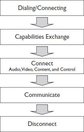
Figure 12-1 The steps of a conferencing session negotiation.
1. The first conferencing device dials the second, using an IP or DNS address.
2. The second device answers and sends a reply.
3. The two devices conduct a capabilities exchange, or “caps exchange,” asking each other what type of media they can send and receive and how quickly.
4. The capabilities themselves—audio, video, control, and connection speed—are then selected. The devices agree on a codec and detect the highest bit-rate streams that each is capable of receiving.
5. The audio, video, and control streams then attempt to connect through their individual ports.
How devices in an online conference handle session negotiation varies. The protocols required to establish communication form the basis of successful online conferencing.
Conferencing Session Protocols
In networked-based conferencing, a session protocol handles the capabilities exchange, access management, and the process of gracefully starting and stopping a conferencing session. Historically, IP-based videoconferencing has used the H.323 session protocol. Increasingly, however, efforts to adopt what the industry calls “unified communications and collaboration” (UCC) is driving a transition to Session Initiation Protocol (SIP)–based conferencing. AV professionals need to be aware of the differences between these protocols, why they might choose one over the other, and how to navigate the transition between them.
 NOTE Unified communications and collaboration is an AV/IT industry phrase used to describe the integration of all networked-based communication methods, from conferencing to email and online chat to IP telephony. Often referred to simply as unified communications (UC), UCC is not a single system but usually several services accessed through one interface.
H.323
H.323 was created by ITU Telecommunication Standardization Sector (ITU-T) specifically for multimedia communications. It is an umbrella protocol, encompassing several other communication protocols used to describe standard methods of encoding and decoding conferencing streams, message formats, control services, and more (see Figure 12-2). Taken as a whole, H.323 protocols ensure a conferencing system’s ability to
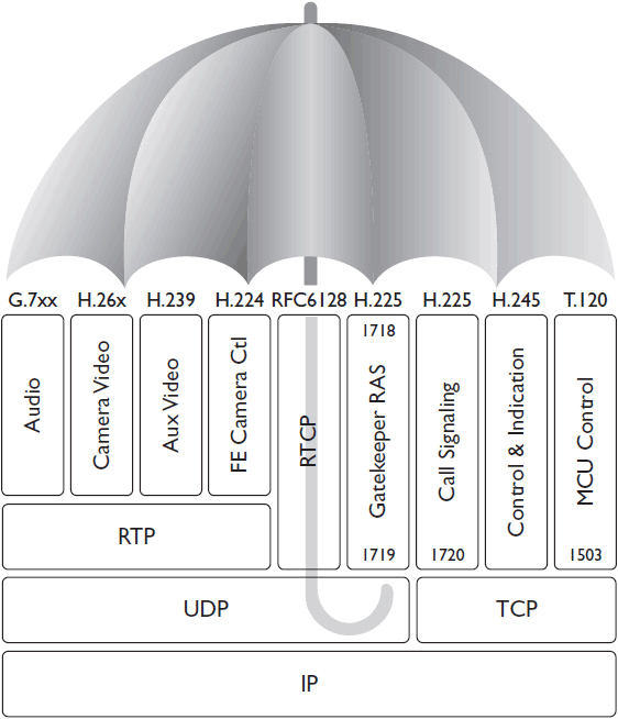
Figure 12-2 H.323 is an umbrella protocol covering many capabilities.
• Set up audio and video calls
• Exchange endpoint capabilities and choose the highest-quality codec and bit rate for all endpoints
• Register terminals to a gatekeeper, providing admission control and call routing
• Hold multipoint conferences
• Share presentation content alongside a live AV stream
• Enable far-end camera control (FECC), which allows conference participants to pan, tilt, and zoom a camera at the other end of a conference
• Encrypt calls using the Advanced Encryption Standard (AES)
Call setup and control of an online conference session are accomplished using TCP, but the audio and video of the session itself are delivered via UDP/RTP.
H.323 enjoys widespread adoption among videoconferencing manufacturers because it’s feature rich and tailor made for multimedia collaboration, and offers interoperability among devices from different providers. Today H.323 is the more established IP video protocol.
For networked AV applications that include only traditional videoconferencing endpoints—immersive, room-based, or desktop systems—H.323 is usually the best choice for session protocol. But H.323 is also very specialized. The more a customer wants to adopt UCC—in other words, integrate VoIP, instant messaging, or other communication systems not originally envisioned by H.323—the more they may need to consider an alternate protocol, such as SIP, or to run both protocols in what’s known as a dual-stack system.
Keep in mind, because modern firewalls don’t allow unrestricted open ports for networked communications or other AV sessions, firewall traversal for H.323-based conferencing can be a challenge. When designing a conferencing system, it’s important to communicate to IT the network ports that the system will use.
H.323 uses these IP ports:
• Statically assigned TCP ports 1718 to 1720 and 1731 for call setup and control
• Dynamically assigned UDP ports in the range of 1024 to 65535 for video and audio data streams
Session Initiation Protocol
The Session Initiation Protocol (SIP) is an IETF standard designed to control communication sessions over IP. Unlike H.323, SIP was not designed specifically for multimedia communications; it was designed for many types of communication sessions, including videoconferencing, VoIP, instant messaging, presence applications, and more.
NOTE In IP networking and unified communications, presence applications indicate whether a user is online and available to communicate. If you’ve ever used Skype for online calling, you know a small green icon means a person is online (a red icon means “do not disturb.”)
SIP employs DNS addressing so that users can call other users instead of rooms or devices. A user has a domain name, such as [email protected], that identifies them in a SIP application.
Instead of requiring fixed H.323 terminals, SIP allows users to log in to any SIP-enabled device (a “user agent”), allowing greater mobility. User A can log on to her laptop, cell phone, or immersive telepresence room and make it her user agent. Anyone calling her using her domain name will be able to reach her wherever she is located.
Like H.323, SIP uses UDP/RTP transport to share audio and video streams. It can encrypt streams using AES and send dual video streams (live video plus computer-generated content). There’s even a way to create a tunnel through a SIP session to support far-end camera control.
SIP was originally designed to be a more scalable protocol than H.323, with only a handful of specifications. However, since SIP’s inception, the IETF has produced more than 140 RFCs, adding to the functionality and capabilities of SIP implementations. As a result, no two manufacturers implement SIP in precisely the same way because each uses a different set of RFCs.
When it comes time to communicate port requirements to IT, SIP uses TCP or UDP port 5060 to connect to SIP servers and endpoints for nonencrypted signaling. It uses TCP or UDP port 5061 for encrypted SIP traffic. Ports for the AV streams themselves are negotiated by the Session Description Protocol (SDP) during the session initiation.
Gatekeepers and Servers
In networked conferencing, one device can call another using the latter’s IP address as a kind of phone number. However, most people these days don’t memorize all the phone numbers they frequently dial—let alone cryptic IP addresses. They use contact lists or personal phone books and simply select the person they want to call. Conferencing session protocols support specialized systems that, among other things, can act as a contact list for approved conference participants.
H.323 Gatekeepers
An H.323 gatekeeper is a piece of software that runs on a network administration computer. In H.323-based conferencing, the gatekeeper defines and controls how voice and video communications are managed over the IP network.
All conferencing endpoints register with the gatekeeper. The network administrator can then configure, monitor, and manage the activities of registered conferencing endpoints, set policies, and control network resources, such as bandwidth usage, within the H.323 zone.
The H.323 gatekeeper is responsible for
• Providing address translation between LAN aliases (e.g., “Conference Room 1”) and IP addresses
• Call control
• Routing services to the H.323 endpoints
• Conferencing security policies
• Overall conferencing system management
In H.323 conferencing, the gatekeeper provides all the registration, admission, and status (RAS) communication services between conferencing endpoints. Only endpoints registered to the gatekeeper can use the ports set aside for conferencing. Gatekeepers allow users to either place calls directly between endpoints or route the call through the gatekeeper.
SIP Servers
SIP-based conferencing systems handle RAS functions differently than H.323 systems. SIP separates many of the features of an H.323 gatekeeper into individual servers. SIP servers enable SIP endpoints to register user location, exchange messages, and send data across networks. Network administrators can manage routing, security policies, user location, and more using the SIP servers.
SIP server functionality is divided into three main categories, which may or may not run on separate physical devices:
• A SIP registrar server handles location registration messages, effectively managing who is and is not allowed to make calls. It uses a location database to store and retrieve user registration information. The location service and the SIP registrar may or may not reside on the same machine.
• A SIP redirect server returns “contact this address” responses. In short, the redirect server receives a SIP request, but if the user that the caller is trying to contact is not currently at the specified address, the SIP redirect server responds with a different address at which the caller can reach the intended user. Possible SIP redirect server responses include the following (the numbers correspond to standard HTTP status codes):
• “300 Multiple Choices.” A SIP redirect server returns this response when the requested address corresponds to several different locations or user agents. The caller can then choose which specific endpoint to contact.
• “301 Moved Permanently.” A SIP redirect server returns this response when the user can no longer be found at the requested address. The new address is included in the contact field.
• “302 Moved Temporarily.” A SIP redirect server returns this response when the user is temporarily located at a new address. The contact field may also include how long the new address will be valid.
• “305 Use Proxy.” A SIP redirect server returns this response when the user can only be contacted via a proxy—some interim address—which is specified in the contact field.
• A SIP proxy server forwards SIP requests and responses, including call and session information. SIP proxies may be stateful or stateless, as described here:
• A stateful proxy monitors data transmission and message history, allowing it to resend lost packages. Stateful proxies require more memory and processing power than stateless proxies.
• A stateless proxy does not monitor data after it has been forwarded. In fact, it “forgets” it ever handled the data at all. It cannot retransmit lost packages or monitor transmission success.
Routing Modes
Gatekeepers and SIP servers can monitor and control a lot of call data and parameters or very little. The amount of data that gatekeepers or SIP servers manage—and therefore, the amount of work it takes to configure them—depends on the system’s dial plan, namely, the way the system is set up to route calls. The simplest dial plan is direct mode.
Direct-Endpoint Calling Mode
In direct mode, the gatekeeper or SIP server basically acts as a phone book. The initiating endpoint requests permission from the gatekeeper to make a call. If permission is granted, the gatekeeper returns an E.164 address translation and then drops off the call. (You will learn about E.164 addressing later in this chapter.) More specifically, in tech jargon:
1. Endpoint A sends an ARQ (admission request) to the gatekeeper.
2. The gatekeeper returns an ACF (admission confirmation) with the IP address of the endpoint.
The endpoints are now in direct communication; no further data is routed through the gatekeepers. Direct mode is the simplest to configure and requires the least processing. Nearly all gatekeepers support this mode—and many support only this mode.
Gatekeeper-Routed Calling Mode
If you want to use the gatekeeper to exercise more control over conferences, choose routed mode. Routed mode falls into two categories:
• H.225 routed mode performs all direct-mode functions and handles all H.225 call setup messages. This means the gatekeeper can control the overall bandwidth of the conference call.
• H.245 routed mode routes all data except the media packets themselves through the gatekeepers. This allows the gatekeeper to control the AV codec, individual conference flows, and overall bandwidth.
Routed mode requires more processing than direct mode, but offers more capabilities. Most modern gatekeepers support one or both routed modes.
Full-Proxy Calling Mode
It’s also possible to route all call data, including the AV streams, through a gatekeeper. This is known as full-proxy mode. The gatekeepers act as proxies for the endpoints involved in a call.
Full-proxy mode requires a great deal of processing power and is therefore not available on many gatekeepers. However, it offers several advantages, including
• Added security. The endpoints cannot see each other’s real identity or IP address; they only see the gatekeeper.
• Firewall traversal.
• H.323-SIP internetworking. Conferencing applications using a multiprotocol conference server to connect H.323 and SIP endpoints must use full-proxy mode.
• Back-to-back user agents.
• IP version traversal on some gatekeepers in full-proxy mode.
Where to Install a Gatekeeper or SIP Server
You should locate a gatekeeper or SIP server at each physical site on the LAN (see Figure 12-3). Depending on your call-routing technique and redundancy requirements, you may require several gatekeepers at each location.
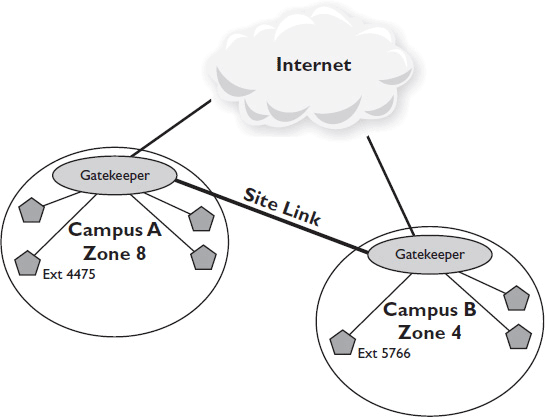
Figure 12-3 Positioning gatekeepers.
Full-proxy mode conferencing may require several gatekeepers to handle the processing of simultaneous calls. Manufacturer specifications should indicate how many simultaneous direct, routed, or full-proxy calls a gatekeeper can handle. You may also need multiple gatekeepers to handle multiple sets of dial rules.
Finally, if gatekeepers are responsible for call routing and admission control, you should also include backup gatekeepers in case one fails.
Calling Multiple Endpoints
Conferencing applications come with measurable minimum requirements, particularly when it comes to acceptable latency. If the requirements aren’t met, the application fails.
For real-time, interactive communications, any technical measures aimed at improving quality and intelligibility that also introduce latency should be considered off the table. When you’re analyzing a network environment for its suitability to conferencing, you’re not merely asking, “How much content can the network handle?” You’re trying to determine whether the network is capable of meeting the client’s needs at all.
As online conferencing includes more participants, meeting bandwidth and latency requirements becomes a greater challenge. Furthermore, as you add different types of endpoints to the mix, interoperability becomes more difficult to achieve. Calling among multiple endpoints is where the challenge of IP-based conferencing truly begins.
Multipoint Control Units
A multipoint control unit (MCU) is a device that facilitates conferences among three or more endpoints. All the individual conference streams are sent to the MCU, which returns a combined stream to participants. Many MCUs also include gateway functions, as well as translation among POTS (plain-old telephone service), ISDN, IP, H.323, SIP, and so on.
An MCU allows users to configure the way that multiple participants appear in an online conference. It may show
• only the people who are talking
• everyone, with the screen broken up into quadrants
• everyone, as if they were sitting together around a table (in the case of immersive videoconferences, sometimes known as telepresence).
Most MCUs operate in three modes:
• Switched mode, where only one AV stream at a time is transmitted to all participants. As different participants speak, the MCU switches among streams.
• Continuous presence, where all participants receive the data stream continuously from all other participants.
• Hybrid mode, where the participant speaking is allotted a higher-quality data stream than other participants.
An MCU may be a hardware- or software-based device. Hardware and software conference devices differ in the number of streams and types of codec they support. For software-based conference devices, you can adjust the number of streams. Hardware-based conference devices, however, support a fixed number of streams.
MCUs are typically sized according to peak usage, but every MCU manufacturer defines “peak” differently. They may measure in terms of the peak number of open ports or connections, peak bandwidth throughput, or peak CPU resource usage.
Because an MCU receives every stream participating in a conference, it needs to be located centrally on the network. It also needs a lot of bandwidth—enough to accommodate the peak bandwidth of the entire system, plus overhead. As a result, MCUs, like video-on-demand content servers or streaming servers, are usually located as close to the network backbone as possible. In fact, they’re often leased as a service from an ISP or cloud provider.
Depending on your customer and the scope of the conferencing system, you may also need to locate MCUs regionally. For example, if an enterprise has offices in the United States and China, it locates one MCU in China that can accept six calls in that region and one MCU in the United States that can accept six calls in that region. However, only one call can be placed between the two locations.
Conferencing Endpoints
In conducting a needs analysis for a conferencing application, pay special attention to the system’s endpoints. In general, you can think of conferencing endpoints in four categories (see Figure 12-4):
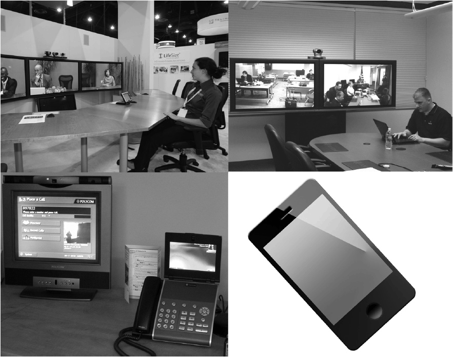
Figure 12-4 Categories of conferencing endpoints.
• Immersive systems, often referred to as telepresence systems, use several simultaneous video feeds per room, along with a carefully replicated room setup and precise environmental specifications, to create the illusion that conference participants are seated across the table from one another. Immersive systems place a premium on image quality and typically require 4 to 6 Mbps of bandwidth per stream.
• Room-based systems are rooms equipped with permanent videoconferencing equipment, such as boardrooms or classrooms. Depending on the image size and frame rate, a room-based endpoint may require 512 kbps to 1.2 Mbps per stream.
• Desktop systems are all-in-one units that combine a camera, microphone, screen, dialing mechanism, and codec in a single device. Like room-based systems, desktop systems typically require between 512 kbps and 1.2 Mbps per stream.
• Mobile and/or software-based endpoints may be optimized for delivering conferencing streams over Wi-Fi or other wireless networks. They typically require 512 kbps or less of bandwidth per stream, with the associated drop in expected quality. Skype (now run by Microsoft) and Apple have led the adoption of proprietary mobile and software-based conferencing for consumers. People who’ve learned how convenient it is to connect with family via Apple FaceTime want to be able to achieve the same sort of accessible communication with work colleagues. However, if they need to communicate with any of the endpoint types listed here, customers should be advised to steer clear of proprietary consumer brand names and adopt standards-based conferencing—at least until companies figure out how to better patch a Skype video call into a telepresence session, for example.
In fact, conferencing interoperability is hard to achieve in a system with many different types of endpoints. Given this challenge, try to live by this advice: “The more types of endpoints a conferencing system includes, the fewer device manufacturers should be involved.”
From a purely practical standpoint, if a system will include immersive, room-based, desktop, and software-based conferencing, you may want to consider a single manufacturer solution. Emerging cloud-based bridge and gateway services can also provide interoperability among disparate platforms.
How do you determine which types of endpoints to include in your videoconferencing system? This is a matter of balancing your customer’s needs with network reality. You must examine the tasks that users are trying to accomplish, the media they’re using to do so, and the audience at each endpoint.
Although it’s tempting to set room factors aside entirely during the design of network systems, in the case of conferencing, room characteristics can impact required network resources. Take, for instance, the number of participants per endpoint. If many users will be participating in a conference using a single room-based system, you’re going to need a big display so everyone in the room can see. A big display usually means that higher resolution is required for optimal image quality; highly compressed images look a lot worse when the artifacts are three inches tall. Higher resolution requires more bandwidth.
Like all AV design, the process of selecting endpoints is iterative. Your customer may want the quality and experience of an immersive telepresence system, but is the customer ready to commit to running one conferencing codec per person? Does the network have the bandwidth to support that? Does the facility have the spatial resources for a single-purpose room? What your customer wants, needs, and can actually use may be three very different things.
As you select conferencing endpoints, pay attention to how the videoconferencing codecs are licensed. This can be a big “gotcha” for the overall cost of the system. Will you pay based on the number of registered users? The number of registered endpoint devices? If you’re using SIP conferencing, those could be quite different. You will need to conduct a cost comparison of licensing types to determine which works best for your customer’s number of users, endpoints, and call volume.
Directory Integration
One of the principal benefits of networked AV systems, especially as they relate to conferencing systems, is the ability to integrate existing network directories. Directories can contain user contact information, calendar and scheduling data, device configuration data, and more. Tapping into these systems can increase the functionality and ease of use of a conferencing system because it can make it easier to locate and connect with room-based or desktop-based conferencing endpoints.
Directory servers are typically accessed and queried using Lightweight Directory Access Protocol (LDAP) over port 389. Using LDAP, you can search for and retrieve directory entries; add, delete, or modify entries; and more. In the context of networked AV systems, this allows you to
• Integrate the enterprise’s directory of contact information into a conferencing system
• Automatically generate schedule information on digital signage outside a conference room
• Remotely view and maintain device profiles
Microsoft’s Active Directory and IBM’s Lotus platform are probably the most common LDAP integrations for AV applications. For example, a videoconferencing codec may use Active Directory as a user directory, automatically pulling in contact information for scheduling and initiating video calls. When installing a conferencing system, AV professionals must work with their IT counterparts to integrate directory services.
E.164 Addressing
Computers naturally identify each other by IP address. As conferencing systems include more heterogeneous endpoints, however, the endpoints need a more universal means of contacting one another. Specifically, what if a participant wants to join your videoconference via phone? How will the phone contact your computer? Your gatekeeper or SIP server should allow you to map by means other than the IP address to each resource in the system.
E.164 is the ITU-recommended scheme for numbering public telecommunication systems. It provides a universal dialing scheme. This is the numbering scheme that defines the format for telephone numbers.
E.164 numbers have a maximum of 15 digits. In the case of network devices, a network identification code also falls between the country code and the subscriber number. They are usually written with a + prefix, followed by a country code and subscriber number. They are ordered in the opposite manner from a domain name. (See Figure 12-5.)
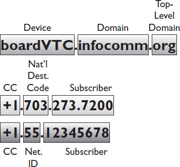
Figure 12-5 IP versus E.164 addressing.
Domain names have the most specific information to the right and the least specific to the left. E.164 addresses begin with the most general information (the country) and drill down to the individual client. An E.164 alias can be assigned to an H.323 endpoint or SIP user, allowing that device or person to be called from a traditional telephone. Like IP addressing, this mapping may be static or dynamic.
In static E.164 numbering, the gatekeeper that translates telephone calls to IP calls is loaded with a configured list of E.164 phone numbers and IP addresses. Whenever a particular E.164 address is dialed, the gatekeeper translates the number into the same IP address. This is the simplest numbering system to configure, but there’s an obvious catch: in order for the E.164 address translation to remain static, the IP addresses of the endpoint devices must also remain static. Though this can be accomplished through reserve DHCP addressing, it does have several drawbacks:
• It excludes mobile endpoints. As a mobile device changes IP networks, its IP address must change as well. Therefore, it cannot have a statically configured IP address.
• If the network has to be renumbered as a result of switching ISPs, for instance, the entire list must be reconfigured by hand.
• If the primary gatekeeper fails, there is no way to locate a secondary device.
• It limits registered SIP users to a single endpoint.
E.164 addressing can be mapped to dynamic addresses. Instead of mapping to an IP address, the E.164 address is mapped to a uniform resource indicator (URI), which is essentially a domain name. When a user dials the E.164 address, the gateway sends a request to the DNS server to retrieve the device’s IP address. In the case of SIP conferencing, the gateway will first query the SIP server to discover the user’s current user agent and then request that device’s dial plan.
Dynamic E.164 address translation is more flexible than mapping to an IP address. It accounts for mobile endpoints, network renumbering, and gateway failure, and leverages the full potential of SIP conferencing. However, it does require that all endpoints in the conferencing system be registered to the DNS server with a URI. As a result, dynamic E.164 requires far more configuration during the system launch. For conferencing systems requiring flexibility, however, it may still save you considerable pain in the long run.
Conferencing as a Stream
One of your conferencing endpoints may in fact be a streaming server or video-on-demand content server. If you’re using a standards-based conferencing device, the conference is already being treated as a stream.
Major manufacturer videoconferencing codecs may have streaming built in; if so, it just needs to be enabled. Once you’ve configured your conference as a stream, you can store, record, and retrieve it like a stream. In that case, though, the bandwidth requirements for the application will double, as each stream is sent to the streaming server as well as the conference participants.
SIP and Unified Communications
SIP has some clear benefits—DNS dialing, in particular—but it also has some drawbacks. H.323 interoperability is more reliable, for instance.
What, then, is driving the push toward SIP adoption? Unified communications. As we touched on earlier, unified communications (UC) describes the process of combining voice, video, and data on a single enterprise IP network with the ability to seamlessly move from one form of communication to another (e.g., from an instant messaging session to a phone call to a videoconference session). To make it possible, VoIP, presence, instant messaging, and videoconference systems must be aware of each other and be able to communicate.
UC ranges from the very simple, such as the unified contacts in an iPhone, to the very complex. For instance, a UC system may include rich presence capabilities that allow a call to be directed to anyone with a preferred skill set (such as anyone who can help you fix your PC when it’s not working) rather than a particular person. Such a system might allow you to locate and route a call from a Spanish-speaking customer to the nearest Spanish-speaking sales representative. A smart building with RFID tags might know where a person is located and ring whatever phone is nearest, automatically turning it into a user agent. The UC system may also know through the presence engine that a person is in a meeting and direct the call to voicemail, which the user then receives via email.
For the end user, UC strategies are intended to let the technology fade into the background, making technology-enabled communications easier, more natural, and more efficient. Some users appreciate this more than others: make sure you discuss whether and how people can be allowed to go “off the grid.”
Implementing a UC solution requires you to be very aware of the secret eighth layer of the OSI model: people and politics. No one service provider will ever own all the systems that make up a UC solution. Successful UC implementation requires patient coordination among IT, VoIP, AV, and other service providers. Be prepared for UC design to be a very IT-driven process, however. In a UC environment, you will likely be limited to the manufacturers that the enterprise is already using for their VoIP products or presence engine. The UC solution will ultimately be driven by a centralized phone book or presence engine from which all the other systems derive contact and availability information. If the videoconferencing system isn’t compatible with that central directory, it cannot be a part of the UC environment.
Enterprise video is a late arrival on converged networks. VoIP, central directory, presence, and instant messaging have all existed on the same data networks for years, and they all use SIP to initiate calls. Videoconferencing systems that will be part of a UC solution—now or in the future—must be able to hold SIP sessions.
Types of Conferencing Media
Today’s end users are conditioned to expect high-definition video for all applications, and many customers will say they want “HD conferencing.” Not all high-definition conferencing is created equally, however. SD, HD, CIF, and SIF all refer to the image’s resolution. They don’t define a stream’s frame or bit rate.
For your reference, Tables 12-1, 12-2, and 12-3 list common videoconferencing formats and resolutions.
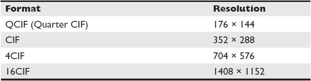
Table 12-1 Common Intermediate Format (PAL)
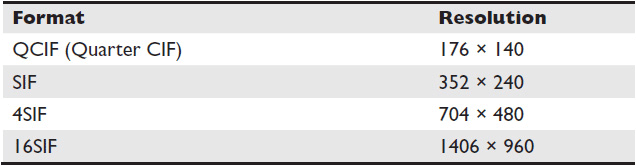
Table 12-2 Standard Intermediate Format (NTSC)
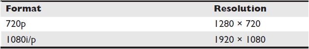
Table 12-3 High-Definition Formats
Technically, it’s possible to stream an HD video feed at 512 kbps—the stream just has to be thoroughly compressed during the encoding process. This heavily taxes the processors at the encoding and decoding ends of a call and introduces latency as the stream is packed and unpacked. Depending on the level of detail and motion in the captured image and the type of compression used, this can introduce so many artifacts and drop so many packets that the resulting conferencing stream is unwatchable.
Just as you would for a streaming application, try to lead the customer past the quality they think they want to the quality they actually need in order to accomplish their tasks. Depending on network availability, the customer may experience much higher call quality with standard definition than with HD. Don’t let the customer bite off more image resolution than the network can chew. It may be very gratifying to sell an expensive, high-definition telepresence system, but if the resulting call quality is terrible, you will lose the potential of any future business with that customer.
Digital Audio Standards: ITU
We don’t think about it much, but a videoconferencing system needs a soundtrack—basically, the audio stream of people’s conversations. The ITU defines the audio encoding standards used primarily for VoIP and videoconferencing. (See Table 12-4; the most common standards appear in bold type.)
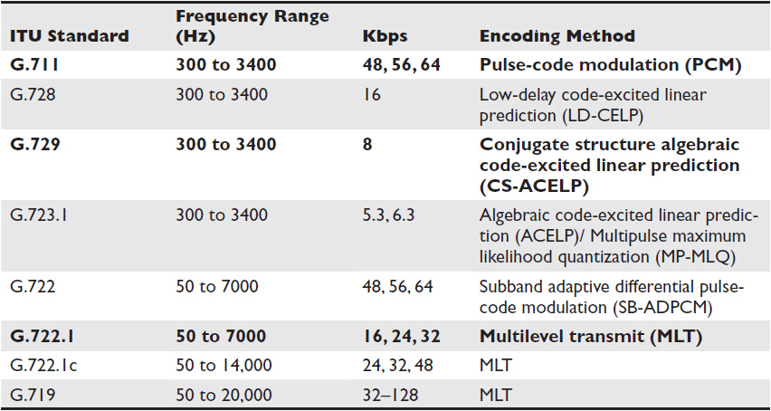
Table 12-4 ITU Audio Standards
Conferencing and Bandwidth
The rules for bandwidth usage are the same for IP-based conferencing as they are for streaming. Differentiated quality-of-service mechanisms are an absolute necessity for converged networks. In general, videoconferencing should be assigned its own class of service, and that class should be higher than anything else on the network (save, perhaps, VoIP).
Bandwidth is only relevant in terms of a particular network segment. Its usage isn’t cumulative; if you’re using 4 Mbps on one network segment and 4 Mbps on another network segment, you’re still only using 4 Mbps, not 8 Mbps. When you calculate bandwidth required for a conferencing application, your goal is to determine the peak usage per segment.
The formula for determining the bandwidth required per segment for a multipoint videoconferencing call using an MCU is
(Bit Rate + 20% Overhead) × Number of Simultaneous Calls = Bandwidth Required
Each endpoint participating in the call counts as a simultaneous call.
NOTE If a conferencing system traverses an IPsec-based VPN for securely patching in remote participants, the VPN wrapper may add an additional 5 percent to the required bandwidth to account for overhead.
As an example, a multipoint conference call has six endpoints, as shown in Figure 12-6. Two desktop units, located at the same site, have negotiated a 768 kbps stream. The remaining four endpoints, each located at a different site, have negotiated a 1.9 Mbps stream. The network has a hub-and-spoke topology, with the MCU and one of the endpoints located at the hub. How much bandwidth is required for the call?
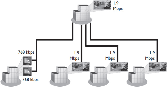
Figure 12-6 A multipoint conference call with six endpoints.
One of the sites, the hub, will have all the calls traveling on its network segment, so it will experience peak bandwidth usage. Here’s the math:
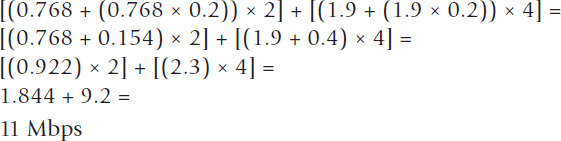
Assuming 30 percent of the network is available for conferencing, how much total available bandwidth should the network have?
11 / 0.3 =
37 Mbps
The other sites that negotiated 1.9 Mbps streams will each use 2.3 Mbps of their local segments. The site running two 768 kbps streams will consume 1.844 Mbps of its segment.
Dedicated Network Links for Videoconferencing
Because of high bandwidth requirements, heavy users of high-definition videoconferencing may have to provide a dedicated network link for the system, either physically separate or on a VLAN. If you, as the system designer, can get access to a dedicated link, it gives you a lot more room to maneuver in terms of bandwidth. Because you no longer have to worry about any bursty data traffic, you can use up to 70 percent of the network’s available capacity for video. Because audio is less bursty than video, audio-only applications can use even more of the network’s capacity.
There is an important exception to this rule: If a network uses Multiprotocol Label Switching (MPLS) to route data, you may still be limited to 30 percent or less even for dedicated links. This is because the video traffic may be using the same access link as the data traffic to access the MPLS provider. This creates a bottleneck that puts video traffic in competition with other data, as if it were on the same network. If your customer uses MPLS to route data, ask if they can provide a separate access link for any dedicated video links.
You Try It: Videoconferencing Bandwidth
Four sites in a fully meshed, wide area network will participate in a multipoint conference call. Each site has negotiated a 1.5 Mbps stream. The MCU is centrally located between sites on the network backbone. How much bandwidth is required for the call?
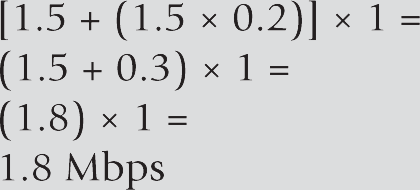
In this case, there is only one caller per network segment. Each caller sends a stream from a different site to a centrally located MCU. Because the WAN is fully meshed, each site has its own pipe to the MCU. The call will consume 1.8 Mbps of bandwidth on each segment.
Videoconferencing Latency
Streaming applications can tolerate a wide range of latencies. Videoconferencing cannot. Your videoconferencing manufacturer should indicate the latency requirement for the system. Many manufacturers claim to be able to tolerate latencies of up to 200 ms. Such specifications should be treated as an absolute maximum. Latency can begin to create noticeable lag long before that point. As a result, IEEE 401 recommends an end-to-end latency delay of no more than 100 ms.
Verify the latency inherent on a WAN using a speed test tool. If the inherent latency exceeds 100 ms, you may have to specify dedicated videoconferencing links between locations, or an entirely separate videoconferencing network.
If the videoconference has any security or encryption requirements, these will introduce latency into the system as encrypted content is processed. There’s no way around this. Make sure your customer acknowledges in the SLA the extra latency that security requirements introduce.
Mitigating Videoconferencing Bandwidth Requirements
If your conferencing network cannot meet bandwidth requirements, you have a few options for reducing network usage:
• Buy more bandwidth If high-quality conferencing is extremely important to the customer, throwing money at the problem by purchasing separate links or increasing the capacity of its existing network is an option.
• Limit the allowable bit rate for videoconferencing You can establish rules on your H.323 gatekeeper or SIP server that will prevent endpoints from being able to negotiate conferencing streams above a preset threshold.
• Limit the number of simultaneous calls In the SLA, specify the number of simultaneous calls for which you’re willing to guarantee system performance. You should do this regardless, but it’s especially important in cases where the existing network cannot meet the client’s original need.
• Establish rules on the H.323 gatekeeper or SIP server to manage bandwidth The gatekeeper can be configured to deliver the best available streams dynamically to all conference participants based on preset thresholds.
Gatekeeper/SIP Server Business Rules
On your gatekeeper or SIP registrar and proxy servers, you will have the opportunity to define business rules. The rules can improve conference security and help you manage bandwidth. Consider defining rules for the following:
• Authentication Will you allow only certain endpoints to register, or are you allowing everyone? If the former, do you want to block rogue access so only people registered to the gatekeeper can access VTC resources?
• Dial rules Who can call whom? Setting these rules helps control bandwidth usage as well as access to personnel. For instance, you may want to establish a rule that only allows executives to call other executives.
• Call routing technique Will calls be direct, routed, or full proxy?
• Bandwidth allocation How much bandwidth will you make available? You can implement rules limiting the size of all calls within the enterprise, setting specific bandwidth thresholds for particular endpoints, or limiting the size of calls to certain locations (e.g., all calls on the enterprise can be no more than 768 kbps, the immersion facility can go up to 4 MB, limit the size of calls to Africa, etc.). “Size” limitations could be different depending on your needs and licensing structure. You may need to limit the total number of simultaneous calls, bandwidth allocated to each participant, or bandwidth allowed per network segment.
Calling Across Networks
Up to this point, we’ve discussed elements of networked systems you can control: the devices you employ, how users within an organization use them, how a network will be set up to handle the traffic, and so forth. Conferencing applications mean giving up a lot of that control, because they typically involve inviting outsiders into the enterprise network. This is a prospect that puts many network managers on high alert and motivates many organizations to quarantine their conferencing equipment as if it were a conduit for plague rats rather than data packets.
This is not irrational. When a customer wants to patch in participants from outside the enterprise network, there are no security guarantees. The organization has no control over what kind of endpoints external participants use, which session protocols they employ, or how much bandwidth they have available. Moreover, it can’t trust outsiders to keep the organization’s network secure. Would you count on external conference participants to keep your internal IP addresses private? Would you trust them to ensure that only approved traffic comes through your conferencing ports? No, and neither should your customer.
In this section we explore how to navigate the issues involved in conferencing across networks. When you have no control, how do you protect a network while ensuring the system still works?
H.323-SIP Internetworking
When designing a customer’s conferencing system, you may come across a situation where the organization runs different types of conferencing networks within its own WAN. On one hand, the customer may need a SIP-based conferencing system to communicate with other systems in a UC environment. On the other hand, most IP-based videoconferencing systems are H.323 based, and chances are the customer may need to communicate with external systems. The good news is it’s possible to include both H.323 and SIP endpoints in the same conference.
There are three approaches to holding conferences among H.323 and SIP endpoints:
• Using an H.323-SIP signaling gateway, the signaling data can be transcoded while the RTP media stream is left intact. This preserves video quality while translating the call setup information. Keep in mind, some information will be lost in the process. The gateway interrupts the encryption key exchange process, resulting in unencrypted conferences. Video channel control information may also be lost.
• The signaling and media information may be sent to a multiprotocol conference server, which transcodes the entire data stream to the appropriate session protocol before forwarding it to its endpoint. Because this approach involves transcoding both the media and signaling data, it is more resource intensive, requires more expensive devices, and may result in a loss of video quality.
• Newer videoconference systems are capable of dual-stack conferencing. The endpoint is registered to both a SIP registrar and an H.323 gatekeeper and runs both protocols in parallel. It can place and receive video calls over either network.
For many systems, a gateway is the best choice.
Gateways
In conferencing, a gateway is a device or software component that translates between the various standards used by call participants. The gateway is responsible for mapping the call signaling and control protocols, as well as matching media, between dissimilar networks. Essentially, a gateway interprets and repackages data between dissimilar networks. In setting up a conferencing system, you’re likely to encounter gateways that bridge
• H.323 and ISDN
• H.323 and SIP
• Ethernet and ATM
• POTS, ISDN, and H.323
The customer may not always need a gateway to translate between disparate networks. It depends largely on whom users are trying to call. You only need an H.323/ISDN gateway if the customer plans to include ISDN endpoints in its conferences. Many MCUs also include gateway functionality.
Creating a Dial Plan
As you define rules for a gatekeeper or SIP server, you must consider how people within the network will call one another versus how they will call outsiders. The rules governing who can call whom and how are parts of a dial plan. As you recall, a dial plan is a set of configurations that instructs a gatekeeper or other call processing agent on how to route calls.
The dial plan is one of the aspects of a conferencing system design that affects users most directly. It can govern everything from how many digits they have to enter to reach another party, to which devices they are allowed to call, to which networks the data travels across.
The dial plan can be used to request specific endpoints and services. A service prefix may be added to the conference alias, indicating which network services users need for a conference. For example, if a user wants to contact extension 1234, he may dial just that extension. If he wants to contact extension 1234 using a 4 Mbps MCU conference, however, he may dial 55 1234. In this case, 55 is the service identifier indicating that he wants the call to be a 4 Mbps MCU conference. As you may imagine, this type of dialing plan can be quite onerous for users.
A dial plan may also control which network segments a call can use. For instance, a dial plan may recognize when the user is calling an overseas site and automatically route the call along the least expensive network segments. Or it may recognize when the user is calling from the CEO’s office and automatically route the call along the highest-bandwidth paths available.
Using the dial plan, you can assign a maximum bandwidth to each conferencing endpoint. This will preserve overall network bandwidth and allow you to set expectations for the call quality available at each conference endpoint.
External Conferencing Strategies
Very few conferencing applications are used to place calls only within an enterprise’s network. In nearly all cases, the organization needs some way of calling the outside world, which means traversing the enterprise’s firewall.
You can’t simply reserve open ports for videoconferencing. The ports used for conference audio and video streams are assigned dynamically from a huge range; you have no way of knowing which ports a conferencing system will use from one day to the next. Even if you could reserve the open ports, the number of open ports you would need to reserve for multipoint conferencing would leave you with more of a fire-screen door than a firewall. In this section, you’ll learn about strategies for placing calls outside the enterprise using either H.323 or SIP conferencing.
Conferencing over VPN
Dispersed enterprises that need to conference with remote employees can do so via VPN, though it has its challenges. If the VPN connection was originally intended for data access, its bandwidth may have been throttled down by the IT department. They’ll have to open it up before using the VPN for videoconferencing. Many VPN lines have enough bandwidth to download video but not to upload it; the customer may need to contact the ISP about increasing upload bandwidth to remote sites.
A videoconferencing codec and networking devices all have a maximum transmission unit (MTU). The MTU is the size in bytes of the largest chunk of data a device can send. Most networking devices have an MTU of 1500, which is the largest allowable Ethernet payload. Videoconferencing codecs often have an MTU of 1440. This allows them to include a lot of information in each frame while still leaving 60 bytes free for overhead.
If you’re videoconferencing using an IPsec VPN, however, the video information is encrypted within a VPN wrapper. That wrapper is sometimes bigger than 60 bytes. Suddenly, the size of the encrypted video frame exceeds the networking devices’ 1500-byte MTU. How do routers and switches deal with these wide loads?
They break them in half. Specifically, if a router or switch is a few years old, it may deal with the large frame by fragmenting it. When you’re sending a conference across the open Internet, you can’t control the quality or capabilities of all the devices it encounters in its path. The frame is broken apart, sent across the network, and reassembled on the other side. Fragmenting does a few things:
• It increases a videoconference’s required bandwidth. The amount of information the codec is sending remains the same, but the networking devices have to use double the overhead—IP headers, VPN wrappers, and such—to send it.
• It increases latency. The fragmented frames have to be reassembled at their destination, which takes time and processing power.
• It degrades quality. If either fragment is lost, the frame can’t be reassembled.
• It doubles the videoconference’s susceptibility to packet loss.
To conference participants, all these side effects of fragmenting just appear as poor video quality. You can avoid these side effects by lowering the MTU of your videoconferencing codec. This increases the overhead on the codec and the local network, but that’s still better than doubling your packet loss and slowing down the whole conference.
Videoconferencing in the DMZ
The simplest option for dialing externally is to place the videoconferencing servers—the codec, H.323 gatekeeper, and/or SIP server—in a DMZ outside the firewall.
A demilitarized zone (DMZ), or perimeter network, is a network area (a subnetwork) that sits between an organization’s internal network and an external network, usually the Internet. A DMZ permits connections from the internal and the external networks to the DMZ, but connections from the DMZ are only permitted to the external network—hosts in the DMZ may not connect to the internal network. This allows the DMZ’s hosts to provide services to the external network while protecting the internal network in case intruders compromise a host in the DMZ.
Connections from the external network to the DMZ are usually controlled using port address translation (PAT). A DMZ is often created through a configuration option on the firewall, where each network is connected to a different port on the firewall. This is called a three-legged firewall setup.
A stronger approach is to use two firewalls: one connected to the internal network and the other to the external network. The DMZ would then sit in the middle, connected to both. This helps prevent accidental misconfiguration, allowing access from the external network to the internal network. This type of setup is also referred to as a screened-subnet firewall.
In Figure 12-7, equipment in the DMZ resides outside the office, leaving it exposed to public Internet attacks.
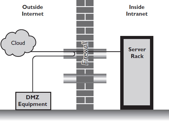
Figure 12-7 Equipment located in the DMZ may be unprotected.
NOTE ISDN bridging is another strategy for placing external calls to avoid the Internet altogether. By bridging external calls through ISDN, you can avoid the hassle and expense of firewall traversal. Of course, you’ll then take on the hassle and expense of maintaining an ISDN system in parallel to your IP-based conferencing system.
Application Layer Gateway
There are other ways for securing network communications so that conferencing systems can reach out to external participants. An Application Layer gateway (ALG) works in parallel with a firewall. The ALG examines each packet before forwarding it to the far end. In the case of NAT traversal, the ALG converts the Network Layer address information found inside each packet between the addresses acceptable by the hosts on either side of the firewall/NAT. An ALG can also support other videoconferencing-related services, such as an LDAP proxy for global address books to the endpoint. In an enterprise, an ALG must be placed at each firewall. Both SIP and H.323 Application Layer gateways are available.
Session Border Controller
A session border controller (SBC) tunnels the videoconference call through a small number of ports open on a firewall. The SBC consists of two parts: the border controller and the client.
The border controller sits outside the firewall; the client sits inside the firewall, as shown in Figure 12-8. The SBC client may exist on an endpoint or reside on another device. If the other device is a gatekeeper, it must be in routed mode, which may diminish the gatekeeper’s overall call capacity.
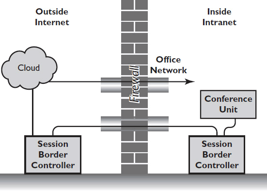
Figure 12-8 Positioning session border controllers.
When using an SBC, you typically set aside a public IP address at each site for conferencing traffic. All traffic sent to that address is automatically sent to the SBC, which forwards the call-signaling information through the few permanently open ports:
• For H.323: TCP ports 1718 to 1720 and 1731
• For SIP: TCP or UDP 5060 and 5061
The H.323 gatekeeper or SIP server then dynamically opens the other ports needed for the conference— no reservations required.
Chapter Review
Creating a conferencing system that can safely interoperate with participants on other networks is the golden ring of networked system design. It requires you to bring together all the elements of conferencing within the enterprise, understanding that outside participants will want to call from their own systems, designed for their needs, which are likely completely different from your customer’s. You must account for other conferencing protocols, including legacy systems, using gateways and other internetworking devices. You must protect the network by incorporating a firewall traversal strategy that keeps the conferencing codec from becoming an unlocked door into the network. On top of all that, you must devise a dial plan that makes it easy for users to call each other without even noticing any of those concerns. If you can master these objectives, you’ll be able to create truly priceless business tools for your customers.
Now that you’ve completed this chapter, you should be able to
• Conduct a basic needs analysis for a conferencing system
• Identify the technologies and protocols required to place a conferencing call
• Set up a network-based conference among multiple participants
• Set up a network-based conference among multiple participants in different locations
Review Questions
1. A caps exchange is when _______.
A. two networked devices tell each other what media they can send and receive
B. two networked devices format streams so the other can understand them
C. two networked devices exchange audio and video content
D. AV and IT professionals share a list of the capabilities they expect from a system
2. Identify the most common IP-based conferencing protocols. Choose all that apply.
A. Session Initiation Protocol
B. H.264
C. Real-time Stream Protocol
D. H.323
E. VoIP
3. Which of the following would not be considered part of a unified communications system?
A. Email
B. Presence
C. Videoconferencing
D. Online chat
E. Office productivity applications
4. Which network port(s) need to be opened to accommodate call setup and control for an H.323-based conferencing system?
A. Ports 5060 and 5061
B. Ports 1718 to 1720 and 1731
C. Port 80
D. Ports 458 and 554
5. A ____ ____ defines and controls how voice and video communications are managed over an IP network running an H.323 conferencing system.
A. gateway
B. gatekeeper
C. registrar server
D. proxy server
6. A(n) _______ is a device that enables online conferences among three or more endpoints.
A. telepresence system
B. SIP server
C. multipoint control unit
D. Application Layer gateway
7. If a videoconference call must travel over an IPsec VPN in order to connect remote participants, you will likely need more bandwidth because _______.
A. you never know how good a remote connection will be
B. the VPN wrapper adds overhead
C. videoconferencing wasn’t designed for VPNs
D. IPsec VPNs introduce unacceptable latency
8. Which of the following describe ways of optimizing bandwidth usage by a conferencing system if the network can’t meet the system’s bandwidth requirements? Choose all that apply.
A. Buy more bandwidth
B. Limit the number of calls placed at the same time
C. Limit the system’s allowable bit rate
D. Create rules for the H.323 gatekeeper or SIP server
9. A ____ ____ is a device that translates conferencing sessions among disparate systems that adhere to different standards.
A. gateway
B. gatekeeper
C. registrar server
D. proxy server
10. ____ ____ is a way of breaking up the frames in a videoconference when their size exceeds the equipment’s ____ _____.
A. Fragmenting; maximum transmission unit
B. Throttling; maximum transmission unit
C. Fragmenting; bit rate
D. Fragmenting; bandwidth
Answers
1. A. A caps exchange is when two networked devices tell each other what media they can send and receive.
2. A, D. Session Initiation Protocol and H.323 are common IP-based conferencing protocols.
3. E. Unified communications systems integrate various types of online communication media but not office productivity apps.
4. B. H.323-based conferencing uses ports 1718 to 1720 and 1731 for call setup and control.
5. B. A gatekeeper defines and controls how voice and video communications are managed over an IP network running an H.323 conferencing system.
6. C. A multipoint control unit enables online conferences among three or more endpoints.
7. B. If a videoconference call must travel over an IPsec VPN in order to connect remote participants, you will likely need more bandwidth because the VPN wrapper adds overhead.
8. A, B, C, D. If a network doesn’t have enough bandwidth to accommodate a conferencing system, you can buy more bandwidth, limit the number of simultaneous calls, limit the system’s allowable bit rate, and create rules for the H.323 gatekeeper of SIP server.
9. A. A gateway is a device that translates conferencing sessions among disparate systems that adhere to different standards.
10. A. Fragmenting is a way of breaking up the frames in a videoconference when their size exceeds the equipment’s maximum transmission unit.