
Chapter 8 Quality of service, charging and policy control
8.1 Quality of Service
8.1.1 General
Many mobile broadband operators aim at providing multiple services (Internet, voice, video) across their packet-switched access networks. These services will share the radio and core network resources with best effort services such as Internet browsing and e-mail download, and they all have different Quality of Service (QoS) requirements in terms of required bit rates as well as acceptable packet delays and packet loss rates. Furthermore, with mobile broadband subscriptions offering flat rate charging, high-bandwidth services such as file sharing become more common in cellular systems also. In such a multi-service scenario, it is important that EPS provides an efficient QoS solution that ensures that the user experience of each service running over the shared radio links is acceptable. Simply solving these issues through over-provisioning is not economical; the available radio spectrum is limited, and the cost of transmission capacity, including both spectrum allocations and backhaul links to potentially remote base stations, are important factors to an operator.
In addition to service differentiation, an important aspect is subscriber differentiation. The operator may provide differentiated treatment of the IP traffic for the same service depending on the type of subscription the user has. These subscriber groups can be defined in any way suitable to the operator, for example corporate vs. private subscribers, post-paid vs. pre-paid subscribers and roaming vs. non-roaming subscribers as illustrated in Figure 8.1.1.1.
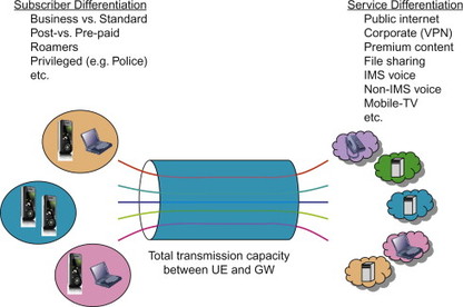
Figure 8.1.1.1 Service and subscriber differentiation.
The conclusion is that there is a need to standardize simple and effective QoS mechanisms for multi-vendor mobile broadband deployments. Such QoS mechanisms should allow the operator to enable service and subscriber differentiation and to control the performance experienced by the packet traffic of a certain service and subscriber group.
8.1.2 QoS in E-UTRAN
8.1.2.1 General
Before going into details regarding the QoS parameters and mechanisms for E-UTRAN and EPS, we will put the EPS bearer QoS concept into a wider context.
The EPS only covers QoS requirements for the traffic within the EPS, that is, between UE and PDN GW. If the service extends beyond that, QoS is maintained by other mechanisms which, for example, depend on operator deployments and service level agreements (SLAs) between network operators. This book will not go further into those aspects.
The EPS bearer service was introduced in Chapter 6. The EPS bearer represents the level of granularity for QoS control in E-UTRAN/EPS and provides a logical transmission path with well-defined QoS properties between UE and the network. The QoS concepts of the EPS bearer is then mapped to the QoS concepts of the underlying transport. For example, over the E-UTRAN radio interfaces, the EPS bearer QoS characteristics are implemented using E-UTRAN specific traffic handling mechanisms. Each EPS bearer is transported over an E-UTRAN radio bearer with the corresponding QoS characteristics. In the ‘backbone’ network between eNB, Serving GW and PDN GW, the EPS bearer QoS may be mapped to IP transport layer QoS, for example, using DiffServ. In this book we will only very briefly touch upon the lower layer QoS mechanisms. An interested reader is referred to, Dahlman (2008) for details regarding QoS mechanisms in the E-UTRAN radio layer.
8.1.2.2 Differences compared to QoS for pre-EPS GERAN/UTRAN
The QoS solutions for E-UTRAN have a few differences compared to the QoS solutions defined for GERAN/UTRAN. The two most prominent differences are described below.
Bearer control paradigm
The bearer control paradigm has changed. In GPRS Rel-6 and earlier, it was only the UE that could initiate a new bearer (i.e. a PDP context). The UE also controlled the traffic to bearer mapping information. Rel-7 was then amended with a NW-initiated procedure to establish bearers and traffic mapping information. EPS and E-UTRAN on the other hand implement a fully network-controlled bearer concept. The UE may request resources, but it is always the network that controls the EPS bearer state and the traffic to bearer mapping.
QoS parameters of a bearer
E-UTRAN also simplifies the QoS parameters that are associated with each bearer. As we will describe in more detail in later subsections, the EPS bearer is associated with two QoS parameters, a QoS class and an allocation and retention parameter. Certain EPS bearers also have associated bit rates resulting in a total of four QoS parameters for those EPS bearers.
Pre-EPS GPRS on the other hand defines a QoS concept for GERAN/UTRAN with 4 Traffic Classes and 13 different QoS Attributes. This QoS concept is often referred to as ‘release 99 QoS’ since it was introduced already for release 99 GPRS (completed in 2000). Each PDP context is assigned one of the four Traffic Classes together with values of the associated QoS Attributes. The QoS Attributes specify, for example, bit rates supported by the PDP context, the priority of the traffic, error rates, maximum transfer delay, etc. This has turned out to generate a complex system and many of the QoS Attributes are in practice not used. We will not go into any further details on Rel-99 QoS in this book. We will only discuss Rel-99 QoS on a high level to understand how GERAN/UTRAN is used together with EPS. The reader interested in more information on GRPS and Rel-99 QoS is instead referred to a book on GPRS.
Subscribed QoS parameters
In pre-EPS GPRS the subscribed QoS profile is the maximum QoS that could be allocated for each PDP context. A terminal activating multiple PDP contexts would thus have a subscribed QoS for each of them. In EPS however, the subscribed QoS stored in HSS only applies to the default bearer. There is no such thing as subscribed QoS for a dedicated bearer. Instead it is the PDN GW that determines the QoS of the dedicated bearer based on the authorized QoS received from the PCRF (Policy and Charging Rules Function). There is thus no need to have specific subscription parameters for dedicated bearers in the HSS. If the terminal is allowed to access a certain service, the PCRF will authorize the resources in the network.
Below we discuss the EPS bearer QoS in more detail. We then return to rel-99 QoS and GERAN/UTRAN to describe how QoS for GERAN/UTRAN works when GERAN/UTRAN is connected to the EPC.
8.1.2.3 QoS parameters of an EPS bearer
The basic aspects of the EPS bearer and its use for QoS purposes were already introduced in, Section 6.2. In this section we discuss the QoS parameters of the EPS bearer in more detail.
Each EPS bearer has two QoS parameters associated with it: the QoS Class Identifier (QCI) and the Allocation and Retention Priority (ARP). As we will see below, the QCI determines what user plane treatment the IP packets transported on a given bearer should receive, while the ARP specifies the control plane treatment a bearer should receive. Some EPS bearers also have associated bit rate parameters to support allocation of a guaranteed bit rate (GBR) when establishing the bearer.
As we will see below, the bearer concept and the associated QoS mechanisms provide two essential features; traffic separation and resource-based admission control. The class-based QoS concept using QCI allows the network to separate between bearers carrying real-time and bearers carrying non-real time traffic. The network can then provide the appropriate forwarding treatment for each QoS class. For the support of services that require a certain GBR, the network reserves a GBR when establishing the corresponding bearer. These bearers are subject to admission control to ensure that sufficient resources are available before allowing the GBR bearer to be set up. These mechanisms are described further below.
QoS class identifier
The EPS uses a class-based QoS concept where each EPS bearer is assigned a QCI. This QCI is a number and the numerical value in itself does not represent any QoS property. The QCI is just a pointer, or reference, to node specific parameters, which defines what packet forwarding treatment a particular bearer should receive when processed in a node (e.g. scheduling weights, admission thresholds, queue management thresholds, link layer protocol configuration, etc.). The node specific parameters for each QCI have been pre-configured by the vendor designing the node or by the operator owning the node (e.g. eNodeB).
Allocation and retention priority
The ARP is used to indicate a priority for the allocation and retention of bearers. It is typically used by the network to decide whether a bearer establishment or modification can be accepted or needs to be rejected due to resource limitations.
In the 2G/3G core network, only three ARP values are supported by the packet core network. This was considered sufficient since emergency calls run over circuit-switched voice services only and the ARP mechanism in the packet-switched domain could thus be used for commercial purposes only. However, with the packet-only EPS, emergency services have to be supported also in the packet-switched domain. Therefore the ARP definition has been more aligned with the ARP used with circuit-switched services. For example, EPS supports 15 priority values for the ARP.
In situations where resources are scarce, the network can use the ARP to prioritize establishment and modification of bearers with a high ARP over bearers with a low ARP when performing admission control; note that bearers with high ARP are assigned low ARP values, and vice versa. For example, a VoIP call for emergency services should have a higher chance of being accepted than a regular VoIP call, and should thus be assigned a high ARP. ARP also supports pre-emption of bearers. In exceptional resource limitations, the network can use the ARP to decide which bearers to drop. This could, for example, occur at handover situations. Another exceptional circumstance is disaster situations where the ARP could be used to free up capacity by dropping low ARP bearers.
GBR and non-GBR bearers
One of the properties of a bearer is the bit rates it is associated with. We distinguish between two types of bearers; GBR bearers and non-GBR bearers. A GBR bearer has, in addition to the QoS parameters discussed above, also associated bit rate allocations: the GBR and Maximum Bit Rate (MBR). A non-GBR bearer does not have associated bit rate parameters.
A bearer with an associated GBR means that a certain amount of bandwidth is reserved for this bearer, independently of whether it is utilized or not. The GBR bearer thus always takes up resources over the radio link, even if no traffic is sent. The GBR bearer should in normal cases not experience any packet losses due to congestion in the network or radio link. This is ensured since GBR bearers are subject to admission control when they are set up. A GBR bearer is only allowed by the network if there are enough resources available. The MBR limits the bit rate that can be expected to be provided by a GBR bearer. Any traffic in excess of the MBR may be discarded by a rate shaping function. EPC currently only supports the case where the MBR and GBR are equal. In a future release there may be enhancements to allow a MBR which is larger than the GBR. One of the reason for such enhancements would be to better support rate adaptive codecs where a minimum bit rate is guaranteed by the network (the GBR) while additional bandwidth may be allowed if available (the MBR).
A non-GBR bearer does not have a fixed bandwidth allocated and there is thus no guarantee for how much traffic it can carry. The non-GBR bearer may therefore experience packet loss in case of congestion. The availability of radio resources for an existing non-GBR bearer thus depends on the total load of the cell as well as the QCI of the bearer. No transmission resources are reserved for non-GBR bearers. In EPS, non-GBR bearers are rate policed on aggregate level instead of on a per bearer (or PDP context) level. Consequently, even though the non-GBR bearers do not have any associated MBR, the operator may still police the utilized bandwidth of non-GBR bearers using the Aggregate Maximum Bit Rate (AMBR) as described further below.
Whether or not a bearer should be a GBR or a non-GBR bearer typically depends on what service is carried over that bearer. The GBR bearers are typically used for those services where it is better to block a service rather than degrade already admitted services in case resources are not available. Some services such as VoIP and streaming services benefit from a constant bandwidth and a GBR value may thus be needed to ensure a satisfactory user experience. If those resources are not available, it is better to block the service. Other services, such as Internet browsing, e-mail, chat programs, etc., normally do not require a constant fixed bandwidth. Those services would typically use non-GBR bearers. Whether to use GBR or non-GBR bearers for a certain service is up to operator configuration and can, for example, be controlled using the PCC framework. The choice depends to large extent on the expected traffic load compared to the available capacity.
Standardized QCI values and corresponding characteristics
Certain QCI values have been standardized to reference specific QoS characteristics. The QoS characteristics describe the packet forwarding treatment that the traffic for a bearer receives edge-to-edge between the UE and the GW in terms of certain performance characteristics such as priority, packet delay budget and packet error loss rate. The standardized characteristics are not signalled on any interface; they should instead be understood as guidelines for the pre-configuration of node-specific parameters for each QCI. For example, the radio base station would need to be configured to ensure that traffic belonging to a bearer with a certain standardized QCI receives the appropriate QoS treatment. The goal of standardizing a QCI with corresponding characteristics is to ensure that applications/services mapped to that QCI receive the same minimum level of QoS in multi-vendor network deployments and in case of roaming. The standardized QCI characteristics are defined in clause 6.1.7 in 3GPP TS 23.203, [23.203]. A simplified description can be found in Table 8.1.2.3.1.
Table 8.1.2.3.1 Standardized QCI characteristics.
| QCI | Resource Type | Priority | Packet Delay Budget | Packet Error Loss Rate | Example Services |
| 1 | GBR | 2 | 100 ms | 10–2 | Conversational Voice |
| 2 | 4 | 150 ms | 10–3 | Conversational video (live streaming) | |
| 3 | 3 | 50 ms | 10–3 | Real-time gaming | |
| 4 | 5 | 300 ms | 10–6 | Non-conversational video (buffered streaming) | |
| 5 | Non-GBR | 1 | 100 ms | 10–6 | IMS signalling |
| 6 | 6 | 300 ms | 10–6 | Video (buffered streaming)TCP-based (e.g. www, e-mail, chat, ftp, p2p file sharing, progressive video, etc.) | |
| 7 | 7 | 100 ms | 10–3 | Voice, video (live streaming) interactive gaming | |
| 8 | 8 | 300 ms | 10–6 | Video (buffered streaming) TCP-based (e.g. www, e-mail, chat, ftp, p2p filesharing, progressive video, etc.) | |
| 9 | 9 | 300 ms | 10–6 | Video (buffered streaming) TCP-based (e.g. www, e-mail, chat, ftp, p2p filesharing, progressive video, etc.) |
The QCI values 1–4 are allocated for traffic that require dedicated resource allocation for a GBR, while values 5–9 are not associated with GBR requirements. Each standardized QCI is associated with a priority level, where priority level 1 is the highest priority level. The Packet Delay Budget can be described as an upper bound for the time that a packet may be delayed between the UE and the PCEF (Policy and Charging Enforcement Function). The Packet Error Loss Rate can in a simplified manner be described as an upper bound for the rate of non-congestion related packet losses.
Note that the description above gives a very simplified definition of the standardized QCIs, hiding many of the details. The purpose is to give the general reader a basic view of the topic. The interested reader should consult, [23.203] for the complete definitions.
Apart from these standardized QCI, also non-standardized QCIs may be used. In this case it is the operators and/or vendors who define what node-specific parameters are used for a given QCI.
8.1.2.4 APN-AMBR and UE-AMBR
In addition to the bit rate parameters associated with each GBR bearer, EPS also defines the AMBR parameters that are associated with non-GBR bearers. These parameters are not specific to each non-GBR bearer, but rather define a total bit rate that a subscriber is allowed to consume for an aggregate of non-GBR bearers. The bit rate consumed by the GBR bearers does not count towards the AMBR. Two variants of the AMBR are defined; the APN-AMBR and the UE-AMBR.
One reason for why an aggregate rate policing of non-GBR bearers is preferable over a per-bearer policing is that network planning becomes easier. With a subscribed per-bearer MBR (as in GPRS) it is difficult to estimate the total bit rate the subscribers will use. Also, an AMBR can provide a more understandable subscription for the end-user compared to an MBR that is per bearer.
The APN-AMBR defines the total bit rate that is allowed to be used for all non-GBR bearers associated with a specific APN. This parameter is defined as part of a user’s subscription but may be overridden by the PCRF. The APN-AMBR limits the total non-GBR traffic for an APN, independent of the number of PDN connections and non-GBR bearers that are opened for that APN. In other words, if a user has multiple PDN connections for the same APN, they all share the same APN-AMBR. For example, if an operator provides an APN for Internet access, the operator may then limit the total bandwidth for that APN and thus prevent the UE from increasing its accessible bandwidth by just opening new PDN connections to the same APN. This is different from 2G/3G core network where the subscribed QoS is defined per PDP context. The APN-AMBR is enforced by the PDN GW.
The UE-AMBR is defined per subscriber and defines the total bit rate allowed to be consumed for all non-GBR bearers of a UE. The subscription profile contains a subscribed UE-AMBR. However, the actual UE-AMBR value that is enforced by the network is set as the minimum of the subscribed UE-AMBR and the sum of the APN-AMBR of all active APNs (i.e. all APNs for which the UE has active PDN connections). The UE-AMBR is enforced by the eNB.
Different AMBR values are defined for uplink and downlink directions. There are thus in total four AMBR values defined: UL APN-AMBR, DL APN-AMBR, UL UE-AMBR and DL UE-AMBR.
The UE-AMBR and APN-AMBR are not dependent on each other and an operator may choose to apply either UE-AMBR or APN-AMBR (or both). The enforcement of the UE-AMBR and APN-AMBR are two tools for the operator to realize the business model. The UE-AMBR may be used to put upper limits on a subscription or to limit the total amount of traffic in the network. The APN-AMBR on the other hand is more related to, for example, Service Level Agreements with external PDNs or subscriptions related to specific APNs.
8.1.2.5 User plane handling
Some aspects of the user plane handling of EPS bearers were introduced already in Chapter 6. In particular it was there shown how packet filters in the UE and the GW are used to determine which IP flows shall be carried over a certain EPS bearer. Now, after the description of the mechanisms available for QoS control in E-UTRAN, it is again useful to look at user plane handling and how the QoS functions and QoS parameters described above are allocated to different nodes in the network. Figure 8.1.2.5.1 indicates different user plane QoS functions for E-UTRAN/EPS.
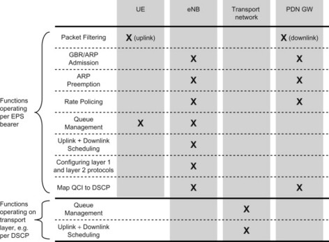
Figure 8.1.2.5.1 Overview of user plane QoS functions for E-UTRAN/EPS. The functional allocation is for GTP-based S5/S8. For PMIP-based S5/S8, the bearer-related functions are moved to the Serving GW.
The UE and GW (PDN GW for GTP-based S5/S8 and Serving GW for PMIP-based S5/S8) carry out uplink and downlink packet filtering respectively in order to map the packet flows on to the intended bearer.
The GW and the eNB can implement functions related to admission control and preemption handling (i.e. congestion control) in order to allow these nodes to limit and control the load put on them. These functions can take the ARP value as an input in order to differentiate the treatment of different bearers in these functions, as described in the ARP section above.
The GW and eNB further implement functions related to rate policing. The goal of these functions is twofold: to protect the network from becoming overloaded and to ensure that the services are sending data in accordance to the specified maximum bit rates (AMBR and MBR). For the non-GBR bearers, the PDN GW performs rate policing based on the APN-AMBR value(s) for both uplink and downlink traffic, while the eNB performs rate policing based on the UE-AMBR value for both uplink and downlink traffic. For GBR bearers, MBR policing is carried out in the GW for downlink traffic and in the eNB for up-link traffic.
In order to distribute radio network resources (radio and processing resources) between the established bearers, the eNB implements uplink and downlink scheduling functions. The scheduling function is to a large extent responsible for fulfilling the QoS characteristics associated to the different bearers.
The eNB is responsible for configuring the lower layer (layers 1 and 2) protocols of the radio connection of the bearer in accordance to the QoS characteristics associated with the bearer. Among others, this includes configuring the error-control protocols (modulation, coding, and link layer retransmissions) so that the QoS characteristics, packet delay budget and packet error loss are fulfilled. For more details on QoS handling in E-UTRAN, see Dahlman (2008).
On the transport level, that is, the basic IP transport between EPC network entities (including intermediate transport entities in the packet cores such as regular IP routers), are not aware of the EPS bearers and instead queue management and packet forwarding treatment is done according to a transport layer mechanism such as DiffServ. The EPC entities map the QCI of the EPS bearer on to DiffServ Code Point (DSCP) values that are used by the transport network.
It should be noted that there are also service aware QoS control functions operating on a finer granularity than the EPS bearer. These functions are defined as part of the Policy and Charging Control (PCC) architecture and are described in the PCC section of this chapter.
8.1.3 Interworking with GERAN/UTRAN
As mentioned above, E-UTRAN and the EPS have a different QoS control architecture compared to GERAN/UTRAN access – the pre-EPS QoS model is often referred to as the release 99 QoS, or Rel-99 QoS for short. When connecting GERAN/UTRAN accesses to EPS, via a S4-based SGSN, there are in theory two main alternatives for how to handle QoS in GERAN/UTRAN:
-
Implement the EPS QoS solutions also in GERAN/UTRAN access. This would, for example, imply that the QCI would be used for each PDP context, instead of the GERAN/UTRAN (Rel-99) QoS profile. This has the benefit that 3GPP family of accesses in EPS uses the same QoS parameters. It should however be noted that the GERAN/UTRAN radio interface has to be backwards compatible with the Rel-99 QoS scheme and PDP context procedures in order to allow pre-EPS terminals to connect. An EPS-based GERAN/UTRAN network would thus anyhow need to implement Rel-99 based QoS.
-
Keep the existing Rel-99 QoS and PDP context procedures for GERAN/UTRAN. This would imply the least changes to the current GERAN/UTRAN radio interface, but there would be a need to specify a mapping to EPS-based QoS solutions and bearer procedures.
3GPP decided for the second alternative. The main motivation was that this was the simplest option that was also backwards compatible with pre-EPS terminals.
Please see the bearer section of Chapter 6 for a description of the interworking between PDP context and EPS bearer procedures. In this section we look at the corresponding mapping between QoS parameters. Depending on scenario, different network entities need to perform mapping between QoS parameters associated with EPS bearer and the QoS parameters associated with the PDP context. The detailed mapping between the EPS QoS parameters and the rel-99 QoS parameters is defined in Annex E of 3GPP TS 23.401, [23.401] and briefly described below:
-
The ARP for a PDP context can take three possible values, while the ARP for an EPS bearer can take 15 possible values. The mapping between PDP context ARP values and EPS bearer ARP values is a one-to-many mapping. The exact scheme for which range of EPS bearer ARP values is mapped to an ARP value of a PDP context is not standardized but can be configured by each operator.
-
The GBR and MBR values are mapped one-to-one (for GBR bearers only).
-
The MBR for PDP contexts without GBR is mapped to/from APN-AMBR.
-
The mapping between the standardized QCIs and the rel-99 Traffic Class and QoS Attributes is described in Annex E of 3GPP TS 23.401. Only a subset of the Rel-99 QoS Attributes are specified by the mapping. The setting of the values of the other rel-99 QoS Attributes is not specified by the standard and is instead based on operator policy pre-configured in the SGSN.
-
In the first release of EPS (3GPP Rel-8), UE-AMBR is only used in E-UTRAN and has no counterpart when using 2G/3G. In the next release (Rel-9), UE-AMBR is applied also for 2G/3G accesses.
8.1.4 QoS aspects when interworking with other accesses
So far we have been considering QoS aspects related to the 3GPP family of accesses. EPS does however support interworking and mobility with other accesses as well, defined by other standardization bodies. Each such access may have its own set of QoS mechanisms and QoS parameters, as defined by the relevant standardization body. It is not possible within this book to go through each access and discuss the access-specific QoS solutions. There are, however, a few aspects that are either independent of access or related to the interworking between EPS and the access-specific QoS mechanism.
One QoS parameter that is common to all accesses is the APN-AMBR as described in the APN-AMBR section above. The APN-AMBR is enforced by the PND GW and can be enforced independent of which access the UE may be using.
Other access independent parameters are the QCI and ARP. As described above the QCI and ARP are parameters of the EPS bearer when using 3GPP family of accesses. As we will see in the next section on PCC, the PCC architecture also uses QCI and ARP, but as access independent parameters. When interworking with other accesses, these parameters are mapped by each individual access to access-specific parameters and mechanisms.
8.2 Policy and Charging Control
8.2.1 Introduction
PCC provides operators with advanced tools for service-aware QoS and charging control. In wireless networks, where the bandwidth is typically limited by the radio network, it is important to ensure an efficient utilization of the radio and transport network resources. Furthermore, different services have very different requirements on the QoS, which are needed for the packet transport. Since a network in general carries many different services for different users simultaneously, it is important to ensure that the services can co-exist and that each service is provided with an appropriate transport path.
PCC enables a centralized control to ensure that the service sessions are provided with the appropriate transport, for example, in terms of bandwidth and QoS treatment. The PCC architecture enables control of the media plane for both the IP Multimedia Subsystem (IMS) and non-IMS services. Furthermore, PCC also provides the means to control charging on a per-service basis.
When in 3GPP access, bearer procedures are available for QoS management in the access. While the EPS bearer and PDP context procedures are specific to the 3GPP family of accesses, corresponding QoS procedures exist for many other accesses as well. In this section we focus on how the operator can control those the QoS procedures and the charging mechanisms used for each service session.
When it comes to PCC, the term ‘bearer’ is used in a more generic fashion to denote an IP transmission path with well-defined characteristics (e.g. capacity, delay and bit error rate). This allows us to use the bearer terminology in an access agnostic fashion, independent of the details for how this transmission path is created or how QoS is managed for each access technology.
The term ‘service session’ is also important here. The bearer concept handles traffic aggregates, that is, all conformant traffic that is transported over the same bearer receives the same QoS treatment. This means that multiple service sessions transported over the same bearer will be treated as one aggregate. These bearer concepts still apply when PCC is used. As we will see however, PCC adds a ‘service aware’ QoS and charging control mechanism that in certain aspects is more fine grained; that is, it operates on a per-service session level rather than on a per-bearer level.
The PCC architecture for EPS is an evolution of the PCC architecture defined in 3GPP Rel-7. PCC has nevertheless evolved significantly from 3GPP Rel-7 in order to support new features in EPS, such as multiple access technologies, roaming and multi-access mobility. The goal in 3GPP has been to define an access-agnostic policy control framework, and as such, make it applicable to a number of accesses such as E-UTRAN, UTRAN, GERAN, HRPD and WiMAX. Furthermore, the introduction of a complete roaming model for PCC allows operators to have the same dynamic PCC, and provide the same access to services independently of whether a user is making this access through a gateway in their home or visited network.
It is also worth mentioning that standardization bodies standardizing other access technologies for fixed or wireless access have also created policy control specifications targeting their particular access technologies. When it comes to wireless accesses such as WiMAX and HRPD, an alignment towards a common policy control architecture based on 3GPP PCC has already been materialized with the EPS. For the fixed accesses, in particular related to the standardization work being done in ETSI TISPAN and in Broadband Forum (BBF) the work towards alignment and/or interworking has not come as far as for the wireless accesses.
8.2.2 The PCC Architecture
The basic aspects of the EPS architecture, including the PCC aspects, were introduced already in Chapter 3. In this section we give a more in-depth description as well as describe the basic concepts and functions of PCC.
The reference network architecture for PCC in EPS is shown in Figure 8.2.2.1. The functional entities that are part of the PCC architecture are briefly described below.
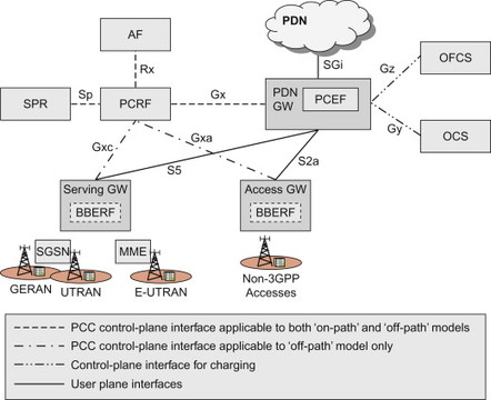
Figure 8.2.2.1 3GPP Rel-8 PCC non-roaming architecture for EPS. Note that only a subset of the EPS reference points and EPS network entities are shown.
The Application Function (AF) interacts (or intervenes) with applications or services that require dynamic PCC. Typically the application level signalling for the service passes through, or is terminated, in the AF. The AF extracts session information from the application signalling and provides this to the PCRF over the Rx reference point. The AF can also subscribe to certain events that occur at the traffic plane level (i.e. events detected by either PCEF or BBERF (Bearer Binding and Event Reporting Function)). Those traffic plane events include events such as IP session termination or access technology type change. When the AF has subscribed to a traffic plane event, the PCRF will inform the AF of its occurrence. The term ‘Application Function’ is a generic term used by PCC for this entity, and in practice the AF functionality is contained within a specific network entity depending on the type of service. For the IMS, the AF corresponds to the P-CSCF. For a non-IMS service, the AF could, for example, be a video streaming server.
The Subscription Profile Repository (SPR) contains subscription information, such as user specific policies and data.
The Online Charging System (OCS) is a credit management system for pre-paid charging. The PCEF interacts with the OCS to check out credit and report credit status.
The Offline Charging System (OFCS) is used for offline charging. It receives charging events from the PCEF and generates Charging Data Records (CDRs) that can be transferred to the billing system.
The PCRF is the policy control function of PCC. It receives session information over Rx as well as information from the access network via the Gx. If a BBERF is used (see below), the PCRF also receives information via Gxa/Gxc reference points. (Gxb was defined between ePDG and PDN GW but is not used in the first release of EPS.) The PCRF may as well receive subscription information from the SPR. The PCRF takes the available information, as well as configured operator policies, into account and creates service-session level policy decisions. The decisions are then provided to the PCEF and the BBERF. Another task of the PCRF is to forward event reports between the BBERF, the PCEF and the AF.
The PCEF enforces policy decisions (e.g. gating, maximum bit rate policing) received from the PCRF and also provides the PCRF with user- and access-specific information over the Gx reference point. The PCEF may also perform measurements of user plane traffic (e.g. user plane traffic volume and/or time duration of a session). It reports usage of resources to the OFCS and interacts with the OCS for credit management.
In the PCC architecture for EPS, there are two main architecture alternatives; with and without BBERF in the Access GW (e.g. Serving GW or HSGW). In common language the two alternatives are referred to as ‘off-path’ and ‘on-path’ models respectively. The BBERF supports a subset of the functions supported by the PCEF. The details regarding the BBERF and the two architecture alternatives are discussed further below.
8.2.2.1 Multi-access and the off-path PCC model
As described in, Section 6.4, EPS supports different mobility protocols depending on which access technology is used. For the 3GPP family of accesses (GERAN, UTRAN and E-UTRAN) the GTP or PMIPv6 may be used on the S5/S8 reference points. For connecting other accesses to EPC, it is possible to use PMIPv6, DSMIPv6, Mobile IPv4 (MIPv4) on S2a/b/c reference points. These different protocols have different properties when it comes to how the EPS bearers are implemented. These differences result in different requirements on PCC.
When GTP is used between the Serving GW and the PDN GW, the bearers are terminated in the PDN GW and the PDN GW can thus use the bearer procedures to control the EPS bearers. We refer to this model as the ‘on-path’ model because the QoS/bearer signalling takes place (using GTP) on the same ‘path’ as the user plane. In this model, the PCRF controls the QoS by providing the QoS policy information to the PCEF via the Gx reference point. The BBERF and Gxa/Gxc have no role here and are thus not used at all in the ‘on-path’ model.
When a Mobile IP-based protocol, such as PMIP or DSMIPv6, is used towards the PDN GW, the bearers and QoS reservation procedures are terminated closer to the (radio) access network and the PDN GW has thus no knowledge about bearers. For 3GPP family of accesses, the bearers only extend between the UE and the Serving GW. Between the Serving GW and the PDN GW there is no notion of EPS bearers. See the bearer section in Chapter 6 for illustrations. For other accesses, the bearers and QoS reservation procedures (if existing) extend between the UE and an ‘access GW’ in the access network. In this case, the PDN GW only handles mobility signalling towards the access network and the UE, not any QoS signalling. Therefore the PDN GW cannot control the QoS using bearer procedures and it is not sufficient for the PCRF to provide the QoS information to the PCEF. The PCRF has to provide the QoS info to the entity where the bearers are terminated. For this purpose, the BBERF and the Gxa/Gxc reference points are introduced.
When it comes to other functions of PCC, not related to where bearers are terminated, there is in most cases no difference between the ‘on-path’ and ‘off-path’ models. For example, the service aware charging functionality is always located in the PCEF. Further details on the functional content of PCEF and BBERF can be found in later subsections.
For EPS, the PCEF is always located in the PDN GW. The BBERF location, however, depends on the particular access technology. For example, for the 3GPP family of accesses, the BBERF (if applicable) is located in the Serving GW, whereas for eHRPD access the BBERF is located in the HSGW. Since the PDN GW is the mobility anchor for the UE, the same PCEF is kept during the whole IP session. The BBERF allocated for a UE may however change due to the mobility of the UE. For example, the Serving GW may change as the UE moves within the 3GPP accesses. The BBERF location will also change when the UE moves between 3GPP and other access technologies. Support for BBERF relocation is thus an inherent part of the off-path PCC architecture for EPS.
8.2.3 Basic PCC concepts
8.2.3.1 PCC
As the name suggests, the purpose of PCC is policy and charging control.
Policy control is a very generic term and in a network there are many different policies that could be implemented, for example, policies related to security, mobility, use of access technologies etc. When discussing policies, it is thus important to understand the context of those policies. When it comes to PCC, policy control refers to the two functions gating control and QoS control:
-
Gating control is the capability to block or to allow IP packets belonging to IP flow(s) for a certain service. The PCRF makes the gating decisions which are then enforced by the PCEF. The PCRF could, for example, make gating decisions based on session events (start/stop of service) reported by the AF via the Rx reference point.
-
QoS control allows the PCRF to provide the PCEF with the authorized QoS for the IP flow(s). The authorized QoS may, for example, include the authorized QoS class and the authorized bit rates. The PCEF or BBERF enforces the QoS control decisions by setting up the appropriate bearers. The PCEF also performs bit rate enforcement to ensure that a certain service session does not exceed its authorized QoS.
Charging Control includes means for both offline and online charging. The PCRF makes the decision on whether online or offline charging shall apply for a certain service session, and the PCEF enforces that decision by collecting charging data and interact with the charging systems. The PCRF also controls what measurement method applies, that is, whether data volume, duration, combined volume/duration or event-based measurement is used. Again it is the PCEF that enforces the decision by performing the appropriate measurements on the IP traffic passing through the PCEF.
With online charging, the charging information can affect, in real-time, the services being used and therefore a direct interaction of the charging mechanism with the control of network resource usage is required. The online credit management allows an operator to control access to services based on credit status. For example, there has to be enough credit left with the subscription in order for the service session to start or an ongoing service session to continue. The OCS may authorize access to individual services or to a group of services by granting credits for authorized IP flows. Usage of resources is granted in different forms. The OCS may, for example, grant credit in the form of certain amount of time, traffic volume or chargeable events. If a user is not authorized to access a certain service, for example, in case the pre-paid account is empty, then the OCS may deny credit requests and additionally instruct the PCEF to redirect the service request to a specified destination that allows the user to re-fill the subscription.
PCC also incorporates service-based offline charging. With offline charging, the charging information is collected by the network for later processing and billing. Therefore, the charging information does not affect, in real-time, the service being used. Since billing is taking place after the service session has completed, for example, via a monthly bill, this functionality does not provide any means for access control in itself. Instead policy control must be used to restrict access and then service-specific usage may be reported using offline charging.
Online and offline charging may be used at the same time. For example, even for billed (offline charged) subscriptions, the online charging system may be used for functionality such as Advice of Charge. Conversely, for prepaid subscribers, the offline charging data generation may be used for accounting and statistics.
8.2.3.2 PCC decisions, the PCC rule and the QoS rule
The PCRF is the central entity in PCC making PCC decisions. The decisions can be based on input from a number of different sources, including:
-
Operator configuration in the PCRF that defines the policies applied to given services.
-
Subscription information/policies for a given user, received from the SPR.
-
Information about the service received from the AF.
-
Information from the access network about what access technology is used, etc.
The PCRF provides its decisions in the form of so called ‘PCC rules’. The PCRF also provides a subset of the information in the so called ‘QoS rules’ to the BBERF if the ‘off-path’ model is used. In this section we first describe the main content of the PCC rules and then the subset of information contained in a QoS rule.
A PCC rule contains a set of information that is used by the PCEF and the charging systems. First of all it contains information (in a so called ‘Service Data Flow (SDF) template’) that allows the PCEF to identify the IP packets that belong to the service session. All IP packets matching the packet filters of a SDF template are designated a SDF. The filters in a SDF template contain a description of the IP flow and typically contain the source and destination IP addresses, the protocol type used in the data portion of the IP packet, as well as the source and destination port numbers. These five parameters are often referred to as the IP 5-tuple. It is also possible to specify other parameters from the IP headers in the SDF template. The PCC rule also contains the gating status (open/closed) as well as QoS and charging-related information for the SDF. The QoS information for a SDF includes the QCI, MBR, GBR and ARP. The definition of the QCI is the same as that described in the QoS section in Chapter 8 for the EPS bearer and the reader is referred to that section for a more thorough description of those parameters. However, one important aspect of the QoS parameters in the PCC rule is that they have a different scope than the QoS parameters of the EPS bearer. The QoS and charging parameters in the PCC rule apply to the SDF. More precisely, the QCI, MBR, GBR and ARP in the PCC rule apply to the IP flow described by the SDF template, while the QCI, MBR, GBR and ARP discussed in Chapter 8 applies for the EPS bearer. A single EPS bearer may be used to carry traffic described by multiple PCC rules, as long as the bearer provides the appropriate QoS for the service data flows of those PCC rules. We will further below discuss more on how PCC rules and SDFs are mapped to bearers. Table 8.2.3.2.1 lists a subset of the parameters that can be used in a PCC rule sent from PCRF to PCEF. For a full list of parameters, please see 3GPP TS 23.203 and 3GPP TS 29.212 [, 23.203, 29.212].
Table 8.2.3.2.1 A subset of the elements that may be included in a dynamic PCC rule.
| Type of element | PCC rule element | Comment |
| Rule identification | Rule identifier | It is used between PCRF and PCEF for referencing PCC rules |
| Information related to Service Data Flow detection in PCEF and BBERF | Service Data Flow Template | List of packet filters for the detection of the service data flow |
| Precedence | Determines the order, in which the service data flow templates are applied at PCEF | |
| Information related to policy control (i.e. gating and QoS control) | Gate status | Indicates whether a SDF may pass (gate open) or shall be discarded (gate closed) |
| QoS Class Identifier (QCI) | Identifier that represents the packet forwarding behaviour of a flow. | |
| UL and DL Maximum bit rates | The maximum uplink (UL) and downlink (DL) bitrates authorized for the service data flow | |
| UL and DL Guaranteed bit rates | The guaranteed uplink (UL) and downlink (DL) bitrates authorized for the service data flow | |
| ARP | The Allocation and Retention Priority for the service data flow | |
| Information related to charging control | Charging key | The charging system uses the charging key to determine the tariff to apply for the service data flow |
| Charging method | Indicates the required charging method for the PCC rule | |
| Values: online, offline or no charging | ||
| Measurement method | Indicates whether the SDF data volume, duration, combined volume/duration or event shall be measured |
Text copied from 23.203.
The same standardized QCI values and QCI characteristics outlined in Section 8.1 applies when QCI is used in the PCC rule. The standardized QCI and corresponding characteristics is independent of the UE’s current access. The access network receiving the PCC rule will thus map the QCI value of the PCC rule on to any access-specific QoS parameters that apply in that access. This is further elaborated below.
The discussion so far has assumed a case where the PCRF provides the PCC rules to the PCEF using Gx. These rules, which are dynamically provided by the PCRF, are denoted ‘dynamic PCC rules’. There is however also a possibility for the operator to configure PCC rules directly into the PCEF. Such rules are referred to as ‘pre-defined PCC rules’. In this case the PCRF can instruct the PCEF to activate such pre-defined rules by referring to a PCC rule identifier. While the packet filters in a dynamic PCC rule are limited to the IP header parameters (the IP 5-tuple and other IP header parameters), filters of a PCC rule that is pre-defined in the PCEF may use parameters that extend the packet inspection beyond the IP 5-tuple. Such filters are sometimes referred to as Deep Packet Inspection (DPI) filters and they are typically used for charging control where more fine grained flow detection is desired. The definition of filters for pre-defined rules is not standardized by 3GPP.
As described above, in case the ‘off-path’ model applies the PCRF need to provide the QoS information to the BBERF via the Gxa/Gxc reference points. The QoS information provided to the BBERF is the same as is present in the corresponding PCC rule. However, since the BBERF only needs a subset of the information available in a PCC rule, the PCRF does not send the full PCC rule to the BBERF. Instead the PCRF generates a so called ‘QoS rule’ with information from the corresponding PCC rule. The QoS rules contain the information needed for the BBERF to ensure that bearer binding (see below) can be performed. The QoS rules thus contain the information needed to detect the SDF (i.e. SDF template and precedence) as well as the QoS parameters (e.g. QCI and bit rates). QoS rules do not contain any charging-related information.
8.2.3.3 Use cases
As a result of the interactions with the PCRF, the PCEF and BBERF perform several different functions. In this subsection we present two use cases in order to get an overview of the dynamics of PCC and how PCC interacts with the application level as well as the access network level. Some of the aspects brought up in the use cases will actually be discussed in more detail later. The intent with placing the use cases first is that a basic overview of the procedures described in the use cases should simplify the understanding of the PCC aspects being discussed in the later subsections.
The first use case is intended to illustrate a service session setup using ‘on-path’ PCC, network-initiated QoS control and online charging (Figure 8.2.3.3.1).
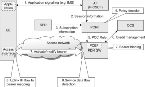
Figure 8.2.3.3.1 High level use case for PCC in the EPS for the ‘on-path’ model and NW-initiated bearer procedures.
The first use case is described below:
-
The subscriber initiates a service, for example, an IMS voice call, and performs end-to-end application session signalling that is intercepted by the AF (P-CSCF in the IMS case). In the IMS case, the application signalling is using the Session Initiation Protocol (SIP). A description of the service is provided as part of the application signalling. In IMS, the Session Description Protocol (SDP) is used to describe the sessions.
-
Based on service description information contained in the application signalling, the AF provides the PCRF with the service-related information over the Rx interface. The session information is mapped at the AF from a SDP (e.g. SIP/SDP for IMS) into information elements in the Rx messages to the PCRF. This information typically includes QoS information (type of service, bit rate requirements) as well as traffic parameters (e.g. the IP 5-tuple) that allow identification of the IP flow(s) corresponding to this service session.
-
The PCRF may request subscription-related information from the SPR. (The PCRF may have requested subscription information earlier but it is shown at this step for illustrative purposes.)
-
The PCRF takes the session information, operator-defined service policies, subscription information and other data into account when building policy decisions. The policy decisions are formulated as PCC rules.
-
The PCC rules are sent by the PCRF to the PCEF. The PCEF will enforce the policy decision according to the received PCC rule. All user plane traffic for a given subscriber and IP connection pass through the network entity where the PCEF is located. For EPS, the PCEF is located in the PDN GW.
-
If the PCC rule specified that online charging shall be used for this PCC rule, the PCEF contacts the OCS via the Gy reference point to request credit according to the measurement method specified in the PCC rule.
-
The PDN GW (PCEF) installs the PCC rules and performs bearer binding to ensure that the traffic for this service receives appropriate QoS. This may result in the establishment of a new bearer, or a modification of an existing bearer. More details on bearer binding is provided further below.
-
The media for the service session is now being transported across the network and the PCEF performs SDF detection to detect the IP flow for this service. This IP flow is transported over the appropriate bearer. Further details on SDF detection can be found below.
The second example intends to illustrate the same basic use case but in a different network scenario using ‘off-path’ PCC, UE-initiated QoS control and offline charging. With UE-initiated QoS control, the UE and the network rely on UE-initiated triggers that start the bearer operations for this application. More discussion on UE- and network-initiated QoS control principles can be found below. Since offline charging is used, the PDN GW (PCEF) does not perform credit-based access control. The interactions with the charging system are therefore not shown in the use case.
It can be noted that the first three steps in the second use case are the same as in the first use case. These steps concern the application level signalling and the Rx signalling. This signalling is not dependent on access network properties, such as whether on-path or off-path PCC is used or whether UE-initiated or NW-initiated procedures are used. It is only the handling in the PCRF and in the access network that differ depending on PCC architecture model and UE/NW-trigger of bearer procedures.
The use case with ‘off-path’ model and UE-initiated procedures is described below (Figure 8.2.3.3.2). The first three steps are included in shortened form below. The full description can be found in the first use case.
-
The subscriber initiates a service, for example, an IMS voice call, and performs IMS session signalling via the AF.
-
Based on service description information contained in the application signalling, the AF provides the PCRF with the service-related information over the Rx interface.
-
The PCRF may request subscription-related information from the SPR.
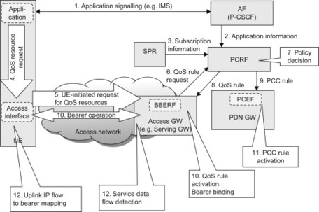
Figure 8.2.3.3.2 High level use case for PCC in the EPS for the ‘off-path’ model and UE-initiated bearer procedures.
The difference between UE-initiated and NW-initiated procedures will now become evident. In the first use case, the PCRF ‘pushed’ the rules to the PDN GW, and the PDN GW initiated bearer procedures to ensure that the service receives the appropriate QoS treatment. In the second use case, the PCRF instead waits until the request from the UE triggers a ‘pull’ of rules from the PCRF. This is described in the steps below:
-
The application in the UE makes a (internal) request for the access interface to request the QoS resources needed by the newly started application.
-
The UE sends a request to the network for QoS resources for this service. The UE includes the QoS class and packet filters associated with the service. The UE may also include a request for a certain GBR. The exact details regarding this request depend on which access technology the UE is using. For E-UTRAN, the UE would send a UE-requested bearer resource modification. For GERAN/UTRAN access, the UE would make a secondary PDP context activation or modification request. Other accesses may provide similar access-specific signalling.
-
Since off-path PCC is used, the BBERF initiates a PCRF interaction when receiving the request sent by the UE. (For comparison; in the on-path model, the request from the UE would have been forwarded from the Serving GW to the PDN GW, and the PDN GW would have sent a request for PCC rules to the PCRF.)
-
Similar to the first use case (step 4 in the first use case), the PCRF takes the session information, operator-defined service policies, subscription information and other data into account when building policy decisions. The policy decisions are formulated as PCC rules. Since off-path PCC is used, the PCRF also derives QoS rules based on the PCC rules.
-
The PCRF sends the QoS rules to the BBERF.
-
The PCRF sends the corresponding PCC rules to the PCEF.
-
The BBERF (e.g. Serving GW) installs the QoS rules and performs bearer binding to ensure that the traffic for this service receives appropriate QoS. This may result in the establishment of a new bearer, or the modification of an existing bearer.
-
The PDN GW (PCEF) installs the PCC rules. The PCEF performs gating, bit rate enforcement and service level charging as defined by the PCC rule.
-
The media for the service session is now being transported across the network. The UE uses uplink packet filters to determine which bearer shall carry the uplink traffic. Both the BBERF and PCEF perform SDF detection to detect the IP flow for this service. The BBERF forwards the downlink traffic over the appropriate bearer.
Note that the above two use case examples are not exhaustive in any sense. There are many other scenarios and configurations. For example, for services that do not provide an AF or Rx interface, it is still possible to use PCC. In that case step 2 of the second use case would be missing and the PCRF would authorize PCC/QoS rules based on pre-configured policies without access to dynamic session data.
8.2.3.4 Bearer binding
The PCC rule needs to be mapped to a corresponding bearer in the access network to ensure that the packets receive the appropriate QoS treatment. This mapping is one of the central components of PCC. The association between a PCC/QoS rule and a bearer is referred to as bearer binding. The bearer binding is done by the Bearer Binding Function (BBF) which is located either in the PCEF (for on-path) or in the BBERF (for off-path). When the PCEF (or BBERF) receives new or modified PCC or QoS rules, the BBF evaluates whether or not it is possible to use the existing bearers. If one of the existing bearers can be used, for example, if a bearer with the corresponding QCI and ARP already exists, the BBF may initiate bearer modification procedures to adjust the bit rates of that bearer. If it is not possible to use any existing bearer and NW-initiated bearer procedures are used, the BBF initiate the establishment of a suitable new bearer. In particular, if the PCC rule contains GBR parameters, the BBF must also ensure the availability of a GBR bearer which can accommodate the traffic for that PCC rule. If NW-initiated bearer procedures are used, the BBF triggers resource reservation in the access network to ensure that the authorized QoS of the PCC rule can be provided. Further details on the bearer concept can be found in Chapter 6.
For EPS and in case the UE is using 3GPP accesses, the BBF uses the EPS bearer procedures when activating the PCC/QoS rules. Other accesses interworking with EPS may have other, access specific, QoS signalling mechanisms. It is the task of the BBF to interact with the appropriate QoS procedures depending on access technology. In order to set up the right QoS resources in the access, the PCEF/BBERF not only need to invoke the appropriate QoS procedures but may also need to map the QoS parameters. In particular the BBF must map the QCI of the PCC/QoS rule, which is an access independent parameter, to access specific QoS parameters. For the 3GPP family of accesses in EPS this is simple since the QCI is used also as a QoS parameter for the EPS bearers. For other accesses, the mapping may involve a ‘translation’ from the QCI in the PCC/QoS rule to other access specific QoS parameters that are used in that particular access.
8.2.3.5 Service Data Flow detection
Once the service session is set up and the media traffic for the service is flowing, the PCEF and the BBERF use the packet filters of installed PCC and QoS rules to classify IP packets to authorized SDFs. This process is referred to as SDF detection. Each filter in the SDF filter is associated with a precedence value. The PCEF (or BBERF) matches the incoming packets against the available filters of the installed rules in order of precedence. The precedence is important if there is an overlap between filters in different PCC rules. One example of such overlap is a PCC rule which contains a wildcard filter that overlaps with more narrowly scoped filters in other PCC rules. In this case, the wildcard filter should be evaluated after the more narrowly scoped filters; otherwise the wildcard filter will cause a match before the PCEF/BBERF even tries the narrowly scoped filters. If a packet matches a filter, and the gate of the associated rule is open, then the packet may be forwarded to its destination. For the downlink part, the classification of an IP-packet to an SDF also determines which bearer should be used to transfer the packet (Figure 8.2.3.5.1). See also, Section 6.3 for more details on bearers and how packet filters are used to direct packets on to the right bearer.
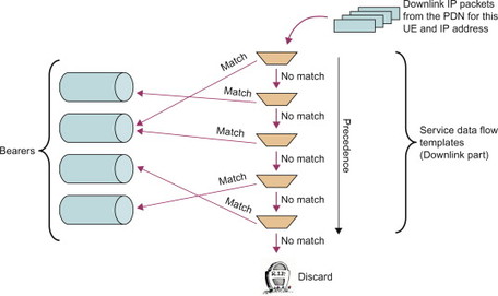
Figure 8.2.3.5.1 Example of SDF detection and mapping to bearers for downlink traffic.
An additional aspect related to SDF detection occurs when DSMIPv6 is used as a mobility protocol. In that case the user plane traffic is tunnelled between UE and PDN GW, and thus also when passing through the BBERF; see Section 11.3 for more details on DSMIPv6. Since the packet filters of the PCC rule refer to un-tunnelled packet flows, the BBERF has to ‘look inside’ the DSMIPv6 tunnel to be able to apply the packet filters in the SDF template. This is something often referred to as ‘tunnel look-through’ and is illustrated in Figure 8.2.3.5.2. The outer tunnel header is determined when the DSMIPv6 tunnel is established by the UE and the PDN GW. Information about the tunnel header, that is, the outer header IP addresses, etc., is sent from the PDN GW to the BBERF via the PCRF so that the BBERF can apply the right packet filters for the tunnel.
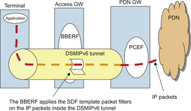
Figure 8.2.3.5.2 BBERF ‘tunnel look-through’ in case DSMIPv6 is used.
8.2.3.6 Events and renewed policy decisions
When the PCRF makes a policy decision, information received from the access network may be used as input. For example, the PCRF may be informed about the current access technology used by the UE, or whether the user is in their home network or is roaming. During the lifetime of a session, the conditions in the access network may however change. For example, the user may move between different access technologies or different geographical areas. There may also be situations where a certain authorized GBR can no longer be maintained over the radio link. In these cases, the PCRF may want to re-evaluate its policy decisions and provide new or updated rules to the PCEF (and BBERF, if applicable). The PCRF should thus be able to keep itself up-to-date about events taking place in the access network. To achieve this, procedures have been defined that allow the PCRF to notify the PCEF/BBERF about which events the PCRF is interested in. In PCC terminology we say that the PCRF subscribes to certain events, and that the PCEF/BBERF sets the corresponding event triggers. When an event occurs, and the corresponding event trigger is set, the PCEF/BBERF will report the event to the PCRF and allow the PCRF to revisit its previous policy decisions.
In the ‘on-path’ model, information about the access network (e.g. information regarding available QoS on radio link, etc.) is available in the PDN GW and the PCEF can thus report on any status change via the Gx reference point. As mentioned above, there is no need for the BBERF in this case. In the ‘off-path’ model, however, the PCRF will need to subscribe to events either in the PCEF or in the BBERF, depending on the nature of the event. With Mobile IP-based protocols, the access-specific bearers terminate in the BBERF instead of the PCEF. This implies that certain information about the access network is only available to the BBERF. Therefore, the BBERF detects such events and reports them over the Gxa/Gxc reference points. Other events, such as events related to multi-access mobility, are only known to the PCEF and thus reported by the PCEF also in the ‘off-path’ model.
In the ‘off-path’ model, the Gxa/Gxc and Gx interfaces will also be used for more generic parameter transfer. Some of the information provided by the BBERF is also needed in the PDN GW/PCEF. For example, the PDN GW may need to know which 3GPP radio technology is used (GERAN, UTRAN or E-UTRAN) to enable proper charging and this information is not necessarily provided via the PMIP-based S5/S8 reference point. It must then be provided by the BBERF to the PCEF (PDN GW), via the PCRF, as illustrated in Figure 8.2.3.6.1.
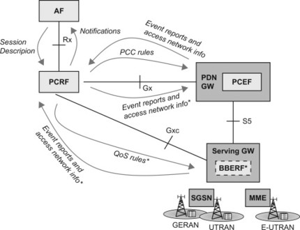
Figure 8.2.3.6.1 High-level information flow. Items marked with * apply to off-path model only. Only 3GPP family of accesses is shown in the figure for simplicity.
Also the AF may be interested in notifications about conditions in the access network, such as what access technology is used or the status on the connection with the UE. Therefore the AF may subscribe to notifications via the Rx reference point. In this case it is the PCRF that reports to the AF. The notifications over Rx are not directly related to renewed policy decisions in the PCRF, but event triggers play a role also here. The reason is that in case the AF subscribes to a notification over Rx, the PCRF will need to subscribe to a corresponding event via Gx or Gxa/Gxc interface.
Figure 8.2.3.6.1 shows a high-level summary of the information flow in a PCC architecture.
8.2.3.7 Functional allocations
Most functions of the PCEF are common to both ‘on-path’ and ‘off-path’ models. For example, service level charging, gate control, QoS enforcement and event reporting are done in the PCEF in both cases. However, as we have also seen above, the bearer-related functions and certain event reporting need to be performed by the BBERF in the ‘off-path’ case. Table 8.2.3.7.1 summarizes the allocation of different functions in the two architecture alternatives.
Table 8.2.3.7.1 Allocation of functions in ‘on-path’ and ‘off-path’ models.
| ‘on-path’ (BBERF is not used) | ‘off-path’ (BBERF is used) | |
| Service level charging (flow based charging) | PCEF | PCEF |
| Service level gating control | PCEF | PCEF |
| Service level UL and DL bit rate enforcement | PCEF | PCEF |
| Bearer binding | PCEF | BBERF |
| Event reporting | PCEF | BBERF and PCEF |
8.2.4 Network vs. terminal-initiated QoS control
As was already indicated in the two use cases above, there are two basic methods for initiating the QoS allocation in the access; either triggered by the UE or triggered by the network. We refer to these as the terminal-initiated and network-initiated QoS control paradigms. Below we look in more detail at a few general aspects of the two paradigms.
Originally, GPRS only supported the UE-initiated QoS control paradigm. To use UE-initiated procedures was very reasonable since there were actually no means to trigger resource reservation procedures from the network until policy control was introduced in 3GPP. However, in 3GPP Rel-7, when PCC was developed, a mechanism became available to trigger QoS resource reservation from the network based on application signalling. To support the network-initiated QoS control paradigm, the network-initiated secondary PDP context activation procedure was introduced in Rel-7 GPRS. For EPS, both network-initiated and terminal-initiated procedures are supported for GERAN/UTRAN and E-UTRAN. CDMA2000 systems specified by 3GPP2, including the eHRPD, support terminal-initiated procedures in general, while network-initiated procedures have been introduced for the eHRPD system.
With the terminal-initiated QoS control paradigm, it is the terminal that initiates the signal to set up a specific QoS towards the network. For the particular case of E-UTRAN, the terminal would send a request for bearer resources to the network. The application in the terminal must know what QoS that it wants, and trigger the access interface part in the terminal (e.g. the E-UTRAN part) over a terminal-internal ‘interface’, or Application Programming Interface (API). This API is typically not standardized and may, for example, differ between terminal vendors and access technologies; the usage of the API is illustrated in step 4 of the second use case in Section 8.2.3.3. This means that in order to specify the QoS information for the access, the client applications need to be aware of the specifics of the QoS model of the access network. With this paradigm, there is no need for a PCRF to push QoS information to the network. A PCRF may however still be used to authorize the QoS resources requested by the terminal, as was illustrated in the second use case above. The terminal-initiated QoS control principles have been illustrated in Figure 8.2.4.1.
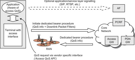
Figure 8.2.4.1 Terminal-initiated QoS control.
Using network-initiated QoS control, it is the network that initiates the signal to set up specific QoS towards the terminal and the radio network. For the particular case of E-UTRAN, it would be the network that initiates the dedicated bearer procedure. The trigger for this signal is received from other network nodes, typically an AF in combination with a PCRF. The signalling is sent over standardized references points such as Rx and Gx. This scenario is described by the first use case in Section 8.2.3.3 and has also been illustrated in Figure 8.2.4.2.
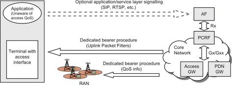
Figure 8.2.4.2 Network-initiated QoS control.
Using the network-initiated paradigm, the client application does not need to worry about the specifics of the QoS model of the access network. The application in the terminal can instead rely on the network to ensure that the access-specific QoS procedures are executed as needed. The application may however have access agnostic knowledge of the QoS that it wants to be provided with and make a request for this QoS via the application layer. For example, the QoS to be applied to the session may be negotiated with the network by means of application-layer signalling such as SIP and Real Time Streaming Protocol (RTSP) combined with the SDP. Note, however, that there is no access specific information in this signalling. This property of network-initiated QoS control is very attractive since it can be used to provide QoS to access agnostic client applications, for example, applications that are downloaded and installed by the user. This is not possible for terminal-initiated QoS control which requires access-specific client applications that need to be programmed towards a vendor-specific QoS API. The possibility to be ‘access QoS agnostic’ also enables QoS to be provided in the ‘split terminal’ case where the client applications reside in a node (e.g. a laptop or set top box) that is physically separated from the terminal. The signalling for a network-initiated QoS control was illustrated already in the first use case in Section 8.2.3.3.
A prerequisite for the network-initiated paradigm, is that the network is able to understand what QoS resources are needed for the service. However, in practice many services (e.g. Mobile-TV, IMS voice) are actually provided by the access network operator; possibly through agreements with third-party service operators, and are thus known to the operator. It is therefore reasonable that the operator also assigns the QoS level for the SDF associated with the service.
Due to the mentioned advantages with network-initiated QoS control paradigm, we consider it to be the most beneficial in cases where the operator controls and has full knowledge of the service. For services not known to the operator there is also a possibility to use the terminal-initiated QoS control paradigm. An example may be that the user accesses a streaming server (not known to the operator) on the Internet and the application in the terminal wants to set up premium QoS for that service. In this case terminal-initiated QoS could be used, assuming that it is allowed by the operator.
8.2.5 PCC and roaming
As already briefly mentioned in Chapter 3, PCC in 3GPP Rel-8 supports roaming for both on-path and off-path scenarios. When a user is roaming in a visited network, we distinguish between two main roaming cases: the ‘Home Routed’ case and the ‘Visited Access’ case. The last alternative is often also called ‘Local Breakout’ (LBO). In the Home Routed case, the user is connected through a PDN GW in the home network and all traffic for that IP connection is routed via the home network. In the Visited Access case, the user is connected via a PDN GW in the visited network and traffic is transported between the UE and the PDN without traversing a PDN GW in the home network. Since the PCEF is located in the PDN GW, this means that the PCEF may be located in the home or visited network. The BBERF (if applicable) is always located in the visited network when the user is roaming.
To support such roaming scenarios, two different architecture alternatives would be possible:
-
One alternative would be that the PCRF in the home network directly controls the PCEF and/or BBERF in the visited network via Gx and/or Gxa/Gxc interface.
-
Another alternative would be to introduce a reference point between the PCRF in the home network and a PCRF in the visited network. The Gx/Gxa/Gxc interface would then go between the visited PCRF and the PCEF/BBERF in the visited network.
One main principle when developing the PCC architecture for these roaming scenarios has been that no policy control entity is allowed to directly control a policy enforcement entity in another operator’s network. The interaction should always go via a policy control entity in the same network as the policy enforcement entity. Therefore it was decided to go for the second alternative above, introducing a new reference point, S9, between two PCRFs, one in the home network and one in the visited network. These two PCRFs are denoted Home PCRF (H-PCRF) and Visited PCRF (V-PCRF) respectively. The two roaming scenarios and the associated PCC architecture are illustrated in Figure 8.2.5.1. It should be noted that in the Visited Access case, the AF may be associated with either the home or the visited network.
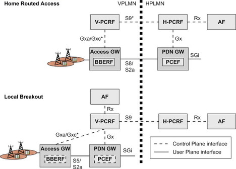
Figure 8.2.5.1 PCC architecture for home routed and visited access (local breakout) roaming cases. Items marked with * are Only applicable to off-path model.
Control of allowed services and the authorization of resources are always handled by the H-PCRF. Since the home operator provides this control in both roaming and non-roaming scenarios a consistent user experience is possible. For the roaming scenarios when S9 is used, the V-PCRF may accept or reject, but not change, policy decisions coming from the home network. This allows the visited operator to control the usage of the resources in its (radio) access network.
In the Home Routed roaming scenario the PCEF is located in, and controlled by, the home operator. The PCEF connects to the H-PCRF via Gx and online charging can be performed via Gy to the OCS in a similar way as for non-roaming scenarios.
If the on-path model is used, that is, the roaming interface for home routed traffic is based on GTP, there is no need for a BBERF or Gxa/Gxc, and consequently no V-PCRF or S9 either. All QoS signalling with the visited network is taking place over S8 using GTP. There is no need to invoke a PCRF in the visited operator’s network. This roaming model is basically the same as that existing for pre-EPS GPRS.
If the off-path model is used, that is, if the roaming interface for home routed traffic is using a Mobile IP-based protocol; the S9 reference point is needed. The BBERF in the visited network is connected via a V-PCRF to the H-PCRF over the S9 reference point. For this case the H-PCRF is responsible for controlling the BBERF in the visited network, via the V-PCRF. Consequently the H-PCRF provides policy decisions (QoS rules) to the BBERF in the visited network, via the V-PCRF.
In the Visited Access case a PDN connection is established via a PDN GW in the visited operator’s network. If GTP is used towards the PDN GW in the visited network, then the PDN GW (PCEF) is connected via a V-PCRF to the H-PCRF via S9. On the other hand, if a Mobile IP-based protocol is used towards the PDN GW in the visited network, then the S9 reference point and also the role of the V-PCRF become more complex. The reason is that both Gx and Gxa/Gxc procedures are handled within the same S9 session. The V-PCRF must be able to split and combine messages between S9 on one side and Gx and Gxa/Gxc on the other side.
In the Visited Access case the V-PCRF and the S9 reference point are used independent on whether the visited network is using the on-path or off-path architecture. It would therefore be desirable that the S9 interface would also be independent of the PCC model. Naturally this is not possible to achieve in the Home Routed case since the S9 only exists when off-path is used. In the Visited Access case however, it is to a large extent possible to ‘hide’ the Gxa/Gxc aspects in the visited network from the S9 interface. This has been one of the goals when designing the S9 protocol. For additional details, see Chapter 10 and 3GPP TS 29.125 [29.125].
For the Visited Access scenario it is possible to use AFs connected via Rx to the V-PCRF. In this situation, Rx signalling is forwarded via the V-PCRF to the H-PCRF using S9.
8.3 Charging
As operators invest in new infrastructure and persuade end-users to enjoy the benefits of the newly deployed networks, the revenue generating options become a key factor for the business cycle. How the end-users/subscribers are actually charged and how billing information is packaged towards them is very much according to individual operator’s business model and competitive environment they are operating in. From the EPS point of view, the system needs to enable collection of enough information related to different aspects of the usage for individual user so the operator has the flexibility to determine his own variant of billing as well as packaging towards the end-users. It has become increasingly important in today’s competitive business environment for the operators to be able to provide lucrative and competitive option packages towards their potential customers to lure businesses away from other operators. The process of collecting information related to charging can provide tools and means for the operators to make this possible.
For EPS, the existing charging models as well as mechanism apply except for the circuit-switched domain charging aspects of course.
The 3GPP charging infrastructure principles and mechanism did not change due to EPS, but rather EPS entities have been included within this infrastructure. Figure 8.3.1 shows the overall high-level charging system reference model.
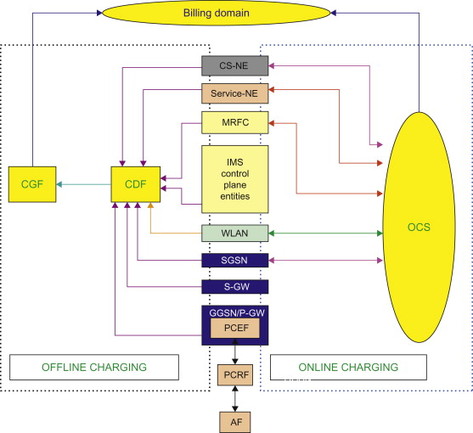
Figure 8.3.1 Overall logical high-level reference model for collection of charging information.
The two main charging mechanisms provided by the model are Offline and Online charging, though the terms Online and Offline are not necessarily related to how the end-users are billed at all. These two mechanisms are the means of how the charging-related data are collected and transported to the billing system for further processing as per individual customer’s billing options and for settling accounting relations between operators and between operators and subscribers. Offline charging facilitates collection of charging-related data concurrently as the resources are being used in a specific network’s various elements provisioned to support such collection of information on an individual basis and then may be sent towards the billing system/domain according to the operator’s configuration. Whereas Online charging requires the network to actually get authorization of network resource usage before such usage can occur and the OCS (Online Charging System) is the authorization entity which either grants or rejects the request made by the appropriate network element. In order to do this, the network needs to assemble the relevant charging- and resource usage-related information (known as charging event) and send it to the OCS in real-time, thus allowing OCS to make the appropriate level of authorization which may be limited in its scope such as the volume of data or time of usage, etc. Depending on the level of authorization, the network may need to get a re-authorization performed for any additional resource usage. Note that information collected by the charging system can be used in various manners, such as it may provide statistical measure of network resource usage at certain time of day, usage behaviour, application usage, etc.
In case of Offline charging, various network elements can have a distributed collection role, which would allow for more detailed information availability. Alternatively they may have a centralized role, with a limited collection of events capability as per the entity’s role within the network. This role is specified by the Charging Trigger function (CTF) that causes the entities to collect charging events, for example, appropriate charging-related data, and provides them to the Charging Data Function (CDF).
The CDF sends these data towards Charging Gateway Function, which is responsible for sending the data to the billing system. The heart of the Offline system is the CTF which keeps account of usage information regarding the services being delivered to the end-user based on either:
-
Signalling information for sessions and service events by the users of the network or
-
The handling of user traffic for these events and sessions. The Off line charging system can be illustrated in a simplified manner as shown in Figure 8.3.2.
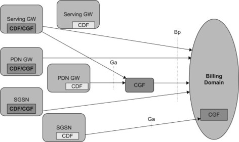
Figure 8.3.2 Off line Charging entities.
The information must be made available in real-time with data that uniquely associates and correlates the user’s consumption of network resources and/or services.
Note that even though it is not required for the various types of information to be sent in a synchronous manner, the overall charging event must be able to receive and process all relevant data for a specific service/session in real-time in order to provide accurate, billable data towards end-users. So all offline processing of Charging Data Records (CDR) towards the end-user’s billing is performed after the usage of the network resources is complete. The billing domain is responsible for generation and handling of the settlement/billing process offline.
In case of Online charging, the CTF and OCS and several other network entities form the charging function. The OCS contains functions like Online Charging Function (OCF), Rating Function (RF) and Account Balance Management Function (ABMF) in order to handle the online charging process. The OCF is the entity that connects to the network elements responsible for providing the charging data, that is, it supports the CTF function. Even though the CTF performs very similar functions for both the Offline and Online charging mechanisms, online charging requires additional handling for authorization prior to the resource usage and thus also requires additional functions from the CTF which are crucial for the real-time Online process. Some of these functions are:
-
The charging events are sent to the OCF in order to retrieve authorization for the chargeable event/network resource usage requested by the user.
-
The CTF must be able to delay the actual resource usage until permission has been granted by the OCS.
-
The CTF must be able to track the availability of resource usage permission (‘quota supervision’) during the network resource usage.
-
The CTF must be able to enforce termination of the end-user’s network resource usage when permission by the OCS is not granted or expires.
The OCF supports two methods of charging:
-
Session-Based Charging Function providing online charging for the network/user’s sessions, examples of such services could be the PS resource usages for IMS sessions.
-
Event-Based Charging Function (i.e. content charging) provides online charging in support of application server or service, such as SIP AS or MMS.
The Rating Function is responsible for providing the OCF with the actual value of the network resource usage/service usage, which may be either monetary or non-monetary information. This is determined by information provided by the OCF and CTF; the actual rating or determining the value of the usage is very much operator specific and can be quite wide ranging, some basic examples of such rating could be as follows:
-
Rating of data volume (e.g. based on charging initiated by an access network entity, that is, on the bearer level).
-
Rating of session/connection time (e.g. based on charging initiated by an IMS level application).
-
Rating of service events on the service level (e.g. based on charging of web content or MMS).
The ABMF is responsible for the subscriber’s account balance within OCS.
In the case of Online charging, the network resource usage must be authorized and thus a subscriber must have a pre-paid account in the OCS in order for the Online pre-network resource usage authorization to be performed. The two methods used to achieve this are known as Direct Debiting and Unit Reservation. As their names imply, in case of Direct Debiting, the user is immediately debited the amount of resource usage needed for that specific service/session, where as in case of Unit Reservation a predetermined unit is reserved for the usage and the user is then allowed to use that amount, or less, for that service/session. When resource usage has been completed (i.e. session terminated, or the service is completed, etc.), the actual amount of resource usage (i.e. the used units) must be returned by the network entity responsible for monitoring the usage, to the OCS so that over-reserved amounts can be re-credited to the subscriber account, ensuring that the correct amount gets debited.
Note that PCC makes it possible to have quite detailed charging mechanisms and allows for the possibility of operators having granular control over the subscriber’s usage of the network resources. PCC also allows operators to offer various flexible charging and policy schemes towards their subscribers. More details can be found in Section 8.2 on policy control and charging.
For Online charging, the PCEF function as specified in the PCC section interacts with the OCS as specified above and provides the Online charging functions in the PS Domain. Note that the GGSN in GPRS provides the PCEF functions and related support for PCC for Online charging. It also provides the necessary configuration options as specified here for PDN GW in case of Offline charging; GGSN aspects are not described within the context of EPS. Key functions related to charging data collection triggers in the EPS can be described on a high level as follows; it should however be noted that much of the standardization for charging is still underway at the time of writing. We have therefore provided a high-level overview and indicated which parts are still under consideration. Readers are therefore advised to check the relevant charging specifications for more details.
Mobility management-related events relevant for charging, for example, Inter-RAT handover, user’s activity/inactivity during established sessions and roaming/non-roaming status, etc., are collected at the SGSN. The authors of this book believe that similar functions are also needed in the MME. However, at the time of writing this book, the standardization process in 3GPP had not been fully completed and the functions mentioned are currently not provided by the MME.
IP-CAN bearers and related functions may be collected at the SGSN/MME (again, this is still under consideration in 3GPP) and Serving GW/PDN GW. Individual service data flows within an IP-CAN bearer according to PCC may be collected at PDN GW but only for the GTP protocol variant. At the time of writing, for the case of PMIP, the data is collected on a per-PDN level but is still undergoing work in the standards body within 3GPP.
At the time of writing, the MBMS and Location Services EPS have remained work in progress and thus unspecified, though charging for these functions is supported in GPRS.
While the SGSN/MME and Serving GW charging data collection is more related to the radio access type used, the PDN GW collects for external network-related data relevant to a subscriber. A subscriber’s subscription-related data can also be relevant for charging, an example of such data would be the APN used, more on APN can be found on session management subsection in Chapter 6. A unique charging Identity is assigned; uplink and downlink data volume, date and time are collected for individual subscriber for the purpose of charging.
One example of items that may be contained in a CDR record generated by a PDN GW, as depicted in 3GPP TS 32.251, is illustrated in the table below:
Table 8.3.1 Example of items that may be contained in CDRs generated by the PDN GW.
| Field | Description |
| Served IMSI | IMSI of the served party. |
| Served MN NAI | Mobile Node Identifer in NAI format (based on IMSI), if available. |
| P-GW Address used | The control plane IP address of the PDN GW used. |
| Charging ID | IP CAN bearer identifer used to identify this IP CAN bearer in different records created by PCNs. |
| PDN Connection Id | This feld holds the PDN connection identifer to identify different records belonging to same PDN connection. |
| Serving node Address | List of SGSN/Serving GW control plane IP addresses used during this record. |
| Serving node Type | List of serving node types in control plane. The serving node types listed here map to the serving node addresses listed in the feld “Serving node Address” in sequence. |
| PGW PLMN Identifer | PLMN identifer (Mobile Country Code and Mobile Network Code) of the PDN GW. |
| Access Point Name Network Identifer | The logical name of the connected access point to the external packet data network (network identifer part of APN). |
| PDP/PDN Type | PDP type or PDN type (i.e. IPv4, IPv6 or IPv4v6). |
| Served PDP/PDN Address | IP address allocated for the PDP context / PDN connection, i.e. IPv4 or IPv6. |
| Dynamic Address Flag | Indicates whether served IP address is dynamic, which is allocated initial attach and UE requested PDN connectivity. This feld is missing if the IP address is static. |
| List of Service Data | Consists of a set of containers, which are added when specifc trigger conditions are met. Each container identifes the confgured counts (volume separated for uplink and downlink, elapsed time or number of events) per rating group or combination of the rating group. |
| Record Opening Time | Time stamp when IP CAN bearer is activated in this PDN GW or record opening time on subsequent partial records. |
| MS Time Zone | This feld contains the MS Time Zone the MS is currently located, if available. |
| Duration | Duration of this record in the PDN GW. |
| Cause for Record Closing | The reason for the release of record from this PDN GW. |
| Record Sequence Number | Partial record sequence number, only present in case of partial records. |
| Record Extensions | A set of network operator/manufacturer specifc extensions to the record. Conditioned upon the existence of an extension. |
| Local RecordSequence Number | Consecutive record number created by this node. The number is allocated sequentially including all CDR types. |
| Served MSISDN | The primary MSISDN of the subscriber. |
| User Location Information | This feld contains the User Location Information of the UE |
| Serving node PLMN Identifer | Serving node PLMN Identifer (Mobile Country Code and Mobile Network Code) used during this record. |
| RAT Type | This feld indicates the Radio Access Technology (RAT) type currently used by the Mobile Station, when available. |
| Start Time | This feld holds the time when User IP session starts, available in the CDR for the frst bearer in an IP session. |
| Stop Time | This feld holds the time when User IP session is terminated, available in the CDR for the last bearer in an IP session. |
Explicit identifiers are used in each of the domains: CS, PS, IMS and Applications that are involved in a specific session; this is because charging data is collected in several network entities and also is needed in order to settle inter-operator resource usage when a user is roaming. In EPS, the Charging Identity for EPC and the PDN GW Identity makes up this identification.
Various levels of correlation are supported in order to achieve a complete charging information profile for the individual usage for each subscriber. Intra-level correlation aggregates the charging events belonging to the same charging session, for example, over a time period, and implies the generation of interim charging records. When an end-user has accessed a service during the same session from different radio accesses or while roaming, the network entities involved in charging perform correlation of the data. Inter-level correlation combines charging events generated by the different CTFs in different 3GPP domains and inter-network correlation for the IMS requires generation and transmission of specific identifiers across operators’ networks. An example of the different level of correlation could be, an end-user in E-UTRAN access connected via EPC using MMTEL service towards an end-user connected to another operator in another network. All three types of correlation would then be generated (if supported and required) by the different operators and the specific domains.
How can all these be configured for a subscriber? Subscriber charging provides the means to configure the end-user’s charging information into the network. Charging data collected by the different PLMNs involved (e.g. HPLMN, Interrogating PLMN and VPLMN) and may be used by the subscriber’s home operator, dependant upon the deployment and user’s roaming status, to determine the network usage and the services, either basic or supplemental. There may also be the possibility to use external Service Providers for billing.
For those subscribers handled by Service Providers, the billing information is utilized for both wholesale (Network Operator to Service Provider) and retail (Service Provider to subscriber) billing. In such cases, the charging data collected from the network entities may also be sent to the Service Provider for further processing after the Home PLMN operator has processed the information as may be desired. Figure 8.3.3 illustrates the different business relationships from the perspective of charging and billing – for the purposes of this book, the circuit-switched aspects are excluded.
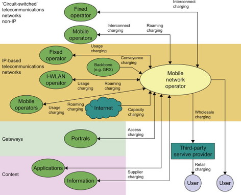
Figure 8.3.3 3GPP view on charging relationship [TS 22.115].
The entities and their roles can be described as follows:
Users: Retail users that are charged by their Mobile Network Operator or third-party service provider. Normally users have subscriptions or similar relationship with either or both parties.
Third-Party Service Providers: charged wholesale by the Mobile Network Operator. Responsible for providing users the billing and other charging-related customer care type services towards the users for services rendered.
Other telecommunications operators: interconnect charging between Mobile Network Operator and non-IP ‘circuit-switched’ Network Operators for call traffic carried; usage charging between Mobile Network Operator and IP-based Network Operators for session traffic carried. For the purposes of the current section, this group is of no interest.
Other mobile operators: roaming charging between these entities, this may require different mechanisms for IP-based types from the traditional ‘circuit-switched’ types. Also, where mobile operators need to pass traffic to one another, there will be interconnect charging for non-IP ‘circuit switched’ types; usage charging for IP-based types.
I-WLAN operators: where I-WLAN operators need to pass traffic to mobile operators or mobile operators to I-WLAN operators, there may be roaming and usage charging.
IP backbone carriers: conveyance charging Mobile Network Operators for traffic carried.
Third-Party content and application suppliers: supplier charging between Mobile Network Operators and Value-Added Service Providers for information exchanged.
Third-Party Portals: access charging between Mobile Network Operators and this entity.
Internet: charge for capacity of connection between Mobile Network Operator and Internet. An Operator pays a provider for a connection based on capacity, for example, annual charge for a 2Mbit/s ‘pipe’.
Some of these roles can be easily derived when evaluating the deployment and roaming scenarios for EPS.
EPS is an all-IP based network where Diameter is used for all charging data collection related functions within the EPS. Though support for CAP, GTP’ as well as TAP remain due to existing widely deployed and used billing systems by the operators as well as for interworking and backwards compatibility with 2G/3G networks. The interfaces towards the billing system rely heavily on the operators’ business model and billing principles and may involve third-party service providers which affect the end-users directly and may be visible towards the end-users if changed drastically and these are not easily feasible.
As charging data can not only convey operator’s business aspects, but it may also reveal sensitive information regarding individual subscriber, transfer of such information towards external entities outside of an operator’s secure domain must also be done in a secure manner so that information may not be disclosed to unauthorized personnel or entities. Integrity of charging information must be maintained; privacy and secrecy is integral and must be provided by the serving operator and validation of the content and receipt of charging information by the serving Network Operator must be possible. Note that by serving Network Operator, we mean both home and visited as well as any intermediary Network Operators/third-party providers involved in the transaction and handling of the charging/billing.