
Fuels and Combustion
Fuels are energy sources, classified as fossil fuel, nuclear fuel, and rocket fuel. Fossil fuels are hydrocarbons. There are three basic types of hydrocarbons, i.e., solid, liquid, and natural gas. The largest source of fossil-fuel energy is coal. In addition to fossil fuel, energy is available from renewable sources. Fossil fuels comprise complex compounds of five elements: carbon, hydrogen, oxygen, sulfur, and nitrogen along with mineral matter and moisture. Coal generates ~41% of the world’s electricity and provides 30% of primary energy needs. Petroleum comprises a mixture of innumerable hydrocarbons in liquid form or natural gas. Combustion is a process where oxygen combines rapidly with fuels to release substantial amount of heat. Proper combustion of a fuel is assured by temperature, turbulence, and time. Combustion calculations facilitate the design and performance determination of boilers and the associated components. The fuel burner provides proper mixing of fuel and air to ensure complete combustion.
Keywords
fuel; air; combustion; heating value; characteristics; analysis; burner; flame; furnace
3.1 Introduction
Any matter that is a source of heat is called fuel [1]. Fuel releases its energy either through a chemical reaction, such as during combustion, or via nuclear fission or fusion. An important property of a useful fuel is that its energy can be stored and released only when needed, and that the release is controlled in such a way that the energy can be harnessed to produce the desired work. Fuels are broadly classified as fossil or organic or chemical fuel, nuclear fuel, and rocket fuel.
Fossil fuels are hydrocarbons, primarily coal and petroleum (liquid petroleum or natural gas), formed from the fossilized remains of dead plants and animals by exposure to heat and pressure in the earth’s crust over hundreds of millions of years. Fossil fuels generate substantial quantities of heat per unit of mass or volume by reacting with an oxidant in a combustion process. In most practical applications including combustion in a steam generator, air is used as the oxidant, although in certain processes oxygen, oxygen-enriched air and other chemicals are used as the oxidant.
Energy generation by a nuclear fuel takes place either by the process of nuclear fission of heavy fissile elements in a nuclear reactor resulting in chain reactions or by the process of nuclear fusion, in which simple atomic nuclei are fused together to form complex nuclei, as in case of fusion of hydrogen isotopes to form helium. The process of nuclear fusion is also known as a thermonuclear reaction, which is difficult to control even today. As a result, the main source of nuclear energy presently available is mainly from nuclear fission. The most common fissile radioactive heavy metals are naturally occurring isotope of uranium, U235, artificial isotope of uranium, U233, and artificial element plutonium, P239. In a nuclear reactor plutonium, P239, is produced from naturally occurring isotope of uranium, U238, and U233 is produced from the naturally occurring element thorium, Th232. Nuclear fission of 1 kg of U235 generates about 85*106 MJ of heat, which is equivalent to the heat generated by combustion of about 5*106 kg of coal with a high heating value (HHV) of 17 MJ/kg. In nuclear reactions, the product is either isotopes of the reactants or other nuclei.
Unlike fossil fuel, rocket fuel does not depend on its surroundings for the oxidant. The oxidant is carried by the rocket itself. The propellant is the chemical mixture burned to produce thrust in rockets and consists of a fuel and an oxidizer. Propellants are classified according to their state – liquid, solid, or hybrid. In a liquid-propellant rocket, the fuel and oxidizer are stored in separate tanks, and are fed to a combustion chamber where they are combined and burned to produce thrust. Liquid propellants used in rocketry can be highly refined kerosene, liquid hydrogen (LH2), liquid methane, etc. Solid propellant motors are the simplest of all rocket designs. Unlike liquid propellant engines, solid propellant motors cannot be shut down. Once ignited, they will burn until all the propellant is exhausted. The fuel is generally aluminum and the propellant is ammonium perchlorate. In hybrid propellant engines fuel is generally solid and the oxidizer is liquid.
Besides availability of energy from various form of fuels, energy is also available from sun, wind, tides, geothermal, biomass, etc., which are broadly called renewable sources of energy. Commercial use of such energy at present, however, is not large scale in many countries.
3.2 Sources of Chemical Energy
In steam power plants, fossil fuels that produce large quantities of heat economically have been used for combustion. These fuels are abundantly available in nature and their extraction process is reasonably simple. Most widely used fossil fuels for the production of steam in relation to power are available in all the states of matter, e.g., gaseous–natural gas, blast furnace gas, coke-oven gas, liquefied petroleum gas or (LPG), etc., liquid – high-speed diesel (HSD), light diesel oil (LDO), heavy fuel oil (HFO), furnace oil (FO), low sulfur heavy stock (LSHS), naphtha, liquefied natural gas (LNG), etc., and solid–bituminous coal, anthracite, lignite, peat, oil shale, biomass, etc.
Fossil fuels consist of a large number of complex compounds of five elements: carbon (C), hydrogen (H), oxygen (O), sulfur (S), and nitrogen (N). Besides these elements, all fuels contain mineral matter (A) and moisture (M) to some extent. However, there are just three combustible elements of significance in a fuel, e.g., carbon, hydrogen, and sulfur, of which carbon is the principal combustible element with a HHV of 32.780 MJ/kg. Hydrogen has a very high HHV of 141.953 MJ/kg, but its content in solid fuel is quite low, about 2–4%. The HHV of sulfur is only 9.257 MJ/kg, hence as a source of heat its presence is insignificant, although it is more so since its presence in coal is small in quantity. Major concern regarding sulfur is that it promotes corrosion and creates atmospheric pollution problems.
Contrary to solid and liquid fuels, gaseous fuels are mixtures of combustible and non-combustible gases. NFPA 85 defines natural gas as “A gaseous fuel occurring in nature and consisting mostly of organic compounds, normally methane (CH4), ethane (C2H6), propane (C3H8), and butane (C4H10) [2]. The calorific value of natural gas varies between 26.1 and 55.9 MJ/m3, the majority averaging 37.3 MJ/m3.” Natural gas on average contains 80–90% methane, 6–9% ethane, and 2–5% propane. Non-combustible gases present in minor quantities in natural gases are nitrogen (0.5–2.0%) and carbon dioxide (0.1–1.0%).
LPG, as per NFPA 85, is “A material composed predominantly of the following hydrocarbons or mixtures of them: propane, propylene, n-butane, isobutene, and butylenes” [2]. The mixture is liquefied at room temperature at very high pressure. An average mixture of LPG is comprised of about 80% butane and about 20% propane.
In addition to these fuels, other fuels have also been used as sources of chemical energy for combustion. Some of these fuels are coke, peat, bagasse, tars and char, wood, rice husk, producer gas (product received by burning coal or coke in air deficient environment in presence of controlled amount of moisture), water gas (produced by passing steam through a bed of hot coke; the product contains mainly hydrogen and carbon monoxide), etc.
3.2.1 Heating value
The heating value of a fuel is the amount of heat recovered when the products of complete combustion of a unit quantity of fuel are cooled to the initial temperature (298 K) of the air and fuel. As the heating value of fuel increases, the heat content delivered to the burners increases. The heat of combustion of a fuel is also called its potential heat.
When a fuel is burned in oxygen saturated with water vapor, the quantity of heat released is known as the high heating value (HHV), or gross calorific value (GCV), of fuel. When the latent heat of water vapor contained in the combustion products is subtracted from the HHV we get the low heating value (LHV) or net calorific value (NCV) of fuel. In a laboratory, the HHVs of solid and liquid fuels are determined at constant volume and those of gaseous fuels are determined at constant pressure. Combustion in a furnace, however, takes place at constant pressure.
For bituminous coal and anthracite, the HHV can be calculated approximately by Dulong’s formula, as follows, which will be within 2–3% of the value determined by the calorimeter.
(3.1)
Once the value of HHVCOAL is known, either from laboratory determination or from Dulong’s formula, the LHVCOAL is then calculated as follows:
(3.2)
where C, H, O, S, and M correspond to carbon, hydrogen, oxygen, sulfur, and moisture content of coal, respectively, expressed in parts by weight of each constituent, and heat of condensation of water vapor at 298 K is 2.44 MJ/kg.
3.3 Availability of Fuels
Fossil solid fuels are available in almost all countries but are distributed unevenly. The majority of countries is not rich in coal production. There are around 70 countries that contain recoverable coal reserves. The largest producer of hard coal is the People’s Republic of China (about 3561*109 kg was produced in the year 2013) [3], followed by the United States, India, Indonesia, Australia, Russia, and South Africa. Germany, Poland, and Kazakhstan also contribute to global coal production to some extent.
The largest producer of lignite (brown coal) is Germany (about 183*109 kg produced in the year 2013). Russia, the United States, Poland, Turkey, Australia, Greece, and India also produce lignite. Coal is the major fuel used to generate over 40% of the world’s electricity demand and provides 30% of global primary energy needs. Coal is also used in the production of 70% of the world’s steel [3]. Almost all (93% or more) electricity-generating stations in Mongolia and South Africa are coal-fired [3]. Other countries that depend heavily on coal for electricity generation are Poland, the People’s Republic of China, India, Australia, Israel, Indonesia, Germany, the United States, the United Kingdom, and Japan. Globally about 7823*109 kg of hard coal and brown coal were produced in the year 2013. At the current production level, proven coal reserves are estimated to last 134.5 years as estimated by the German Federal Institute for Geosciences and Natural Resources (BGR), and the World Energy Council (WEC) reports that the coal reserves left are equivalent to 113 years of coal output [3].
Petroleum is a term that includes a wide variety of liquid hydrocarbons. The most familiar types of petroleum are tar, oil, and natural gas. Petroleum is found in porous rock formations in the upper strata of some areas of the earth’s crust. There is also petroleum in oil sands (tar sands). Petroleum deposits can be found in almost all parts of the world, but commercial exploration stretches from Indonesia throughout Mayanmar, India, the Middle East, Central Europe, Africa, to North and South America. Over 50% of the world’s oil reserves are in the Middle East. As of 2012, the known reserves of petroleum are typically estimated to be around 210.5*109 m3.
Oil accounts for a large percentage of the world’s energy consumption, ranging from a low of 32% for Europe and Asia, up to a high of 53% for the Middle East. Other geographic region consumption patterns are as follows: South and Central America (44%), Africa (41%), and North America (40%).
More than 110 countries produce petroleum globally. According to Businessinsider, the largest supplier of petroleum oil in the year 2012 was Saudi Arabia, followed by the United States, Russia, Iran, People’s Republic of China, Canada, United Arab Emirates, Brazil, Kuwait, Iraq, Venezuela, Nigeria, Qatar, Kazakhstan, and Libya [4]. Other countries that produce a substantial amount of petroleum are Angola and Algeria.
Crude oil is also found in semi-solid form mixed with sand as in the Athabasca oil sands in Canada, where it is usually referred to as crude bitumen. Venezuela also has large amounts of oil in the Orinoco oil sands. Canada and Venezuela contain an estimated 570*109 m3 of bitumen and extra-heavy oil.
Oil shales are found in many countries, but the United States has the world’s largest deposits. Oil shales can be converted into crude oil using heat and pressure in a process called destructive distillation.
The world at large consumes 4.8*109 m3 of oil per year, and the top oil consumers largely consist of developed nations. In fact, 21% of global petroleum consumption is from the United States. Other countries that are large consumers of petroleum are the European Union, People’s Republic of China, Japan, Russia, Germany, and India. (Note: Algeria, Angola, Ecuador, Iran, Iraq, Kuwait, Libya, Nigeria, Qatar, Saudi Arabia, United Arab Emirates, and Venezuela are jointly known as OPEC: Organization of Petroleum Exporting Countries.)
Natural gas is a major source of electricity generation through the use of gas turbines and steam turbines in combined cycle modes. Natural gas burns cleaner than other fossil fuels, such as oil and coal, and produces less carbon dioxide per unit energy released. For an equivalent amount of heat, burning natural gas produces about 30% less carbon dioxide than burning petroleum and about 45% less than burning coal.
Natural gas is commercially produced in oil and natural gas fields. Gas produced from oil wells is called casinghead gas or associated gas. Over 66% of gas reserves are concentrated in the Middle East and Russia. As of 2014, the total proven reserves of natural gas in the world as reported by the International Energy Statistics are more than 197*1012 m3 [5]. The world’s largest gas field by far is the offshore South Pars/North Dome gas-condensate field, shared by Iran and Qatar, estimated to have 58×1012 m3 of natural gas in place. The second largest natural gas field is in Russia.
According to the International Energy Agency global production of natural gas in the year 2013 was about 3.48*1012 m3. More than 90 countries produce natural gas. The United States and Russia together is the largest producer, with around 1.35*1012 m3 per annum. Other main contributors are European Union, Iran, Canada, Qatar, Norway, People’s Republic of China, Saudi Arabia, Algeria, The Netherlands, Indonesia, Malaysia, Uzbekistan, Egypt, Turkmenistan, Mexico, United Arab Emirates, Bolivia, Australia, UK, Trinidad and Tobago, and India.
3.4 Characteristics of Coal
Coal is not another form of carbon. It is a fossil fuel or an organic sedimentary rock, formed by the result of temperature and pressure on plant debris; it is far more plentiful than oil or gas. Coal is comprised of a complex mixture of organic chemical substances containing carbon, hydrogen, oxygen, together with small amounts of nitrogen, sulfur, and trace elements such as mercury, selenium, arsenic, fluorine, etc. It also contains various amounts of moisture and minerals.
The different grades of coal include peat, lignite, sub-bituminous, bituminous, semi-anthracite, and anthracite. From a geological perspective anthracite is the oldest form of coal and lignite is the youngest. In the lower ranked group (peat and lignite) coal is low in carbon and high in oxygen. At the upper end, the reverse is true. The amount of hydrogen remains reasonably constant. All ranks of coal oxidize in a normal storage environment.
Peat is the earliest formation of coal from decomposition of organic matter. With increasing depth and increasing temperature this peat changes into lignite. These low rank coals gradually become mature with further increase in temperature and more time.
Mature forms of coal – such as “bituminous” (soft) and “anthracite” (hard) – contain more carbon and less moisture, while, the most immature forms of coal –“peat” and “lignite”– contain the high moisture and lowest carbon.
Anthracite is a hard coal comprised of mainly carbon with little volatile matter. Its moisture content is negligibly small. On the other side of the scale is lignite, which is a very soft coal whose constituents are mainly moisture and volatile matter with very little presence of fixed carbon.
Because of the wide variation in constituents of different forms of coal it is important to know the various characteristics of coal, as discussed in the following, since they affect the burning of coal in a power plant [1]. It is also important to remember that burning an unsuitable coal can reduce the efficiency of a power plant with consequent increase in pollutant emissions.
Caking, coking
An essential property of coal that is important for the production of coke is caking. When caking coals are heated they soften, swell, become plastic, then form lightweight, porous coke particles. These coals are also called agglomerating coals (free swelling index of 1 or greater). They can easily float out of the furnace before they are burned, unless pulverization is sufficiently fine. [NOTE: The ‘free swelling index’ is determined by heating 1 gm of coal sample for a specified time and temperature. The shape of the button formed by the sample coal is then compared to a set of standard buttons. Larger formed button indicates higher swelling index. Oxidized coal tends to have lower swelling index. This index can be used to show caking properties of coal.] [6].
Coal that shows little or no fusing action is called free-burning coal. Free-burning coals do not have the same swelling characteristic (free swelling index of 0.5 or less) and, hence, do not require the same degree of pulverization. Sub-bituminous coals and lignite are classified as free-burning coals. Both caking and free-burning coals can be burned without difficulty in pulverized coal-fired boilers.
When heated at uniformly increasing temperature in an air-less furnace or oven or in an atmosphere very deficient in oxygen, the volatile matter of coal is driven off, leaving behind a residue of fixed carbon and ash. During heating in the range of 620–670 K coal softens and the residue fuses into a solid mass. This is called coke, which is suitable for metallurgical processes.
Caking and coking coals generally have lower oxygen content than free-burning and non-coking coals. All coking coals are caking, but not all caking coals are suitable as coke.
Reactivity of coal
The reactivity or rate of combustion of coal is defined as the rate at which coal combines with oxygen at temperatures above the ignition point. During the progress of heating, a portion of the inherent oxygen of coal also becomes available to the oxidation process. As the oxygen level increases, the fuel reactivity increases. Reactivity is influenced by the particle size as well as by the surface area to mass ratio of the particle.
Ash fusibility or ash-fusion temperature
Ash fusibility is the means of measuring the performance of coals related to slagging and deposit build-up. In general, high fusion temperatures result in low slagging potential in dry bottom furnaces, while low fusion temperatures are considered mandatory for wet-bottom (slag tap) furnaces.
When coal ash is heated, it becomes soft and sticky, as the temperature continues to raise it becomes fluid. Ash-fusibility temperature is measured by heating cones of ash in a furnace arranged to produce either oxidizing or reducing atmosphere. The temperature at which the tip of the cone starts to deform is known as the initial-deformation temperature (IDT). The temperature at which the cone fuses down into a round lump, in which the height is equal to the width at the base, is called the softening temperature (ST). The temperature at which the cone has fused down to a hemispherical lump, where the height of the cone equals one half the width of the base, is known as the hemispherical temperature. When the melted cone spreads out in a flat layer, the temperature is called the fluid temperature.
The softening temperature serves as the single best indicator of clinkering and slagging tendencies under given fuel-bed and furnace conditions. If ash arrives at a heat-absorbing surface at its softening temperature, the resulting deposit is likely to be porous in structure, and may either fall off metal surfaces by its own weight or be removed by soot blowing. If such a deposit builds up in a high-temperature zone, its surface can reach its melting point and then run down the wall surfaces.
The temperature differential between initial deformation and fluid temperatures, if small, indicates that the wall slag will be thin, runny, adhesive, and sticky. This type of slag is extremely difficult to control by soot blowing. As the differential temperature increases, the resulting slag deposit will build up to thicker proportions, which is less adhesive and therefore responds better to removal by soot blowing.
Sulfur
Sulfur in coal exists in three forms: organic, pyritic, and sulfate. Sulfur that is an inherent constituent of coal is organic sulfur, which is considered as a non-removable impurity. Pyritic sulfur occurs primarily as pyrite or mercasite. Sulfate sulfur usually exists as calcium sulfate or iron sulfate.
When coal is burned, sulfur oxides form and emit through the stack. However, the quantity of sulfur oxides emission to atmosphere should comply with local air pollution control regulations.
In addition to its air-polluting properties, sulfur also plays a role in promoting corrosion of air heaters, economizers, and stacks. Sulfur oxides, when combined with moisture in combustion air form acids that may be deposited when the combustion gas is cooled below its dew-point temperature. Sulfur also contributes to clinkering and slagging, and to spontaneous combustion of stored coal.
3.4.1 Analysis of coal
The two different methods of analyzing coal are known as ultimate and proximate. Ultimate analysis determines the proportion of the main chemical elements contained in the coal, i.e., carbon, hydrogen, nitrogen, sulfur, and carbonate contents. The oxygen may be determined chemically but usually is estimated by difference. Thus, the results of ultimate analysis are important since they facilitate combustion calculations. This analysis provides information regarding the primary combustible and non-combustible components that are used to compute combustion air requirements, flue-gas volumes, and the losses associated with the combustion of hydrogen whose latent heat of evaporation is lost with the gas. The results of ultimate analysis are given in various categories, e.g., on a “as received,” “air dried,” “dry,” “dry ash-free,” or “dry mineral matter free” basis. Conversion from one analysis report to another is presented in Table 3.1.
Table 3.1
Conversion of ultimate analysis report of coal from one category to another category
| Given | Required | ||||
| As received (ar) | Air dried (ad) | Dry (db) | Dry ash-free (daf) | Dry mineral matter free (dmmf) | |
| As Received (ar) | – | (100 – Mad)/(100 – Mar) | 100/(100 – Mar) | 100/(100 – (Mar+Aar)) | 100/(100 – (Mar+MMar)) |
| Air Dried (ad) | (100 – Mar)/(100 – Mad) | – | 100/(100 – Mad) | 100/(100 – (Mad+Aad)) | 100/(100 – (Mad+MMad)) |
| Dry (db) | (100 – Mar)/100 | (100 – Mad)/100 | – | 100/(100 – Aad) | 100/(100 – MMdb) |
| Dry Ash-Free (daf) | (100 – (Mar+Aar))/100 | (100 – (Mad+Aad))/100 | (100 – Adb)/100 | – | (100 – Adb)/(100 – MMdb) |
| Dry Mineral Matter Free (dmmf) | (100 – (Mar+MMar))/100 | (100 – (Mad+MMad))/100 | (100 – MMdb)/100 | (100 – MMdb)/(100 – Adb) | – |

M=Moisture Content, MM=Mineral Matter Content, A=Ash Content.
The results of proximate analysis provide information regarding moisture, ash, volatile matter, and by difference, the fixed carbon content of coal. The higher the value of volatile matter the easier the ignition of fuel. On the other hand, the fixed carbon is the main heat generator during the burning of coal. The major contributor to the heating value of coal is fixed carbon together with the amount of volatile matter content of coal.
Proximate analysis of coal in combination with its calorific value facilitates the design of the furnace including burner locations along with determining the quantum of coal required for generating a quantity of steam.
Moisture
All coal contains some natural moisture, since all coals are mined wet. This natural moisture is called inherent moisture and it lies in the pores of the coal and remains within the coal after it is air-dried. Surface moisture, on the other hand, depends on conditions in the mine and the weather during transit. The surface moisture may be removed from coal by heating it to 373–378 K.
Moisture is generally determined quantitatively in two steps: by air-drying and oven-drying. The air-dried component of total moisture is required in the design and selection of coal-handling and coal-preparation equipment. High moisture content may cause serious difficulties in the fuel combustion process. It reduces the heating value of fuel, increases fuel consumption, and the volume of products of combustion. It also results in higher heat losses with flue gases and raises power consumption of induced draft fans. Surface moisture adversely affects pulverizer performance. In the event coal dust is over-dried, it is liable to self-ignite in places where it is stored or accumulates and may become explosive when mixed with air.
Ash
The ash content of coal is the incombustible mineral matter residue that is left behind after coal burns completely. Ash is chiefly comprised of SiO2, Al2O3, Fe2O3, CaO, with smaller amounts of TiO2, MgO, K2O, Na2O, SO3, P2O5, etc. While ferric oxide, lime, magnesia, potassium oxide and sodium oxide are basic components of ash, silica, alumina and titania are acidic components.
The ash-fusion temperature increases as the “percentage of acidic components” increases or the “percentage of basic components” becomes very high or low. As discussed earlier high fusion temperatures result in low slagging potential, while high slagging potential is the consequence of low fusion temperatures. A low ash fusion temperature is not suitable for pulverized coal firing as the “furnace exit gas temperature” (FEGT) will have to be too low, resulting in a slagging problem in the furnace. The mineral matter in the ash plays a significant role in the slagging, fouling, erosion, and corrosion of components exposed to the combustion gases. The slagging index of ash can be determined by using the following formula:
(3.3)
Ash affects fuel selection and the design and sizing of the furnace and other coal quality-dependent components. The properties of ash also play an important part in the operation of a steam generator. Gas velocity in convective heat transfer areas needs to be reduced to prevent erosion and wear of steam and water tubes as well as flue-gas ducts. High quartz content in ash can exacerbate the wearing of grinding parts of pulverizers.
Ash must be removed from the furnace and plant using special equipment to prevent air pollution, hence increasing costs. Ash also increases shipping and handling costs.
Volatile matter
When dry coal is heated gradually in an inert medium in the absence of air, the total loss of weight is called the volatile matter. During the process of combustion it is driven off in gaseous form from coal. The yield of volatile matter from coal takes place at a temperature range of 383–1373 K, and the highest yield takes place at around 1073 K. This is the principal indicator of the reactivity of a coal, and for predicting ignitability and flame stability.
Volatile matter is comprised of combustible gases, such as methane and other hydrocarbons, hydrogen, oxygen and carbon monoxide, and non-combustible gases. It affects the firing mechanism, furnace volume, and arrangement of heating surfaces. High-volatile coals ignite more readily than low-volatile coals. High-volatile coals need less-fine pulverization than do low-volatile coals. Low-volatile coals, except anthracite, have higher grindabilities, because they are softer.
Fixed carbon
The fixed carbon is that portion of coal that remains as residue after volatile matter distills off, after the sum of moisture and ash content in the coal is subtracted. It is essentially carbon, but contains minor quantity of hydrogen, oxygen, nitrogen, and sulfur not driven off with the gases. In a combustion process this is the combustible residue left after the volatile matter distills off. In general, the fixed carbon represents the portion of the coal that must be burned in a solid state. Knowledge of fixed carbon helps in the selection of combustion equipment, since its form and hardness are an indication of the caking properties of a fuel.
3.5 Other Solid Fuels
Some of the solid fuels that find wide industrial applications are described in the following. None of these fuels, however, can be used as a source of energy in large utility power plants.
3.5.1 Biomass
Biomass is an organic matter that has been in use since human beings started burning wood to make fires. It is a source of renewable energy derived from plant material, urban garbage, and animal waste. It can regrow over a relatively short period of time. Biomass can be used directly through combustion or indirectly by converting it to biofuel.
Biomass is produced from solar energy by photosynthesis. Through the process of photosynthesis plants convert CO2 from the air and water from the ground into carbohydrates, which on combustion gets back to CO2 and water along with the release of solar energy absorbed during photosynthesis.
In many developing countries biomass is the only source of domestic fuel. Wood is the largest source of biomass energy. Rotting garbage and agricultural and animal waste all release methane gas. The potential of algae and water hyacinth as a source of biomass is under research. It is believed that the use of biomass as an alternative source of energy will reduce greenhouse gas emissions because the carbon dioxide released into atmosphere by using biomass is recovered again by the growth of new biomass. In contrast, the use of fossil fuels increases greenhouse gas emission without any recovery.
Some of the biomass used to generate bio-power includes the following:
i. Agricultural wastes, e.g., wheat straw, rice husk, jute stick, etc.
ii. Energy crops, e.g., bagasse, bamboo, special type of grass, e.g., switchgrass, etc.
iii. Wood and forest residues, e.g., dry leaves, twigs, etc.
iv. Wood wastes, e.g., sawdust, wood shavings
3.5.2 Peat
Peat is the earliest formation of coal from decomposition and disintegration of wetland vegetation, e.g., bogs, mosses, sedges, shrubs, and other plants, yet it is not considered a coal or a fossil fuel. Peat forms when plant material, in wetlands, where flooding obstructs the flow of oxygen from the atmosphere, is prevented from decaying fully. It is partially carbonized vegetable matter saturated with water. The moisture content of peat is more than 75%. Peatland features can include ponds, ridges, and raised bogs. Large deposits of peat are found in Canada, People’s Republic of China, Russia, Finland, Ireland, Sweden, and the United States.
Peat is friable and its quality is variable. It can be ignited easily, it burns freely releasing intense heat, and its color ranges from yellowish to dark-brown to black. Peat is not considered a renewable source of energy. With increasing depth and increasing temperature peat changes into lignite.
Bog is wet spongy ground of decomposing vegetation, which can be cut and dried and used as fuel. Sedge is grass like plant having solid stems and narrow leaves that grows in wetlands.
3.5.3 Charcoal
Charcoal is the light-black residue left on heating wood or other organic substances such as saw dust, coconut shell, bark, bamboo, etc., in the absence of air. Charcoal is comprised of mainly pure carbon with varying amounts of hydrogen, oxygen, and ash. It can be ignited easily. The heating value of charcoal is higher than that of wood. It is also lighter than wood, thus transport costs are lower. It is used as a cooking fuel, in smelting metal ores, in explosives, and as an absorbent of gases and liquids from solutions. Wood charcoal is also used as a component of gun powder.
3.6 Petroleum and Natural Gas
In its natural state petroleum is generally a brownish-green to black liquid with a density of 0.80–0.95 at 288 K. Although petroleum is liquid, from its formation it may also include natural gas. Petroleum is comprised of a mixture of innumerable hydrocarbons of differing molecular weight and structure that may be classified into three groups as follows:
• GROUP A: Paraffins (CnH2n+2, where n=1 to 35)
When n=1 to 4, constituents are gases
(e.g., Methane: CH4, Ethane: C2H6, Propane: C3H8 and Butane: C4H10)
When n=5 to 15, constituents are liquids
(e.g., Pentane: C5H12, Hexane: C6H14, Heptane: C7H14, …)
When n=16 and above, constituents are solids/semisolids
• GROUP B: Naphthenes (CnH2n, where n ≥5)
(e.g., Cyclopentane: C5H10, Cyclohexane: C6H12, …)
Olefins (CnH2n, e.g., Ethylene: C2H4, Propylene: C3H6, Butylene: C4H8) and Acetylenes (CnH2n-2, e.g., Acetylene: C2H2) were not included in the above list. Olefins are formed in the processing of petroleum.
From the ultimate analysis of crude petroleum it is observed that its composition varies within a narrow band and is composed of mainly carbon (83–87% by weight) and hydrogen (11–14% by weight) along with elements like oxygen (2–3% by weight), nitrogen (0.1–1.0% by weight), and sulfur (0.5–3.0% by weight) in combination. Ash content of crude is about 0.1% or less that contains metals like vanadium, nickel, silicon, aluminium, iron, calcium, magnesium, and sodium to some extent.
Various constituents of crude oil are separated by fractional distillation. In the initial stage of distillation methane, ethane, propane, butane, and light gasoline are separated by flash evaporation. This is the primary or pressure stage. Crude from this stage distills further in secondary or atmospheric stage to separate heavy gasoline, naphtha, kerosene, light gas oil, and heavy gas oil. Residue from the atmospheric stage is put in the third or vacuum stage, thereby separating fuel oil blends, distillates for lubricating oil, bitumen, etc. Distillation of coal tar that is rich in aromatic hydrocarbons yields benzene, toluene, xylene, etc. Coal tar is thick, dark, and oily liquid and is obtained by coal carbonization. Modern civilization depends heavily on petroleum for the production of chemicals, fertilizers, dyestuffs, detergents, fibres, plastics, etc. Almost all internal combustion engines run on petroleum yield fuels. Petroleum products are also used in ovens and furnaces. Replacement of solid fuels by liquid and gaseous fuels improves the operating conditions of power stations and reduces the cost of the equipment substantially and increases efficiency of the stations. However, these benefits are achieved at the expense of exorbitantly high running cost.
3.6.1 Liquid fuels
Different types of liquid fuels obtained as products from petroleum refineries include the following.
Gasoline
Liquid fuel that is used in a reciprocating spark-ignition internal combustion engine is called gasoline. Gasoline is broadly classified as motor gasoline and aviation gasoline. Motor gasoline is a complex mixture of low boiling hydrocarbons. Low boiling hydrocarbons usually cause vapor lock in engines and hence are not suitable for use in aircraft engines. Motor gasoline has a lower octane rating than aviation gasoline. Because of its use in aircraft engines, volatility of aviation gasoline is higher than that of motor gasoline.
Jet fuel
Because of its low freezing point and wider boiling point, commercial jet airlines run on this fuel. The vapor pressure of jet fuel is quite low (14–20 kPa at 311 K). Antioxidants, metal deactivators, and corrosion inhibitors are used as additives in jet fuel. This fuel has some bearing with kerosene.
Kerosene
The volatility of kerosene is lower than that of gasoline. Kerosene is basically paraffin used for burning in oil lamps and stoves. It is obtained as a straight-run distillate from crude petroleum after gasoline is recovered.
Diesel fuel
The characteristics of diesel fuel vary from heavy kerosene to residual fuels. Diesel fuel is rich in aromatics and iso-paraffins. Ignition quality, cleanliness, and viscosity are the important properties of diesel fuel that determine its use in high-speed engines. Use of diesel fuel in diesel engines is attractive because of its low cost, even though the maintenance cost is high.
Fuel oil
There are five commercial grades of fuel oil, also known as bunker fuel oil, or furnace oil, viz. high speed diesel (HSD), light diesel oil (LDO), heavy fuel oil (HFO), furnace oil (FO), low sulfar heavy stock (LSHS). Any oil used for generation of power or heat is identified as fuel oil. It ranges from light diesel oil (LDO) to heavy fuel oil (HFO). LDO is used in burners without preheating, while elaborate heating arrangement is provided to HFO for its use in burners. Equipment used for burning HFO is designed to inhibit formation of carbon deposits. Burners are also provided with an easy removal facility to quickly clean carbon deposits from burner nozzles.
3.6.1.1 Properties
As discussed above liquid fuels cover a wide range of products. These products have different uses based on these properties:
Specific gravity
The specific gravity of a fuel determines the carbon-hydrogen contents of that grade of fuel. For example, a higher specific gravity denotes a higher concentration of carbon than that of hydrogen in that fuel. Eventually the gross calorific value per unit weight of a heavier fuel will be lower than that of a lighter fuel. Knowledge of specific gravity also helps to convert the volume of a liquid to its weight.
The specific gravity of petroleum liquid is specified as Degree API by the American Petroleum Institute (API) to denote the relative density of petroleum liquid to the density of water at the same temperature. If the API gravity is greater than 10, the fluid is lighter and floats on water; if it is less than 10, it is heavier and sinks. On a hydrometer API gravity is graduated in degrees such that most values will fall between 10 and 70 API gravity degrees, defined as follows:
(3.4)
where G stands for specific gravity of a liquid at 288.5 K in relation to water at 288.5 K.
Viscosity
The viscosity of a fluid is a measure of its resistance to flow. It is the most important property in furnace-oil specification. It influences the degree of pre-heating required for handling, storage, and satisfactory atomization. If the oil is too viscous it may become difficult to pump, the burner may be hard to light, and operation may be erratic. Poor atomization may result in carbon deposits on the burner tips or on the walls. The upper viscosity limit for furnace oil is such that it can be handled without heating in the storage tank except under severe cold conditions.
Knowledge of viscosity of a fuel oil also facilitates the design of fuel burners to ensure optimum performance of burners for achieving the highest combustion efficiency. Pre-heating may be necessary for proper atomization. For ease of atomization in conventional fuel oil burners the desired maximum viscosity is 25 centistokes. The maximum viscosity for easy pumping of oil in pipes is 1200 centistokes, for which the temperature of the fuel oil should be maintained at around 333–343 K.
The viscosity of fuel oils falls as the temperature rises but becomes nearly constant above about 393 K. The density of fuel oils also decreases as the temperature rises, resulting in less weight of oil delivered to the burner. Hence, beyond 393 K additional preheating actually lowers the burner capacity. Viscosity of oils is measured conventionally as kinematic viscosity and is expressed as stokes, the unit being m2/s, or centistokes. Other standards to denote viscosity include Redwood No. 1, Redwood No. 2, Saybolt Universal, and Engler Degrees.
Flash point and fire point
The flash point of a flammable liquid is the lowest temperature to which it must be heated to give off sufficient fuel vapor to form an ignitable mixture with air. When a certain quantity of oil is heated slowly and a small flame is passed over the oil surface the temperature at which the first flash occurs is the flash point of that oil sample. At this temperature the vapor may cease to burn when the source of ignition is removed. At a slightly higher temperature, called the fire point, the vapor continues to burn after being ignited. This is the lowest temperature at which the liquid gives off vapor fast enough to support continuous burning even after the ignition flame is removed. Neither of these parameters is related to temperatures of the ignition source, which are much higher. For the same liquid the flash point is lower than the fire point.
A flammable liquid with high volatility will have a low flash point, and one having low volatility will have a high flash point. Every flammable liquid has a vapor pressure; one with high vapor pressure will have a high flash point, and low vapor pressure denotes a low flash point.
Flash points indicate comparatively the degree of safety in storage, transportation, and use of liquid petroleum products, either in closed or open containers. They are not directly related to the fire hazards involved. An oil having flash point below 294 K (e.g., gasoline) is called a Class “I” petroleum. Flammable liquids with flash points between 294 K and 328 K (e.g., kerosene) are considered as Class “II” petroleum. A Class “III” petroleum liquid has a flash point above 328 K (e.g., gas oils and fuel oils). The vapor space of a tank or vessel, which contains any of the above three classes of petroleum liquids, is classified as a Zone 0 hazardous area (discussed in the following).
There are two ways to measure flash points: open-cup testers and closed-cup testers. In the open-cup type (e.g., Cleveland Open Cup (COC) and Pensky-Martens Open Cup), the sample is contained in an open cup, which is heated, and at intervals a flame is brought over the surface. The main difference between the two types is that the Cleveland Open Cup is heated from below, while the Pensky-Martens Open Cup is heated both from the sides as well as below. Closed-cup testers are sealed with a lid through which the ignition source can be introduced periodically. The oil is heated in the closed cup under specified conditions and a pilot flame is introduced in the vapor space by opening a shutter in the lid. The vapor above the liquid is assumed to be in reasonable equilibrium with the liquid. For oils with flash points above 323 K, e.g., fuel oils, gas oils, diesel oils, etc., a Pensky-Martens Closed Cup tester is used, while a Abel Closed Cup tester is used for oils below this temperature, e.g., kerosene. For the same sample, closed-cup testers give lower values for the flash point (typically 5–10 K lower) than the open-cup tester value.
Pour point and cloud point
The pour point of oil is the lowest temperature at which it will remain still fluid or can be poured under prescribed conditions. This temperature is 2.8 K higher than the temperature at which oil ceases to flow when cooled. Petroleum products having temperatures 8–11 K above their pour points are readily pumpable. Heavy fuel oils having significantly high pour points require additional heating to be pumpable. The cloud point of a fluid is the temperature at which dissolved solids are no longer completely soluble, precipitating as a second phase, giving the fluid a cloudy appearance. In the petroleum industry, cloud point refers to the temperature below which wax in liquid form has a cloudy appearance. The presence of solidified waxes thickens the oil and clogs fuel filters and injectors in engines. The wax also accumulates on cold surfaces (e.g., pipelines or heat exchangers) and forms an emulsion with water. Therefore, the cloud point indicates the tendency of oil to plug filters or small orifices at cold operating temperatures. The cloud-point temperature is 5–6 K higher than the pour-point temperature.
Carbon residue
Fuel oils tend to form carbonaceous deposits when they are burned. The carbon residue value of a fuel gives an approximate indication of the combustibility and deposit-forming tendencies of the fuel. There are two methods for the determination of carbon residue: Conradson’s test and Ramsbottom’s test. Atomizing burners are practically insensitive to the carbon residue of a fuel.
Sulfur
Crude oils in general contain sulfur in some form or another, which increases with an increase in the boiling range of the oil. Sulfur cannot economically be completely removed, nor is it required to remove it completely. The sulfur content in petroleum products is classified either as corrosive sulfur or total sulfur.
Heavy fuel oil may contain 2–4% sulfur. On combustion, sulfur releases foul gases, and when it comes across moisture it promotes corrosion.
Moisture
Moisture in oil is not desirable since it interferes with combustion. Moisture may be present in free or emulsified form and can on combustion cause damage to the inside of furnace surfaces, especially if it contains dissolved salts. It can also cause sputtering of the flame at the burner tip. The water content of furnace oil when supplied is normally very low.
Ash
Ash content represents the incombustible component remaining after a sample of the furnace oil is completely burned. The ash content of petroleum products is generally low. Typically, the ash value is in the range of 0.03–0.07% by weight, although in certain oils higher ash content may be found. Ash consists of extraneous solids, residues of organometallic compounds in solution, and salts dissolved in water present in the fuel. These salts may be compounds of sodium, vanadium, aluminium, nickel, calcium, magnesium, silicon, iron, etc. Sodium and vanadium content varies widely in fuel oils depending on the crude oil source or crude oil mixes and ranges up to 200 ppm (parts per million) and 600 ppm, respectively. The ratio of sodium (Na) to vanadium (V) in fuel oil greatly influences the melting point and thereby the corrosive and slagging effect. The critical range of Na/V ratios is 0.08–0.45 of which 0.15–0.30 are particularly destructive. The sodium content of fuel oil causes bonding of ash constituents on boiler superheater surfaces.
Vanadium in fuel oil combines with oxygen in the combustion process and creates pentavanadate (V2O5) droplets that melt at 573–773 K. Over time, these pentavanadate droplets accumulate and form a hard crust in the interior of the equipment. The thick shield prevents heat transfer that in turn reduces the efficiency of boiler. To mitigate these problems magnesium oxide is introduced, creating a new molecule that will not stick to the interior walls and pipes of boilers and furnaces, allowing better heat transfer thereby increasing combustion efficiency.
In internal combustion (IC) engines vanadium is responsible for forming slag on exhaust valves and seats on 4-cycle engines, and piston crowns on both 2- and 4-cycle engines, causing localized hot spots, which eventually lead to burning away of exhaust valves, seats, and piston crowns. Vanadium can be neutralized during combustion in IC engines by the use of chemical inhibitors (such as magnesium or silicon).
Sediment
As a blend of residues furnace oil contains some quantity of sediments. These have adverse effect on the burners and cause blockage of filters, etc. However, typical values of sediments are normally much lower than the stipulated value of maximum 0.25 percent, by mass.
Calorific value
Calorific value or heat of combustion of a fuel is the amount of heat developed by a fuel when completely burned. Gross calorific value of fuel oils varies within a comparatively narrow range, highest value of 48 MJ/kg is for light distillate to the lowest value of 42 MJ/kg for heavy fuel oil. Fuel oils are high in hydrogen content, 11.8–14.5%; thus, their net calorific values are less than the respective gross calorific values by as much as 2.60–3.18 MJ/kg.
Empirically, the gross calorific value of fuel oils can be determined as follows:
(3.5)
where G stands for specific gravity of liquid at 288.5 K in relation to water at 288.5 K.
Octane number
The octane number of a gasoline is a measure of its anti-knock value or its ability to resist knock during combustion in an engine. In spark-ignition internal combustion engines combustion of air/fuel mixture in the cylinder may begin smoothly in response to ignition by the spark plug and then one or more pockets of unburned fuel may explode outside the envelope of the normal combustion front. This results in knocking of the engine.
The octane number of a fuel is defined as the percentage of iso-octane in a mixture of n-heptane and iso-octane. The higher the octane number of gasoline the better its anti-knock capability. Iso-octane has excellent anti-knock quality and has been assigned as 100 octane number, while n-heptane has a poor anti-knock quality with an octane number of zero.
Higher-compression-ratio engines need higher octane number gasoline for smooth operation.
Cetane number
Cetane number is a measure of the ignition quality of diesel engine fuels as it indicates the comparative ease with which a diesel fuel will ignite in a diesel engine cylinder. The time interval between the start of injection and the start of combustion (ignition) of a fuel in a diesel engine, i.e., the fuel’s ignition delay, is measured by the cetane number. This number is a measurement of the combustion quality of diesel fuel during compression ignition. In a particular diesel engine, higher cetane fuels will have shorter ignition delay periods than lower cetane fuels. Hydrocarbons in decreasing order of ignition quality, i.e., increasing ignition delay, are: n-paraffins, olefins, naphthenes, iso-paraffins and aromatics. Cetane number of 100 is assigned to n-paraffin (C16H34) while an aromatic, e.g., α-methyl naphthalene, is assigned with zero cetane number.
Hazardous areas
Areas wherein petroleum fluid is handled or stored may be enveloped with a flammable atmosphere. To ensure safety in the application of electrical circuit design, instrumentation, and all aspects of power engineering, these areas need to be classified as dangerous or safe. To assess the extent of areas that are hazardous, the Institute of Petroleum Electrical Code (IPEC) has defined the following:
i. Non-hazardous area: An area in which explosive gas-air mixtures (flammable) are not expected to be present in quantities such as to require special precautions for the construction and use of electrical apparatus.
ii. Hazardous area: An area in which explosive gas-air mixtures (flammable) are or may be expected to be present in quantities such as to require special precautions for the construction and use of electrical apparatus.
In hazardous areas three types of zones are recognized in order of decreasing probability of explosive gas-air mixtures (flammable) being present:
• Zone 0: A zone in which a flammable atmosphere is present continuously, or present for long periods.
• Zone 1: A zone in which a flammable atmosphere is likely to occur under normal operating conditions.
• Zone 2: A zone in which a flammable atmosphere is likely to occur under abnormal operating conditions, and, if it does, will only exist for a short time.
3.6.2 Gaseous fuels
Gaseous fuels may be classified as follows [2]:
• Fuels naturally found in nature, e.g., natural gas, methane from coal mines, etc.
• Fuel gases made from solid fuels
• Gases derived from coal (coal gas)
• Gases derived from waste and biomass
• From other industrial processes (blast furnace gas)
• Gases produced by blowing air and sometimes steam through an incandescent fuel bed (Producer gas)
• Gases produced in a similar manner to above but allows the production of a higher calorific value fuel by intermittently blasting the incandescent bed with air and steam such that the overall heat balance is maintained (water gas)
• Gases from other gasification processes, including substitute natural gas (SNG).
• Gases made from petroleum, e.g., liquefied petroleum gas (LPG), refinery gases, gases from oil gasification
3.6.2.1 Properties
Knowledge of the following three factors helps determine which of the gases can be used in an appliance:
a. Is the heat release roughly the same as for the same pressure drop?
b. Is the flame shape the same as for the same air and fuel flows?
c. Are pollutants within a specified tolerance for the same heat-release conditions?
Wobbe index or wobbe number
This index or number gives an indication of the interchangability of the gases. The Wobbe Index (Wo) is found by dividing the calorific value (CV) of the gas by the square root of its specific gravity and is denoted by
(3.6)
where G stands for specific gravity of gas in relation to air.
The Wobbe Index is used to compare the combustion energy output of different composition fuel gases in an appliance. If two fuels have identical Wobbe indices then for a given condition the energy output will also be identical.
The Wobbe Index of natural gas ranges from 35.8–71.5 MJ/Nm3 and of liquefied petroleum gas (LPG) from 71.5–87.2 MJ/Nm3. These two gases are mostly used for steam or power production.
Weaver flame speed factor
This factor is used to define the probability of the gas to react. It is defined as the ratio between the laminar flame speed of a particular gas in relation to the laminar flame speed of hydrogen, which is arbitrarily given a value of 100. The lower the value of this factor the lower the flame speed. The Weaver flame speed factor is greatly influenced by the amount of hydrogen in the mixture.
The Weaver factor (We) for gases may be classified into three groups:
i. High flame speed gases, We=32–45, having calorific value between 17–21 MJ/Nm3
ii. Intermediate flame speed gases, We=25–32, having calorific value between 21–31 MJ/Nm3
iii. Low flame speed gases, We=13–25, having calorific value between 31–42 MJ/Nm3
If both the Wobbe Index and Weaver factor are identical for two gases they are completely interchangeable.
Calorific value
Gross calorific values of some gaseous fuels at 288 K temperature and 101.33 kPa pressure dry are given in Table 3.2.
Table 3.2
Gross calorific value of gaseous fuels
| Type | GCV, MJ/ Nm3 |
| Coal gas coke oven (debenzolized) | 20 |
| Coal gas continuous vertical retort (steaming) | 18 |
| Coal gas low temperature | 34 |
| Commercial butane | 118 |
| Commercial propane | 94 |
| North Sea gas natural | 39 |
| Producer gas coal | 6 |
| Producer gas coke | 5 |
| Water gas carbureted | 19 |
| Water gas blue | 11 |
3.6.3 Natural gas
Natural gas in pure form is obtained from gas fields and is also extracted in association with crude petroleum from oil fields. Its principal heat-producing constituents are methane (CH4) and hydrogen. Additionally, natural gas also contains ethane, propane, butane, and pentane in varying proportions along with the presence of iso-paraffins and naphthenes in small quantities. Some gases also contain hydrogen sulphide.
It is the cheapest and most efficient of all fuels. However, to ensure complete combustion natural gas requires a large amount of air and special burners. Its calorific value is high, specific gravity is moderate, and flame speed is low. Terms used to describe natural gases are:
i. Dry or lean natural gas–this gas contains high methane and <15 g/m3 recoverable condensate
ii. Wet natural gas–it is comprised of high concentration of higher hydrocarbons (C5–C10) and recoverable condensate >50 g/m3
Natural gases can be liquefied for distribution by tankers. Liquefied natural gas (LNG) contains mostly methane, and LPG (liquefied petroleum gas) mostly butane and propane.
3.7 Principles of Combustion
Combustion is a form of oxidation. When oxygen is combined rapidly with fuels a substantial amount of heat is released. Combustion usually takes place when heat is applied to a fuel from an external source. The potential energy stored in fuels is released by combustion and made available in the form of heat and power. However, nothing burns properly until it becomes a gas. Hence, the degree of flammability of any matter is characterized by how quickly it turns into a gas. In burning this gas it is necessary to have a gas-air mixture that will ignite, after which the temperature of this mixture is raised to its ignition temperature and kept at this condition. The initial stage of fuel burning takes place at a high concentration of the combustible substance and oxidant and an elevated turbulence of the flow, which is formed by the burner.
The combustible elements in solid and liquid fuels are carbon, hydrogen, and sulfur, while combustible components of gaseous fuels are hydrogen, carbon monoxide, methane, and other unsaturated hydrocarbons as discussed earlier. Chemical reactions that ensure complete combustion of these combustible elements are as follows:
Solid and liquid fuels:
Gaseous fuels:

These reactions are exothermic, i.e., heat gets released when these chemical reactions happen. From this it may be concluded that combustion is a chemical reaction in which the chemical energy in the combustibles is converted to heat energy.
In boiler furnaces, oxygen needed for combustion is supplied by air that contains 23% by weight (21% by volume) of oxygen. The air supplied also contains a large amount of nitrogen, about 77% by weight (about 79% by volume) of nitrogen, which performs no useful action. On the other hand, during the process of combustion this nitrogen combines with oxygen to form NOX (NO and NO2) and creates an air-pollution problem. In addition to oxygen and nitrogen, air also contains a certain amount of humidity that also does not perform any useful function.
When just the right amount of air is supplied to completely burn a fuel of given composition (other than hydrogen), the flue-gas analysis will reveal only CO2 and N2. If excess air is supplied, O2 will also be found in the flue gas, while an air-deficient combustion or incomplete combustion will show CO2, CH4, CO, etc., in the flue-gas analysis. The amount of oxygen in flue gases indicates a meaningful completeness of combustion process. Little presence of oxygen in flue gases reveals reasonably correct supply of excess air and low dry flue-gas heat loss, while a higher value of oxygen will mean higher flue-gas heat loss. The quantum of excess air supplied for combustion can be easily found from the following equation provided analysis of flue-gas constituent gases are known:
(3.7)
Once analysis of flue-gas constituent gases is done, it is also possible to find out from the following equation, the maximum CO2 content of flue gas for complete combustion of fuel:
(3.8)
The objective of reasonably perfect combustion is to release all of the heat released during the combustion reaction, keeping losses from imperfect combustion and supply of excessive air to a minimum. Once a proper fuel-air ratio is obtained complete combustion of the fuel is assured by three factors, e.g., temperature, turbulence, and time, usually referred to as the 3 Ts [6].
Temperature
To initiate combustion, first the combustible elements need to be raised to a specific temperature, known as the ignition temperature of the concerned combustible/s. At this temperature the rate of chemical reaction is sufficiently accelerated to produce more heat than is lost to the surroundings so that the combustion process becomes self-sustaining.
Turbulence
After reaching the ignition temperature, combustibles and air must be brought into close contact for the reaction to occur. In the first step fuel should be so spread out to expose as much surface as practicable to the air stream. This creates enough turbulence to bring air into close contact with the combustible elements/components of the fuel to initiate rubbing action and expose new surface to oxygen for continued combustion.
Time
To ensure complete combustion over and above the temperature and turbulence, time is another criterion. The mixture of combustible elements/components and air must remain in contact sufficiently long to effect complete combustion before their temperature is quenched by coming into contact with the heat-absorbing surfaces of the boiler.
3.8 Combustion Calculations
The combustion calculations facilitate design and performance determination of boilers and associated components. To achieve complete combustion, air and fuel must combine in exact proportions commensurate with combustion stoichiometry. The following equations delineate the chemical reaction of some common combustible elements, i.e. carbon (C), hydrogen (H) and sulfur (S):
(3.9)
(3.10)
(3.11)
From Eq. 3.9 it may appear that combustion of carbon in the furnace takes place in one step to form CO2, but this is not true all the time. In certain cases, combustion of carbon may take place in two steps: first to form CO then further combustion of CO will yield CO2 [6]. Note that the heat of combustion released in the first step is much smaller than the heat of combustion released in the latter step as is evident from the following reactions:
(3.12)
(3.13)
Before undertaking the above combustion calculations it is important to understand the following points:
i. For solid and liquid fuels combustibles are expressed as a percentage of elements by weight.
ii. For gaseous fuels combustibles are expressed as a percentage of components by volume or mole (mass of a substance in gm equal to its molecular weight is known as gm-mole or simply mole).
iii. In combustion calculations involving gaseous mixtures, it follows from Avogadro’s law that the weights of equal volumes of gases are proportional to their molecular weights, i.e.,
iv. After a combustion calculation the composition of products of combustion (flue gas) is expressed on a dry basis.
v. During the process of combustion, substances combine on a molar basis, but they are usually measured on a mass basis [1].
vi. The amount of air required for stoichiometrically ensuring complete combustion of combustibles is called theoretical air. The resulting products of combustion or flue gas are called theoretical products of combustion. Per ASME PTC 4–2008, the value of calculated theoretical air for typical fossil fuels should fall within the ranges of theoretical air as follows:
Coal (VMdaf >30%) ~0.316–0.333 kg/MJ (735–775 lbm/MBtu)
Oil ~ 0.316–0.324 kg/MJ (735–755 lbm/MBtu)
Natural Gas ~0.307–0.316 kg/MJ (715–735 lbm/MBtu)
(Note: VMdaf–Volatile matter dry-ash-free basis.)
vii. The practical maximum and minimum values of theoretical air for hydrocarbon fuels are denoted as follows:
For combustion of carbon theoretical air required: 0.351 kg/MJ
For combustion of hydrogen theoretical air required: 0.222 kg/MJ
viii. During the process of actual combustion it is observed that some additional amount of air beyond theoretical air is required to ensure complete combustion of any fuel. This additional air is called “excess air,” [6] or EA, which is expressed as
(3.14)
In a pulverized coal-fired boiler the amount of excess air is usually considered as 20% of theoretical air. While in oil or gas fired boiler excess air is less, e.g., about 15–20% for oil and 10–15% for gas.
ix. Eq. 3.9 reveals that when pure carbon is burned, since CO2 replaces O2 in air, the percentage of CO2 in flue gas can never exceed 21% by volume. However, when excess air is supplied this percentage gets reduced, thus 16% by volume of CO2 in flue gas indicates an efficient combustion system.
x. For convenience of calculation, amount of solid and liquid fuels is considered to be 100 kg and amount of gaseous fuels and flue gas is 100 kmole [1].
xi. In combustion calculations air is considered to be dry and carbon dioxide free. The average molecular weight of such air is 29.0.
xii. The volume or mole ratios of components in dry air are as follows [1,7]:
| Oxygen/Nitrogen=0.27 | Nitrogen/Oxygen=3.76 |
| Oxygen/Air=0.21 | Air/Oxygen=4.76 |
| Nitrogen/Air=0.79 | Air/Nitrogen=1.27 |
xiii. The weight ratios of components in dry air are as follows:
| Oxygen/Nitrogen=0.30 | Nitrogen/Oxygen=3.32 |
| Oxygen/Air=0.23 | Air/Oxygen=4.32 |
| Nitrogen/Air=0.77 | Air/Nitrogen=1.30 |
xiv. The weight and volume relationships of common fuel and oxygen in combustion calculations can be determined with the help of Table 3.3 (Chapter 10, Steam, 41st Edition) [6]:
Table 3.3 may also be used in combustion reactions between combustible elements/components while using air in lieu of oxygen by adding 3.76 moles of nitrogen per mole of oxygen, e.g.,
For burning carbon in air
(3.15)
(3.16)
xv. Before carrying out combustion calculations of a coal-fired boiler, it is essential to know the percentage contents of various constituents of the coal, e.g., carbon (C), hydrogen (H), oxygen (O), sulfur (S), moisture (M), and ash (A). Then using the following frequently used common formulae (Source: ASME PTC 4–2008) combustion calculations are done:
Theoretical Air (kg/kg of fuel)
(3.17)
(3.18)
(3.19)
Weight of Wet Gas from Fuel (kg/kg of fuel)
(3.20)
Weight of Wet Flue Gas (kg/kg of fuel)
(3.21)
Weight of Dry Flue Gas (kg/kg of fuel)
(3.22)
Moles of Dry Air (moles/kg of fuel)
(3.23)
Moles of Dry Flue Gas (moles/kg of fuel)
(3.24)
Moles of Wet Flue Gas (moles/kg of fuel)
(3.25)
Molecular Weight of Dry Flue Gas
(3.26)
Molecular Weight of Wet Flue Gas
(3.27)
Specific Volume of Dry Flue Gas (Nm3/kg)
(3.28)
Specific Volume of Wet Flue Gas (Nm3/kg)
(3.29)
Volume of Dry Flue Gas (Nm3/kg of fuel)
(3.30)
Volume of Wet Flue Gas (Nm3/kg of fuel)
(3.31)
xvi. Heat release rate in the furnace firing coal may be calculated using the following equation [8]:
(3.32)
QRR=Furnace Heat Release Rate, MJ/h
HHV=Higher Heating Value of Fuel, MJ/kg
TF=Furnace Inlet Air Temperature, K
TA=Airheater Inlet Air Temperature, K
H=Hydrogen Content in Fuel, kg/kg of fuel
UC=Unburned Carbon in Refuse, kg/kg of fuel
(Notes: In Eq. 3.17, the factor O2/7.94 is a correction for the hydrogen already combined with oxygen in the fuel to form water vapor.
The term EA, in Eq. 3.18, stands for “excess air” (kg/kg of fuel).
In Eq. 3.19, the factor 0.013 (kg//kg dry air) is the moisture content of (standard) air at 60% RH and 300 K temperature.)
Table 3.3
Essential data for combustion calculation
| Combustible | Reaction | Moles | Weight kg | High heat of combustion MJ/kg of Fuel | Air required for combustion kg/kg of combustibles | Products of combustion (flue gas) kg/kg of combustibles |
| Carbon (to CO) | 2C+O2=2CO | 2+1=2 | 24+32=56 | 9.227 C | ||
| Carbon (to CO2) | C+O2=CO2 | 1+1=2 | 12+32=44 | 32.780 C | 11.510 | 3.664 (CO2), 8.846 (N2) |
| CO to CO2 | 2CO+O2=2CO2 | 2+1=2 | 56+32=88 | 23.553C/10.099 CO | 2.468 | 1.571 (CO2), 1.900 (N2) |
| Hydrogen | 2H2+O2=2H2O | 2+1=2 | 4+32=36 | 141.953 H2 | 34.290 | 8.937 (H2O), 26.353 (N2) |
| Sulfur (to SO2) | S+O2=SO2 | 1+1=2 | 32+32=64 | 9.257 S | 4.310 | 1.998 (SO2), 3.320 (N2) |
| Methane | CH4+2O2=CO2+2H2O | 1+2=1+2 | 16+64=80 | 55.570 CH4 | 17.235 | 2.743 (CO2), 2.246 (H2O), 13.246 (N2) |
| Ethane | 2C2H6+7O2=4CO2+6H2O | 2+7=4+6 | 60+224=284 | 51.949 C2H6 | 16.092 | 2.927 (CO2), 1.797 (H2O), 12.367 (N2) |
| Ethylene | C2H4+3O2=2CO2+2H2O | 1+3=2+2 | 28+96=124 | 50.341 C2H4 | 14.784 | 3.138 (CO2), 1.284 (H2O), 11.362 (N2) |
| Hydrogen Sulphide | 2H2S+3O2=2SO2+2H2O | 2+3=2+2 | 68+96=164 | 16.500 H2S | 6.093 | 1.880 (CO2), 0.529 (H2O), 4.682 (N2) |

Example 3.1
The dry-ash-free ultimate analysis of a coal in percentages is as follows:
Air-dried proximate analysis of the same coal in percentages is as follows:
Determine the air-dried ultimate analysis and theoretical oxygen requirement for complete combustion of this coal. (The HHV of the coal is given as 18.63 MJ/kg.)
Solution:
Alternate – 1: Ultimate analysis of coal is known
Per the conversion factors given in Table 3.1, air-dried analysis may be obtained by multiplying dry-ash-free ultimate analysis by the factor {100–(Mad+Aad)}/100.
For the given coal, above multiplying factor is {100–(8.0+35.0)}/100=0.57.
Hence, the air-dried ultimate analysis of this coal is
Following Eq. 3.17 the theoretical air required for complete combustion of the given coal is
Therefore, the theoretical oxygen requirement for complete combustion of coal is calculated as
Alternate – 2: Proximate analysis of coal is known.
Volatile matter on a dry-ash-free basis, VM=22/(100–8−35)=38.6%.
For VM >30% the theoretical air required is as follows (Table 8, page 10-9, Steam 41st Edition) [6].
Example 3.2
Ultimate analysis of a sample of anthracite was found to contain percentage by weight of the following elements:
Calculate the weight of the theoretical air for the complete combustion of 1 kg of fuel. If the excess air supplied is 20%, find the percentage composition of dry flue gas by volume.
Solution: Following Eq. 3.17 the theoretical air required for complete combustion of anthracite may be calculated as:
For calculating the percentage composition of various constituents of flue gas, take the following steps:


Example 3.3
For the following air-dried ultimate analysis of coal of Example 3.1 find the flue-gas analysis and the air-fuel ratio by weight. (Assume 50% excess air.)
Solution: The following approach to calculation is different from the one followed in Example 3.2.
i. Moles of theoretical oxygen required for complete combustion of given fuel:

| Products of combustion | Formula | Moles per kg of fuel | Volume, % |
| CO2 | C/1200 | 0.048600 | 11.836 |
| H2O | (H2/2+M/18)/100+(MDA*29*0.013)/18 | 0.029097 | 7.086 |
| SO2 | S/3200 | 0.000135 | 0.033 |
| N2 | 0.79*MDA+N2/2800 | 0.305719 | 74.455 |
| Excess O2 | 0.5*MO | 0.027058 | 6.590 |
| TOTAL | 0.410609 | 100.00 | |

Example 3.4
Assuming 32% excess air and 94 kg/s of coal burned, calculate the following.
Quantity of theoretical air in kg/MJ
Weight of wet and dry flue gas
Molecular weight of dry and wet flue gas
Specific volume of dry and wet flue gas at NTP
Given ultimate analysis of coal as
Solution: Using the various equations presented earlier the desired values may be calculated as follows:
a. Quantity of theoretical air (Eq. 3.17)

b. Quantity of total dry air (Eq. 3.18)
c. Total Wet Air (Eq. 3.19)
Weight of Wet Gas from Fuel (Eq. 3.20)
Weight of Wet Flue Gas (Eq. 3.21)
Weight of Dry Flue Gas (Eq. 3.22)
An alternate method of calculating Weight of Dry Flue Gas (Table 3.3) is

The difference between the two calculating values of WFGD cropped up due to the approximation in calculation as well as in selecting coefficients used for different elements.
d. Moles of Dry Air (Eq. 3.23)
e. Moles of Dry Flue Gas (Eq. 3.24)
Moles of Wet Flue Gas (Eq. 3.25)
f. Molecular Weight of Dry Flue Gas (Eq. 3.26)
Molecular Weight of Wet Flue Gas (Eq. 3.27)
g. Specific Volume of Dry Flue Gas (Eq. 3.28)
Specific Volume of Wet Flue Gas (Eq. 3.29)
h. Volume of Dry Flue Gas at 300 K (Eq. 3.30)
Volume of Wet Flue Gas at 300 K (Eq. 3.31)
i. Volume of Dry Flue Gas at 423 K
Volume of Wet Flue Gas at 423 K
Example 3.5
For the following Gandhar natural gas composition by volume, assuming 15% excess air, determine:
Weight of wet and dry flue gas in kg/MJ
Specific volume of wet flue gas at NTP
Solution: First find out the “molecular weight” of the given gas, then calculate the “specific volume” of this fuel, followed by elemental breakdown of each constituent of the fuel and finally analysis of flue gas.
a. Molecular weight i.e., weight of one mole of the fuel.
| Constituent | Moler weight of each constituent |
| Methane CH4 | 0.809*16=12.944 |
| Ethane C2H6 | 0.088*30=2.640 |
| Propane C3H8 | 0.052*44=2.288 |
| Butane C4H10 | 0.018*58=1.044 |
| Pentane C5H12 | 0.005*72=0.360 |
| CO2 | 0.009*44=0.396 |
| N2 | 0.019*28=0.532 |
| =20.204 |
Hence, specific volume of the fuel, SVNG=22.4/20.204=1.109 Nm3/kg
and calorific value of fuel per kg, LCVNG=40.80*1.109=45.25 MJ/kg
b. The elemental breakdown of each constituent may be expressed mole per 100 moles of the fuel as follows:
| Constituent | C | H2 |
| CH4= | 80.9*1=80.9 | 80.9*2=161.8 |
| C2H6= | 8.8*2=17.6 | 8.8*3=26.4 |
| C3H8= | 5.2*3=15.6 | 5.2*4=20.8 |
| C4H10= | 1.8*4=7.2 | 1.8*5=9.0 |
| C5H12= | 0.5*5=2.5 | 0.5*6=3.0 |
| TOTAL | 123.8 | 221.0 |
| Fuel constituents | Moles of fuel constituents | Mol. WT. of fuel constituents | Weight of constituent, kg/kg of fuel | O2 multiplier | Required theoretical O2 moles | Flue-gas composition, moles/kg of fuel | |||
| CO2 | O2 | N2 | H2O | ||||||
| C to CO2 | 123.8 | 12 | 1485.6 | 1 | 123.8 | 123.80 | |||
| H2 | 221.0 | 2 | 442.0 | 0.5 | 110.5 | 221.00 | |||
| CO2 | 0.9 | 44 | 39.6 | – | – | 0.90 | |||
| N2 | 1.9 | 28 | 53.2 | – | – | 1.90 | |||
| SUM | 347.6 | – | 2020.4 | – | 234.3 | ||||
| Excess O2 supplied, 234.3*0.15=35.15 | 35.15 | ||||||||
| Total O2 supplied 234.3+35.145)=269.45 | |||||||||
| Total N2 supplied, 269.445*79/21=1013.63 | 1013.63 | ||||||||
| Dry Air supplied, DA=N2+O2=1283.08 | |||||||||
| Moisture in Air, H2O=0.0212*DA=27.20 | 27.20 | ||||||||
| Wet Air supplied, WA=1283.08+27.20=1310.28 | |||||||||
| Flue-gas Constituents | 124.70 | 35.15 | 1015.53 | 248.20 | |||||

Moles of Wet Flue Gas, MFGW=1423.58 moles/kg of fuel,
Moles of Dry Flue Gas, MFGD=1175.38 moles/kg of fuel.
Above moles of flue gas results from burning100 moles of fuel.
Hence,
Weight of wet flue gas, WFGW=1423.58/100=14.24 kg/kg of fuel.
Weight of wet flue gas per unit of heat input, WFWH=14.24/45.25=0.315 kg/MJ
Weight of dry flue gas, WFGD=1175.38/100=11.75 kg/kg of fuel.
Weight of dry flue gas per unit of heat input, WFDH=11.75/45.25=0.260 kg/MJ
| Flue-gas constituents | Moles/kg of fuel | Mol. Wt. of flue-gas constituents | kg/kg of fuel |
| CO2 | 124.70 | 44 | 124.70*44/1423.58=3.85 |
| O2 | 35.15 | 32 | 35.15*32/1423.58=0.79 |
| N2 | 1015.53 | 28 | 1015.53*28/1423.58=19.97 |
| H2O | 248.20 | 18 | 248.20*18/1423.58=3.14 |
| SUM | 1423.58 | – | 27.75 |

Therefore, Specific Volume of Wet Flue Gas, SVW=22.40/27.75=0.807 Nm3/kg.
Volume of Wet Flue Gas at 423 K, VFGW=SVW*WFGH*423/273=0.394 m3/MJ.
Example 3.6
For the following percentage analysis by volume of dry flue gas, calculate the air drawn through the furnace per kg of coal-fired, given the carbon content of coal is 58.3% by weight.
| Products of combustion | Volume, % |
| CO2 | 12.74 |
| SO2 | 0.04 |
| N2 | 80.13 |
| O2 | 7.09 |
Solution: Relative composition by weight of the flue gas is
12.74 * 44 kg CO2 requires 12.74*44*12/44 kg of carbon for formation.
Hence, the total amount of carbon in flue gas, C=12.74*12=152.88 kg.
Relative weight of nitrogen to carbon in flue gas, N2/C is (80.13*28)/152.88=14.68.
Now each kg of coal contains 0.583 kg of carbon.
Therefore, for combustion of each kg of coal amount of N2 in flue gas is N2=14.68*0.583 kg, and the amount of air required per kg of coal is DA=14.68*0.583*100/77=11.11 kg.
3.9 Design Aspect of Burner
The purpose of a fuel burner is to mix the fuel and air so that rapid ignition and complete combustion result. Burners do not ignite the fuel [9–12]. Their function is to provide thorough and complete mixing of fuel and air, to permit stable ignition and to control flame shape and travel effectively. The primary stage of fuel burning takes place at a high concentration of the combustible substance and oxidant at elevated turbulence of the flow that is formed by the burner. The fuel-air mixture from a burner enters the furnace in the form of straight or swirled jets, whose progression in the furnace space determines the conditions of ignition and combustion intensity.
In a pulverized coal burner, only a part of the air, called the “primary air,” is initially mixed with fuel to obtain rapid ignition. The remaining air, called “secondary air,” is introduced outside the primary-air ports. Primary air is usually 20–30% of the total air.
(Pulverized coal burners are discussed in Chapter 4, Pulverized Coal-Fired Boiler.)
In the fuel oil burner, oil is atomized either utilizing fuel pressure or with the help of compressed air or steam. The former type is called the mechanical type or pressure type atomized burners. They use 1.5–2.0 MPa oil pressure at maximum flow. Here a high velocity swirl is imparted to oil, which is released through the orifice in the form of a conical mist. Regulation of burner output is done by varying the supply oil pressure, but since the pressure determines efficiency of atomization, there is not much of range for regulating the burner output. Therefore, the turn-down ratio (operating range) of these burners is generally low, e.g., 2:1 to 4:1. Redwood No.1 viscosity of oil at pressure atomized burner is in the range of 80–120 sec.
The limitation of the turn-down ratio of the pressure-atomized burner is largely overcome by air- or steam-atomized burner. Burner output in air or steam atomized burners may be varied by varying the oil pressure and air/steam pressure correspondingly. Air/steam is fed into a central tube (Figure 3.1) at a pressure of 0.5–1.2 MPa to a perforated plate where it meets the oil, which has passed along an annular space between the central air/steam tube and the concentric outer tube.

This burner produces a fine spray and for this reason it may be used to light a burner in a cold furnace. The turn-down ratio of an atomized oil burner is as high as 10:1 and requires a maximum oil pressure of about 0.7 MPa. The details of a typical oil-burner connection are shown in Figure 3.2.

Gas burners use either a perforated ring or a gun to admit fuel to the burner. Cleaning these burners is generally simple.
Depending on the type of fuel, amount of volatile matter, etc., burners may be the turbulent or vortex type and straight-flow type [12]. In a turbulent burner, the fuel-air mixture and secondary air are fed as swirled jets. They are widely used for low-volatile fuels. In a straight-flow burner, the fuel-air mixture and secondary air are supplied as parallel jets. These burners are employed with high-volatile coals, brown coals, peat, oil-shale, etc.
Arrangement of Burners: Burners may be arranged in one or more tiers based on the heat requirement for the desired steam generating capacity. A typical arrangement of turbulent pulverized-coal burners are the front wall, opposed (front and rear) wall, and opposed side wall. A corner or tangential arrangement is used for straight-flow burners. In this arrangement flame jets are directed tangentially to an imaginary circle in the furnace center that ensures complete combustion.
In a pulverized coal-fired boiler, the location of the fuel oil burner is governed by the type and arrangement of the main coal burner. For horizontal turbulent burners, the oil burner is concentric to the coal burner. In a horizontal lignite-fired boiler the oil burner is located in the side walls. While in a tangential corner-fired boiler the oil burner is located between two tiers/elevations of the coal burner.
In addition to these burners, other burners may be placed in the furnace in the following configurations:
Horizontal Burner: This burner has a central coal nozzle with internal ribs in the form of rifling. A central pipe allows insertion of ignition torch. The nozzle of this burner is surrounded with a housing that is provided with adjustable vanes for controlling air turbulence as well as flame shape.
Circular Register Burner: Gas, oil, or pulverized coal or any combination of these fuels can be burned in this burner. However, combination of oil and pulverized coal is seldom recommended, since coal may form coke, thus reducing burner performance.
Intervane Burner: Vanes contribute a swirling action to the coal-air mixture in a central nozzle. Thus, considerable turbulence results, which ensures efficient combustion.
Directional Burner: In this burner air and fuel are introduced through vertical openings between tubes of furnace walls. Each opening has directional vanes that can be adjusted to obtain optimum placement of fuel for efficient combustion.
Fuel is generally fired in burners in any one of the following basic configurations:
a. Horizontal Firing–through fixed burners from one wall or opposed wall
b. Vertical or Down-shot Firing–with single-U or double-U flame shape
c. Tangential or Corner Firing–usually with tilting tip burner assembly for steam temperature control
3.9.1 Horizontal firing (Figure 3.3 and Figure 3.4)
For medium and high volatile coal horizontal firing using short flame turbulent type burners is suitable. Burners may be arranged in the front wall, front and rear wall, or on both sidewalls based on convenience of design and layout. This type of burner can accommodate any type of fuel, e.g., gas, oil, and pulverized fuel.


By virtue of their construction a composite burner burning any combination of the above fuels is also easily accomplished. Each one of this type of burner produces a short, turbulent, stable flame around itself, and the combustion is more or less complete within its burning zone. This feature makes each burner self-sufficient, and adjacent burners have only a slight effect on its performance. A certain amount of regulation permits flame length adjustment by secondary air, impeller position, etc., but care is needed to ensure that the point of ignition is not shifted too far from the burner throat.
3.9.2 Vertical firing (Figure 3.5)
Vertical down-shot firing is used where volatile matter of coal is low, usually 18% or below. Low volatile coal takes longer to complete combustion and does not require high turbulence as in horizontal firing. The coal and primary air is fed vertically downward from the burners near one side of the furnace roof. The gas outlet is through another side of the roof and it follows a U-shaped path. Secondary air may be introduced either through rows of ports on the sidewall adjacent to the burners or concentrically with primary air jets. A down-shot furnace may also be fired from opposite ends of the furnace roof, the gas outlet being at the center that results in W-shaped flame.

Coal and secondary air are injected in narrow parallel streams and get mixed thoroughly during their downward travel. About 40% of total combustion air, i.e., primary and secondary, is provided at the burners, and remaining 60% are provided progressively at right angles to the flame path, through the wall.
By progressive addition of combustion air a controlled amount of turbulence is created to ensure complete combustion and products of combustion finally pass upwards through the furnace.
3.9.3 Tangential firing (Figure 3.6)
In this type of firing, the furnace itself acts as the burner. Admission of fuel and air into the furnace is through four windbox (airbox) assemblies located in four corners of the furnace. The fuel and air streams from the windbox nozzles are directed to an imaginary firing circle in the furnace center. The swirling action of this type of firing is most effective in turbulent mixing of the burning fuel in a constantly changing air and gas atmosphere. This burner system has the advantage of a single-flame envelope for burning wide range of fuels.

Fuel streams are injected into the furnace between air streams. Burners are arranged vertically and the fuel is normally fired on a level basis (Figure 3.7) so that proper interaction of the separate streams is obtained. Even if one corner is blanked off entirely, combustion can be stable and efficient.

3.10 Flame Stability
A burner sustains a stable flame when the flame front close to the burner experiences no backlash or blow-off of flame under various operating conditions. The rate of flame propagation or flame velocity is of paramount importance in determining flame stability. When the flame velocity balances the velocity of the fuel-air mixture at the flame front the flame is said to be stable [12]. Changes in fuel composition and the ratio of fuel-air mixture along with its temperature have considerable effect on flame stability. The inside diameter of the burner also greatly affects the flame stability. Too high a diameter will cause burner backlash while too low a diameter will result in burner blow-off.
3.11 Design Aspects of Furnace
The furnace of a steam generator is where fuel is ignited and burnt completely to release heat. Modern, large-capacity steam-generating units employ membrane/finned tube waterwalls for furnace enclosure with an external layer of insulation. These watercooled furnaces are designed to comply with the following requirements:
1. Sufficient height in a drum type steam generator to ensure adequate fluid circulation in the furnace tubes
2. Sufficient surface area such that the furnace gas temperature can be reduced to an acceptable level of superheating requirement; the furnace exit gas temperature should be slightly lower than the ash fusion temperature
3. Sufficient furnace depth to obviate flame impingement on opposite wall
4. Sufficient furnace width to accommodate all burners on acceptable pitching to avoid interference of flames and impingement on side-walls
5. Sufficient overall dimension and shape to ensure a gas path that will “fill” the furnace and provide optimum heat absorption to all parts
6. A fuel ash residence time sufficient enough to burn-out and at the same time to restrict furnace gas temperature to remain below the ash melting state
7. Dry bottom that employs water impounded bottom ash hopper
In a furnace the oxygen needed for combustion of combustible elements in a fuel is supplied by atmospheric air, where chemical energy in the combustible elements is converted to heat energy. Hence, to obviate loss of high-energy heat released during combustion it is essential to ensure complete combustion of fuel under all operating conditions [6].
The heat liberation rate and heat release rate in a furnace depends on the type of firing in the furnace, e.g., tangential firing, front-wall firing, opposed-wall firing, down-shot firing, etc., analysis of coal, and the type of steam generator (subcritical/supercritical). Some typical values of heat liberation rate and heat release rate are given in Table 3.4. Typical heat absorption profile along risers is shown in Figure 3.8.
Table 3.4
Typical values of heat liberation rate and heat release rate
| Heat Liberation Rate (Heat Input Divided by Furnace Volume) | 120 (dry bottom furnace)–210 (slag bottom furnace) | kW/m3 |
| EPRS (Effective Projected Radiant Surface) Heat Release Rate (Heat Available by Furnace Area) | 150–235 | kW/m2 |
| Heat Input Divided by Furnace Horizontal Plan Area | 3500 (clinkering coal) – 6400 (brown coal) | kW/m2 |
| Burner Zone Heat Release Rate | 900–2300 | kW/m2 |
| Typical values for once-through steam generator are: | ||
| Heat Input Divided by Furnace Horizontal Plan Area | 5700 | kW/m2 |
| Burner Zone Heat Release Rate | 1600 | kW/m2 |
(NOTES:
Heat Input: The total heat in the fuel actually burned.
Heat Available: GCV of fuel actually burned plus the sensible heat in combustion air minus unburned combustible heat minus latent heat of moisture in fuel minus latent heat of water formed by combustion of hydrogen in fuel minus one half of the radiation and unaccounted for losses above 300 K.
EPRS/Furnace Area: Flat projected area of all water-cooled surface including walls, roofs, floor plus radiant superheater surface, and the plane of the furnace exit measured at the point of flue-gas entrance to convection superheater surface with centerline to centerline spacing less than 375 mm.
Furnace Horizontal Plan Area: Width*Depth.
Burner Zone Area: 2*(Width+Depth)*(Bottom to Top Burner Height+3 m)
Furnace Volume: The space enclosed by the boundaries described in EPRS.)
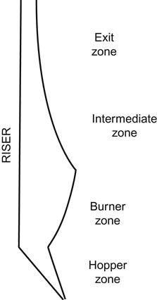
The furnace enclosure should be designed to be capable of withstanding a transient pressure excursion without permanent deformation due to yield or buckling of any support member. The structural stability of the furnace enclosure along with the air supply and flue-gas removal system should be designed to comply with the following recommendations of NFPA 85 to minimize the risk of furnace pressure excursions [2]:
1. Applicable to all boilers (except fluidized-bed boilers):
i. The positive transient design pressure should be at least, but should not be required to exceed, +8.7 kPa (+890 mmwc).
ii. If the test block capability of the forced draft fan at ambient temperature is less than +8.7 kPa, the positive transient design pressure should be at least, but should not be required to exceed, the test block capability of the forced draft fan.
iii. The negative transient design pressure should be at least as negative as, but should not be required to be more negative than, −8.7 kPa (−890 mmwc).
iv. If the test block capability of the induced draft fan at ambient temperature is less negative than −8.7 kPa, the negative transient design pressure should be at least as negative as, but should not be required to be more negative than, the test block capability of the induced draft fan.
2. Applicable to fluidized-bed boiler:
i. The positive transient design pressure should be 1.67 times the predicted operating pressure of the component or +8.7 kPa (+890 mmwc), whichever is greater, but should not be in excess of the maximum head capability of the air supply fan at ambient temperature.
ii. The negative transient design pressure should be the maximum head capability of the induced draft fan at ambient temperature, but not more than −8.7 kPa (−890 mmwc).
3.12 Problems
3.1 Ultimate analysis of a sample of coal was found to contain percentage by weight of following elements:
Calculate the weight of theoretical air for complete combustion of 1 kg of fuel and the weight of products of combustion per kg of fuel burnt.
(Ans.: 11.35 kg of air, 12.31 kg of products of combustion)
3.2 A boiler is fired with a coal having following analysis by percentage weight. The coal is burned using 40% excess air and produces ash containing 25% unburned carbon. Determine
• Volume of air required to burn 1 kg of coal
• Percentage composition of dry products of combustion
(Ans.: 5.60 Nm3/kg, 7.84 Nm3/kg, CO2: 15.02%, SO2: 0.48%, O2: 8.11% and N2: 76.39%)
3.3 In a boiler, air-dried coal with the following percentage ultimate analysis by weight has been used with 50% excess air:
Moles of oxygen per 100 kg of coal
Moles of dry air per kg of coal
Percentage analysis of products of combustion by volume
(Ans.: 5.44 moles of O2 per 100 kg of coal, 0.39 mole of dry air per kg of coal, CO2: 11.76%, H2O: 7.04%, SO2: 0.03%, O2: 6.58% and N2: 74.59%)
3.4 The following is a percentage analysis by volume of dry flue gas. Calculate the air drawn through the furnace per kg of coal fired, given the carbon content of coal is 86.8% by weight.
| Products of combustion | Volume, % |
| CO2 | 11.9 |
| CO | 0.1 |
| N2 | 81.8 |
| O2 | 6.2 |
3.5 Convert the following percentage analysis by volume of dry flue gas to gravimetric analysis.
| Products of combustion | Volume, % |
| CO2 | 10.9 |
| CO | 1.0 |
| N2 | 81.0 |
| O2 | 7.1 |
(Ans.: CO2: 15.97%, CO: 0.93%, N2: 75.53%, and O2: 7.57%)
3.6 For the following gas composition by volume, find out the volume of air required for the combustion of 100 m3 of gas. Determine also the volumetric analysis of the products of combustion.
| Gas composition | Volume, % |
| CH4 | 39.5% |
| H2 | 46.0% |
| CO | 7.5% |
| CO2 | 4.5% |
| H2O | 2.0% |
| N2 | 0.5% |
(Ans.: 504 m3 of air, H2O: 22.63%, CO2: 8.86% and N2: 68.51%)