
Pulverized Coal-Fired Boilers
Pulverized coal firing ensures complete combustion of coal, thus ensuring higher efficiency of steam generators. It is predominantly adopted in large coal-fired utility boilers. The finer the grinding of coal, the more efficient its combustion. The total time required from entry of a coal particle to a furnace to combustion of the particle is very short. This time, however, is dependent on various factors. The heart of a pulverized coal-fired boiler is the pulverizer, also known as the mill. Depending on speed pulverizers are classified as low-speed, medium-speed, and high-speed mills. Pulverized coal burners may be located on the front or opposed walls or in the corners of the furnace. There are two types of fuel-firing systems: bin system and direct-firing system. Coal feeders are either the volumetric or gravimetric type.
Keywords
grinding; combustion; coal size; fineness; volatile matter; HGI; moisture; HHV; YGP index; coal burners; coal feeders
4.1 Brief History
Steam-operated central power stations started operating in the late nineteenth century (1881–1900). Within a couple of decades suspension firing of pulverized coal (finely ground coal particles) was in use at the Oneida Street Power Station, owned by Milwaukee Electric Railway and Light Company, for the first time in a utility [1]. The concept of suspension firing evolved from the belief that if coal were ground to the fineness of flour, it would flow through coal pipes like oil [2] and would burn in the furnace space as easily and efficiently as gas.
By the 1920s, pulverized coal firing became so developed that it resulted in more complete coal combustion and higher system efficiencies. As a result, pulverized coal firing also became attractive to larger boilers. However, it took nearly 5 years for pulverized coal firing to become a dependable method of coal firing for commercial production and utilization of steam. By the 1950s, pulverized coal firing was the main method of coal firing, leading to the construction of large, efficient, and reliable steam generators and power plants.
In pulverized coal firing, fine particles of coal are easily moved by the flow of air and products of combustion through parts of the furnace. Combustion takes place in the furnace space within a very short time (1–2 s) of the presence of particles in the furnace [3]. The process of pulverization includes two stages. In the first stage, raw coal is crushed to a size of not more than 15–25 mm. The crushed coal is then delivered into raw-coal bunkers and transferred to pulverizers, where it is ground to a fine particle size.
4.2 Combustion of Pulverized Coal
Burning a coarse ground coal may reduce the efficiency of the boiler, increase emissions of pollutants, and in certain cases may damage the boiler or its auxiliaries. Efficient combustion of pulverized coal depends on following characteristics of coal [4]:
i. Grinding and abrasion properties
iii. Ignitability and flame stability
As mentioned, when coal is ground to the fineness of flour, the ground coal will flow in pipes like oil and burn in furnace like gas. To arrive at such fineness, it is essential to dry and pulverize the coal using special equipment. Thereafter, other equipment is provided for transporting this dry and pulverized coal to the furnace in an air stream. In addition, another set of equipment is required for injecting this coal along with the air needed for combustion to the furnace.
When combined with air in a furnace, pulverized coal first passes through the stage of thermal preparation, which consists of the evaporation of residual moisture and separation of volatiles. Once these minute particles enter the furnace at a temperature of 1200–1500 K (depending on the type of fuel) and are exposed to heat, their temperature rises and the volatile matter distills off within a fraction of a second. To facilitate transport of pulverized coal, adequate quantity of primary air (20–30% of total combustion air) is introduced at the burner to dry and carry the pulverized coal from pulverizers to the burner or the bin. This air intimately mixes with the stream of coal particles to burn gas resulting from distillation of each particle in the stream [2].
Fuel particles are heated to a temperature 673–873 K at which volatiles are evolved intensively in a few tenths of a second. Volatile matter, mostly hydrocarbons, ignites more easily than the carbon components of the coal, and heating the latter produces coke. The intensive burning of the volatiles takes 0.2–0.5 s [3]. A high yield of volatiles produces enough heat through combustion to ignite coke particles. When the yield of volatiles is low, the coke particles must be heated additionally from an external source.
The final stage is the combustion of coke particles at a temperature above 1073–1273 K. This is a heterogeneous process whose rate is determined by oxygen supply to the reacting surface. Secondary air (70–80% of total combustion air), introduced around the burner, sweeps past and scrubs the hot carbon particles and gradually burns them. The burning of a coke particle takes up the greater portion of the total time of combustion, which may be of the order of 1.0–2.0 s, depending on the kind of fuel and the initial size of particles.
For efficient combustion of pulverized coal two basic factors need to be considered:
a. Pulverized coal must be fed without segregation, and
b. the mixture of pulverized coal and air fed to the burners should permit stable ignition.
For better flame stability the required coal-primary air ratio generally increases with decreasing grindability and decreases with decreasing volatile matter and falling pulverizer loading. Complete burnout of pulverized coal particles depends on physical and chemical properties of the resultant char, individual boiler design, and boiler operating conditions. NOX production from a pulverized coal-fired boiler is dependent on coal characteristics, boiler and burner design, and operating conditions. During combustion of coal particles the reacting mechanism between carbon and oxygen takes place in two stages. Oxygen is adsorbed on the surface of particles and reacts chemically with carbon to form CO. Carbon monoxide then reacts with oxygen within the boundary gas film to get oxidized to CO2 [1].
(The principle of combustion is discussed in Chapter 3, Fuels and Combustion.)
4.3 Pulverizer Performance
The factors that affect pulverizer-grinding performance along with its processing capacity are discussed as follows.
Raw-Coal Size: Normally plants receive run-of-mine coal, although in certain plants washed coal is also supplied. While using run-of-mine coal, it is important to make feed size as uniform as possible, since pulverizer performance is strongly influenced by raw coal size. The smaller the size the better the performance. For small mills top size usually falls between 15 and 25 mm. For medium and large mills, the desired top size of coal may be up to 30 mm and 55 mm, respectively. However, for a particular type of mill, the size of the coal to be used as mill input should conform to the coal size recommended by the manufacturer.
Fineness: Fineness of pulverized coal is extremely important in system design. The higher the fineness of pulverized coal, the lower the pulverizer processing capacity (Figure 4.1).

The degree of fineness of pulverized coal depends to a large extent on coal characteristics. The desired fineness is also determined by the way it affects the coal combustion in the furnace. For pulverized coal testing, the percentage of pulverized coal passing through a sieve of size 50 mesh (which corresponds to a 297 μ opening) is classified as oversize and through a sieve of size 200 mesh (which corresponds to a 74 μ opening) is considered as coal dust [2,5]. For caking coals, pulverization should produce sufficiently fine coal particles to prevent lightweight porous coke particles from floating out of the furnace before completing effective combustion. Free-burning coal, however, does not require the same degree of fineness [2].
To burn pulverized coal successfully in a furnace, the following two requirements must be met:
a. Large quantities of very fine particles of coal, typically 70% of coal that will pass through a 200-mesh screen to ensure ignition because of their large surface-to volume ratios.
b. Minimum quantity of coarser particles, at least 98% of coal that will pass through a 50-mesh screen, to ensure high combustion efficiency.
Note that the percentage of larger coarse particles, of size larger than 50 mesh (297 μ), should not be more than 2% [6], since they cause slagging and loss of combustion.
Volatile Matter: It is known that high-volatile coal ignite more readily than low-volatile coal. Hence, high-volatile coal requires less pulverization than low-volatile coal. Contrary to this, low-volatile coal, except for anthracite, has higher grindability, because it is softer [2]. As a result, the balance between these two characteristics determines the pulverizer output. In practice, with volatile content above 22%, the fineness can be kept between 65 and 70% passing through 200 mesh to ensure ignition stability; while with less than 18% volatile matter content the fineness has to be increased to 80% or above through 200 mesh.
Grindability: This term is used to measure the ease of pulverizing a coal. Unlike moisture, ash, or heating value, this index is not an inherent property of coal [7]. Grindability should not be considered as synonymous with the hardness of coal [7]. Anthracite is a very hard coal, whereas lignite is soft; however, both are difficult to grind.
The hardness of coal is generally in the range 10–70 kg/mm2, depending on rank, with a minimum near 20% volatile matter. Its index is generally given as the Hardgrove Grindability Index (HGI). The higher the index of coal the softer it is to pulverize. It is generally considered that for a desired coal fineness and selected feed size, the mill capacity has a direct relationship with grindability; however, this capacity is significantly influenced by the moisture content of the coal as is evident from Figure 4.2 [8]. If the coal-drying operation is inadequate, the mill capacity is dictated by moisture content and not by grinding. Thus, more output may be available from a mill with a dry coal of lower grindability than with a wet coal of higher grindability.

From the above discussion it is easy to argue that to maintain the same steam-generating capacity, if the moisture content of coal, coal fineness, and feed size remain unchanged, the higher the HGI value, the lower the required pulverizer output. Thus, a higher correction factor should be applied to arrive at correct pulverizer output (Figure 4.3). Reason being pulverizer design capacity is guaranteed under specified HGI value. Deviation from this value will cause a change in design capacity. Hence for deviations from specified HGI value, it is necessary to correct the measured capacity using the correction factor to get the design capacity of the pulverizer.

Moisture: As discussed above the moisture content of coal significantly influences pulverizer performance. It is the surface moisture (SM) that affects pulverization the most; inherent moisture (IM) has little or no effect. If the temperature of the surface moisture in the coal fed to the pulverizer is below its dew point, agglomeration of fines in the pulverizing zone will take place that adversely affect pulverizer capacity. Agglomeration of fines has the same effect as coarse coal during the combustion process. Hence, during the process of pulverization coal must be dried enough to make it free of surface moisture [1].
Hot air is normally supplied for drying of coal inside the pulverizer. If the surface moisture is excessive, the pulverizer must be capable of handling large volumes of high-temperature air. In the event that there is deficiency of hot air or if the pulverizer is unable to handle additional hot air, transport of the pulverized coal to the burners will be reduced. Figure 4.4 shows the relationship between the weight of the air per unit of fuel and the temperature of the coal-air mixture leaving the pulverizer with varying surface moisture for a particular coal.

For high-volatile coal to prevent pre-ignition of dry coal inside the pulverizer, the coal-air mixture temperature at the pulverizer outlet has to be maintained at around 338–348 K, while for low-volatile coal this temperature may be safely raised to 355–373 K. Thus, the supplied air may be pre-heated to a temperature of 600 K or above, as recommended by the manufacturer.
GCV (HHV) of Coal: The heating value of coal also influences the pulverizer output. Pulverizer design output is guaranteed under certain specified GCV. Any deviation in GCV will cause a change in design output. Hence for deviations in GCV, it is imperative to correct the measured output using the correction factor to get the design output. For maintaining the same steam generating capacity, the higher the heating value, the lower the required pulverizer output. Hence, a higher correction factor should be applied to arrive at the correct pulverizer output as is evident from Figure 4.5.

Abrasive Index (YGP – Yancy, Geer, and Price – Index): Pulverizing results in an eventual loss of grinding-element material. Balls, rolls, rings, races, and liners gradually erode and wear out as a result of abrasion and metal displacement in the grinding process. The wear rate is linearly related to the mineral content of coal. Two basic mechanisms of mechanically induced wear are present in the grinding zone. The first mechanism is abrasion and the second basic mechanism is impaction erosion wear, the effect of which is considered to be negligible. The YGP Index typically indicates the abrasive characteristic of coal. Figure 4.6 presents a typical “wear life curve” of a pulverizer.

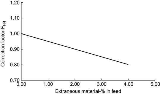
Extraneous Materials: The wear life of pulverizer-grinding rings, balls, etc., is influenced by coal-feed size, HGI, and the presence of extraneous materials such as rock, slate, sand, stone, pyrite, quartz, etc., which are quite abrasive. The effect of coal-feed size (larger than 25 mm or so) on wear rate is small. Wear rate is greatly influenced by quartz and pyrite particles. High quartz content in ash would exacerbate the wearing characteristics of grinding parts but not mill capacity. The larger the size of these particles, the longer they remain in circulation in the mill, hence wear rates are increased. Quartz, with a density of approximately twice that of coal, has to be ground to a finer size when compared to the coal particles before it is released out of the pulverizer by the primary air. Rounded quartz particles cause higher wear than that resulting from angular particles. Quartz causes a three- to four-fold increase in abrasion over siderite (a mineral composed of FeCO3), which in turn is about three times more abrasive than calcite (a carbonate mineral and the most stable polymorph of CaCO3).
The wear life of the pulverizer-grinding components is adversely affected by the presence of rock and stones (typical Moh’s scale of hardness 6), which cause five times the wear caused by coal (typical Moh’s scale of hardness 3). Hence, a lower correction factor should be applied to arrive at correct pulverizer output for a coal containing a higher quantity of extraneous materials as presented in Figure 4.7.
Pulverizers also suffer from chemical wear, i.e., corrosion, in a moist atmosphere. Sulphur (oxidized pyrite) and chlorine (chloride and sodium ion) compounds and organic acids are comprised of an acidic and corrosive medium in moist coal. Furthermore, moisture in the absence of acids can enhance abrasion wear.
4.4 Coal Burners (Figure 4.8)
After pulverization, coal is transported pneumatically to the burners through pipes. Air and fuel are supplied to the furnace in a manner that permits:
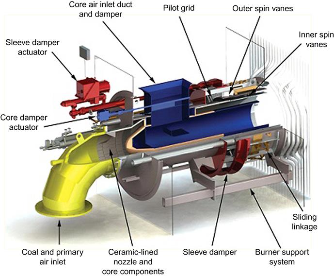
The air that transports coal to the burner is called the primary air, while secondary air is introduced around or near the burner. The burners impart a rotary motion to the coal-air mixture in a central zone, and the secondary air around the nozzle – all within the burner. The rotary motion provides pre-mixing for the coal and air along with some turbulence.
In steam generators burners may be installed on a front wall or on front and rear (opposed) walls or on furnace corners. Front-wall burners are provided with either internal ribs or circular registers that impart a rotary motion to coal-air mixture that produces turbulence. Opposed-wall burners throw their flames against each other to increase turbulence. Tangential or corner-fired burners produce inherently turbulent flame.
The total air-fuel ratio in coal burners is much greater than the stoichiometric requirement but just enough to ensure complete combustion without wasting energy by adding too much sensible heat to the air. The initial ignition of coal burners is accomplished with the help of a sustained flame of light fuel-oil burner. The control equipment of coal burners ranges from manual to a remotely operated programmed sequence. (Detailed treatment on the design aspects of burners is given in Chapter 3, Fuels and Combustion.)
4.5 Pulverizer System Design
NFPA 85 recommends the pulverizer system arrangement should be such as to provide only one direction of flow, i.e., from the points of entrance of fuel and air to the points of discharge. The system should be designed to resist the passage of air and gas from the pulverizer through the coal feeder into the coal bunker. To withstand pulverizer-operating pressures and to resist percolation of hot air/gas, a vertical or cylindrical column of fuel at least the size of three coal-pipe diameters should be provided between the coal-bunker outlet and the coal-feeder inlet as well as between coal-feeder outlet and the pulverizer inlet. Within these cylindrical columns there will be accumulation of coal that will resist percolation of hot air/gas from the pulverizer to the coal bunker. All components of the pulverized coal system should be designed to withstand an internal explosion gauge pressure of 344 kPa [9].
Besides the above, design specifications of a pulverizer system must also consider the following:
Number of Spare Pulverizers: To overcome forced outage and consequent availability of a number of operating pulverizers it is generally considered that while firing the worst coal one spare pulverizer should be provided under the TMCR (Turbine Maximum Continuous Rating) operating condition. In certain utilities one spare pulverizer is also provided even while firing design coal, but under the BMCR (Boiler Maximum Continuous Rating) operating condition. Practice followed in the United States generally is to provide one spare pulverizer for firing design coal, in larger units two spare pulverizers are provided. However, provision of any spare pulverizer is not considered in current European design [5].
Pulverizer Design Coal: The pulverizer system should be designed to accommodate the fuel with the worst combination of properties that will still allow the steam generator to achieve the design steam flow. Three fuel properties that affect pulverizer-processing capacity are moisture, heating value, and HGI, as discussed earlier.
Pulverizer Product Fineness: Fineness of pulverized fuel is one of the pulverizer sizing criteria, as discussed earlier.
Unit Turndown: The design of a pulverizer system determines the turndown capability of the steam generator. The minimum stable load for an individual pulverizer firing coal is 50% of the rated pulverizer capacity. Normally in utility boilers, the operating procedure is to operate at least two pulverizers to sustain a self-supported minimum boiler load. Thus, the minimum steam generator load when firing coal without supporting fuel is equal to the full capacity of one pulverizer. Therefore, a loss of one of the two running pulverizers will not trip the steam generator because of “loss of fuel” and/or “loss of flame.”
Pulverizer Wear Allowance: A final factor affecting pulverizer system design is a “capacity margin” that would compensate for loss of grinding capacity as a result of wear between overhauls of the pulverizer (Figure 4.6). A typical pulverizer-sizing criterion is 10% capacity loss due to wear.
4.6 Classification of Pulverizers
A pulverizer, also known as a grinding mill, is the main equipment associated with a pulverized coal-fired boiler. Grinding inside a pulverizer is realized by impact, attrition, crushing, or a combination of these. Based on their operating speed, pulverizers/mills are classified as “low,” “medium,” and “high” speed mills [10]. Depending on the pressure existing inside the grinding zone, pulverizers may be categorized as the suction type or the pressurized type. For both types, the pulverizing of coal is accomplished in the following two stages:
Feeding System: This system must automatically control fuel-feed rate according to the boiler-load demand and the air rates required for drying and transporting pulverized coal to the burner.
Drying: One important property of coal being prepared for pulverization is that it has to be dry and dusty.
4.6.1 Low-speed mill
Mills operating below 75 rpm are known as low-speed mills. Low-speed units include ball or tube or drum mills, which normally rotate at about 15–25 rpm. Other types of mills, e.g., ball-and-race and roll-and-race mills, that generally fall into the medium-speed category may also be included in this category provided their speed is less than 75 rpm.
Tube mills (Figure 4.9), also known as ball mills, are usually a drum-type construction or a hollow cylinder with conical ends and heavy-cast wear-resistant liners, less than half-filled with forged alloy-steel balls of mixed size. This is a very rugged piece of equipment, where grinding is accomplished partly by impact, as the grinding balls and coal ascend and fall with cylinder rotation, and partly by attrition between coal lumps inside the drum.

Primary air is circulated over the charge to carry the pulverized coal to classifiers. In this type of mill pulverized coal exits from the same side of the mill that solid coal and air enter. In some designs entry of solid coal air and exit of pulverized coal are provided at each end of the mill. Both ends of the mill are symmetrical in nature. Consequently, each mill is served by two coal feeders.
Reliability of this type of mill is very high and it requires low maintenance. The disadvantages of this type of mill are high power consumption, larger and heavier construction, greater space requirement, etc. To pulverize coal of high rank and low grindability, ball/tube mills are preferred because they can achieve high fineness, required for proper burning, and maintain high availability.
4.6.2 Medium-speed mill
This type of pulverizer is usually one of two types: ball and race and roll and race. The speed of the grinding section of these mills is usually between 75 and 225 rpm. Medium-speed mills are smaller than low-speed units and are generally the vertical spindle type. They operate on the principles of crushing and attrition. Pulverization takes place between two surfaces, one rolling on top of the other. The rolling elements may be balls or rolls that roll between two races, in the manner of a ball bearing. Primary air causes coal feed to circulate between the grinding elements, and when it becomes fine enough, it becomes suspended in air and the finished product is conveyed to the burners or the classifier depending up on the applicable system. Configuration of vertical spindle mills may be either the pressurized type with a cold/hot primary air fan or the exhauster type. Medium-speed mills require medium to high maintenance, but their power consumption is low.
Ball and Race Mill (Figure 4.10): In the ball-and-race mill, balls are held between two races, much like a large ball bearing. The top race or grinding ring remains stationary while the bottom race rotates. As the coal is ground between large diameter balls and the ring, the balls are free to rotate on all axes and therefore remain spherical. Grinding pressure is adjusted by controlling the tension of springs.

Roll and Race Mill: The grinding elements of this type of mill consist of three equally spaced, spring-loaded heavy conical (Figure 4.11) or toroidal rolls (Figure 4.12), which, suitably suspended inside near the periphery, travel in a concave grinding ring or bowl (with heavy armoring). Force is applied to the rolls from above by a uniformly loaded thrust ring. The main drive shaft turns the table supporting the grinding ring, which in turn transmits the motion to the rollers.


Mills with conical rolls are also known as bowl mills. As the coal is ground between large diameter rolls and the bowl, rolls revolve about their own axes, and the grinding bowl revolves about the axis of the mill.
In the toroidal rolls type, grinding occurs only under the rollers in the replaceable grinding ring. There is no metal-to-metal contact between grinding elements, since each roller rests on thick layer of coal. Thus the maintenance is minimized.
4.6.3 High-speed Mill (Figure 4.13)
High-speed mills were developed during the early days of pulverized fuel firing. These mills are either hammer beater or attrition mills, which operate at speeds above 225 rpm. The beaters revolve in a chamber equipped with high-wear-resistant liners. Both impact and attrition is combined in this mill to pulverize coal, which is pulverized by the rubbing of coal on coal, by the impact of coal on impeller clips, and also by being rubbed between pegs. A classifier returns the coarse coal particles for further classification. Its capital cost per unit output is low, it requires minimum space, there is no speed reducer between the drive and the pulverizer, and its parts are lightweight to facilitate maintenance. Its maintenance cost, however, is very high, which is the reason this type of mill has long been discontinued from service. This type of mill is mostly used with low-rank coal with high moisture content, e.g., lignite, and uses flue gas for drying.

4.7 Coal Preparation Systems
There are two basic types of fuel preparation systems, the bin system and direct firing system, that have been used for the processing, distributing, and burning of pulverized coal.
4.7.1 Bin System (Figure 4.14)
In the bin system coal is processed at a location away from the furnace, and the coal is pulverized in pressurized or suction type mills. The drying and conveying of coal is done by hot air or hot flue gas extracted from the boiler. The resulting pulverized coal-primary air mixture is pneumatically conveyed to a cyclone separator and/or fabric bag filter that separate and exhaust the moisture laden air to the atmosphere and discharge the pulverized coal to a pulverized coal bunker/bin near the furnace.

The stored coal from the pulverized coal bunker is fed to the burners through the respective pulverized coal feeders and conveyed by primary air. Additional vapor burners are provided in this system to burn the escaping coal dust (2–3%) after the cyclone separators. The basic advantage of this system is that the pulverization is not tied up with the minute-to-minute operations of the boiler and the system can withstand the outage of the pulverizer to a certain extent, depending upon the storage capacity available. The disadvantages are intrinsic dust nuisance of installation, fire risk of pulverized coal storage, higher cost of pulverization, etc. It is essential to incorporate an additional fire-prevention system and dust-coal disposal system to prevent unforeseen boiler outages.
The bin system was widely used before pulverizing equipment reached the stage where it was reliable enough for continuous steady operation.
For successful operation, the following guidelines need to be adhered to:
i. Surface moisture in the pulverized coal must not exceed 3%.
ii. Fineness should not be less than 90% through a 50-mesh sieve.
Because of the many stages of drying, storing, transporting, etc., the bin system is subject to fire hazards from spontaneous combustion. Nevertheless, it is still in use in many older plants.
4.7.2 Direct Firing System (Figure 4.15)
The bin system has been overshadowed by the direct-firing system because of greater simplicity, lower initial investment, lower operating costs, less space requirement, and greater plant cleanliness. The pulverizing equipment developed for direct-firing systems permits continuous utilization of raw coal directly from the bunkers through a feeder, pulverizer, and primary-air fan, to the furnace burners.

There are two direct-firing methods in use – the pressure type, where the primary-air fan is located at the pulverizer inlet, and the suction type, where the primary-air fan is located downstream the pulverizer. In either type, the coal is delivered to the burners with air as the transport medium.
The advantages of the direct firing system are:
The only disadvantage of this system is any outage in the pulverizer system immediately affects unit output, even though spare pulverizers are usually provided. Fuel feed is regulated to load demand by a combination of controls on the feeder and the primary-air fan to give fuel-air ratios in accordance with variations in steam generation. Large steam generators are provided with more than one pulverizer system, each feeding a number of burners, so that a wide control range is possible by varying the number of pulverizers and the load on each.
4.8 Coal Feeders
Coal from the raw-coal bunker is fed to the pulverizer through a raw-coal feeder or simply the coal feeder. The function of a coal feeder is to control the flow of coal to the pulverizer to comply with the demand of steam generation. In general, there are various kinds of raw-coal feeders in use, e.g., table type, overshot roll type, belt type, drag-link type, etc. Coal flows from raw coal bunker on to a moving belt through a vertical pipe, and from this belt coal flows to a pulverizer through another vertical pipe.
In most cases, coal feeders are driven by a constant speed electric motor through step-less variable speed drives to control the coal flow. The variable speed is generally achieved through positive infinitely variable (PIV) gears, variable hydraulic or electro-magnetic coupling, variable frequency drive, or some sort of variable stroke clutch mechanism.
Feeders may be the volumetric type, maintaining a constant speed vs. volume (for the same bed thickness) relationship or the gravimetric type with advanced electronic controls, capable of automatic control and recording of mass flow of coal feed.
The roll feeder and the belt feeder may be considered a highly efficient volumetric feeding device. In a volumetric system (Figure 4.16) the flow of coal is controlled by the boiler demand system with the help of a fixed position-leveling bar in combination with a variable speed belt, but the actual amount fed is estimated and the accuracy can vary greatly.

For efficient operation of the plant, however, it is essential to know the exact amount of fuel being fed. The gravimetric feeder (Figure 4.17) does this by determining the product of the fuel belt load multiplied by the speed to give the actual flow rate. This flow rate is compared to the boiler set point and the belt speed is varied accordingly. The first installation of gravimetric feeder was placed in continuous operation at Niagara Mohawk Power Corporation’s Dunkirk Station in 1957 [11]. The benefits of gravimetric feeding are:
i. Exact and constant amount of coal feed to the mill
ii. Saving of coal due to exact control of excess air

Two different types of gravimetric coal feeder generally used in the industry are the Stock® gravimetric feeder and the Pfister rotor weighfeeder. The Stock gravimetric coal feeder weighs material on a length of belt between two fixed rollers (span) precisely located in the feeder body. A third roller, located midway in the span and supported at each end by precision load cells, supports half the weight on the span. As material passes over the span, the load cell generates an electrical signal directly proportional to the weight supported by the center roller.
The Pfister rotor weighfeeder works like a horizontal star feeder. The gravimetric coal mass in the feeder is measured by a load cell. The speed of the feeder motor is controlled inverse to the coal content in the feeder. Less coal in the feeder results in higher speed, and more coal in the feeder results in lower speed. The outcome is a highly accurate feed rate at the outlet.