Chapter 3. Selections: The Key to Compositing
There is no abstract art. You must always start with something. Afterward you can remove all traces of reality.
—Pablo Picasso
A particle physicist works with atoms, bakers and bankers each work with their own form of dough, and compositors work with selections—many different types of selections, even thousands, each derived one at a time.
If compositing were simply a question of taking pristine, perfect foreground source A and overlaying it onto perfectly matching background plate B, there would be no compositor in the effects process; an editor could accomplish the job before lunchtime. Instead, compositors break sequences of images apart and reassemble them, sometimes painstakingly, first as a still frame and then in motion. Often, it is one element, one frame, or one area of a shot that needs special attention. By the clever use of selections, a compositor can save the shot by taking control of it.
This chapter focuses on how a layer merges with those behind it. Then Section II of the book, “Effects Compositing Essentials” (in particular Chapters 6 and 7), examines specific ways to refine selections, create high-contrast mattes, and pull color keys (aka greenscreen mattes).
Methods to Combine Layers
You may already be familiar with all of the ways to create layer transparency or the effect of one layer blended with another, but it’s worth a look just to be certain you’re clear on all of the options in After Effects to begin with.
Mattes
In his book CG 101: A Computer Graphics Industry Reference, author Terrence Masson defines a matte as “a grayscale single-channel image used to hold out a portion of a composite element when it is placed over a background plate... The pixel values of a matte channel therefore represent the opacity of the corresponding image data.”
As you know, After Effects uses a layer-based metaphor similar to that of Photoshop (and of the two, After Effects had them first). Many users of both apps are first introduced to mattes by beginning with elements that have mattes already included; they can also be created by keying out the green background from a visual effects shoot (Figure 3.1), but there are other ways to procedurally generate a matte, such as a high-contrast or hi-con matte using carefully manipulated luminance data. Chapter 6 goes into depth about these processes; for now, this overview offers a basic working understanding.
Figure 3.1. This split-screen image shows a blue-screen shoot (left) and the resulting matte.
Alpha Channel
An alpha or transparency channel is a specific type of matte that can be contained within an imported image; with computer-generated images the alpha channel is generated as part of the rendering process itself. After Effects itself can, of course, also create alpha and transparency channels in rendered images (Figure 3.2).
Figure 3.2. A computer-generated baseball’s color and alpha channels.

Like Photoshop but unlike many other compositing applications, After Effects has a persistent concept of a fourth alpha or transparency channel alongside three channels of color data. After Effects assumes (also unique from other compositing apps) that edge premultiplication is automatically removed before image combination or manipulation is begun. Internally then, all alphas in After Effects are processed as straight (see Chapter 1 for a review of how interpretation is determined on import). This is natural enough, but can occasionally become inflexible to anyone who actually comprehends transparency and edge multiplication and wants to manage them directly.
Notes
![]()
The built-in assumption of unmultiplied edge pixels can, in some cases, make life more difficult should things not go as planned. The “Alpha Channels and Edge Multiplication” section later in this chapter offers the lowdown on changing edge multiplication midstream.
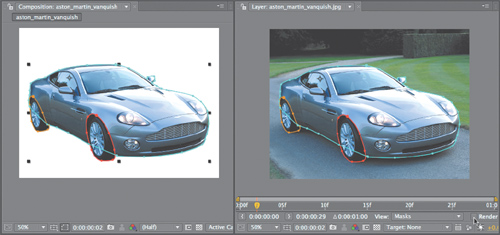
Mask
A mask in After Effects is a shape made up of points and vectors (Figure 3.3). As a vector shape, it can be infinitely scaled without losing any definition, but as it is generally drawn by hand, hand-animating the selection (a process known as rotoscoping, detailed in Chapter 7) is much more involved than generating a matte procedurally.
Figure 3.3. This split-screen view shows the garbage matte mask that was added to remove areas of the stage not covered by the blue screen.

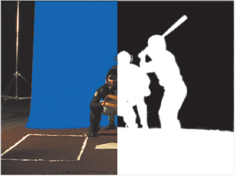
There are also now several automated methods (Figure 3.4) to create animated selections by tracking raster data (pixel values):
Figure 3.4. Before the introduction of Roto Brush (top), which analyzes pixels from user-generated brushstrokes, the closest thing to automatic mask generation in After Effects was Auto-trace, which uses simple luminance criteria to generate masks—lots of them, as is apparent from all the colored outlines (bottom).
• Roto Brush— this much talked-about feature added to After Effects CS5 can automatically generate and track an animated mask. The advantages are that it works well and can be automatically tracked; however, it is far from perfect and the result is its own effect-based selection instead of a standard After Effects mask. You’ll read more about this in Chapter 7.
• mocha shape— a shape tracked in mocha for After Effects can be brought in and applied using the mocha Shape plug-in. It is capable of automatically generating a mask that can include per-vertex feathering in many (but by no means all) situations. Mocha shape is also an effect-based selection tool incompatible with the standard After Effects mask. More on this in Chapters 7 and 8.
• mocha-AE Copy/Paste— it’s also possible to copy a shape tracked in mocha-AE and paste it directly into After Effects as a mask shape. This offers most of the advantages of mocha shape (other than per-vertex feathering), and because it is applied as mask data it integrates with all of the many effects and plug-ins that rely on selections in that format. More on this in Chapters 7 and 8.
• Layer > Auto-trace— While technically impressive, Auto-trace is problematic as a selection tool because it typically creates dozens of masks on any but the simplest live-action shot. It also offers less control than the other methods, so there are only benefits if you want to do something stylized (motion graphics) with those masks. If this has a use for effects compositing, I haven’t found it.
Blending Modes
Blending modes (Add, Screen, Multiply, Difference, and so on) do not, by and large, generate alpha channel transparency; most apply a specific mathematical formula to the compositing operation of a given layer. They are essential to re-create the phenomena of real-world optics.
For example, when compositing an element that is made up more of light or shadows than reflective surfaces, such as fire shot in a blackout environment, it is vital to use blending modes instead of a luminance matte—don’t try keying out the black (see Chapter 14 for more details). You can, of course, use selections combined with blending modes to get the best of both worlds. Blending modes—which to ignore, which are essential, and how to use them—are discussed in depth later in this chapter.
Effects
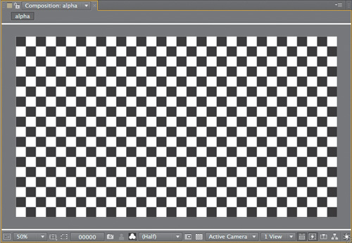
Effects and plug-ins can also generate transparency: some (such as Levels and Curves) by offering direct adjustment of the alpha channel, others (in the Channel folder) by creating or replacing the alpha channel. Some even generate images from scratch that may include an alpha channel (Figure 3.5).
Figure 3.5. The Checkerboard effect is one of a few that is generated in the alpha channel (displayed here) by default.
Combined Selection Techniques
An ordinary effects shot may use more than one, or even all, of the above techniques. Suppose you have greenscreen footage (say a stylish Ford GT40) and want to replace the number on the side. You might key out the greenscreen to create a matte channel for the car, import the number decal via a Photoshop or Illustrator file with an alpha channel or other transparency data already included, create masks for the areas you couldn’t key (such as where the wheels make contact with the floor), blend in some smoke coming out of the exhaust with layers using Add and Multiply modes, and create some heat ripple using a Displacement Map effect (Chapter 14).
The art is in knowing which approach to apply in a given situation, and for this there is no substitute for knowledge of how they operate.
Optics and Edges
What exactly is happening in a simple A over B composite? In After Effects, it seems nearly as natural as laying one object on top of another does in the real world. In most other compositing applications even A over B is an individualized compositing operation, and that is closer to the truth—a truth that After Effects obscures in order to make the process easier. Not only that, but there is more to what is going on than might be obvious, because of the phenomena of optics. The four stages of image gathering and viewing—the physical world itself, camera optics, human vision, and the display device and its environment—exhibit phenomena that are interdependent.
As a compositor, you are not supposed to re-create actual reality, but instead the way the camera (and the eye) gathers visual data from the world. This affects something even so fundamental as how the edges of objects should look in order for the eye to accept them as believable.
Close-up: The Compositing Formula
![]()
The act of laying one object on top of another is so natural—A over B—it’s hard to remember that re-creating this phenomenon on a computer means that something mathematically sophisticated occurs wherever there is transparency. The foreground pixel values are first multiplied by the percentage of transparency, which, if not fully opaque, reduces their value. The background pixels are multiplied by the percentage of opacity (the inverse of the foreground layer’s transparency), and the two values are added together to produce the composite. Expressed as a formula, it looks like
(Fg * A) + ((1–A)*Bg) = Comp
With real RGB pixel data of R: 185, G: 144, B: 207 in the foreground and R: 80, G: 94, B: 47 in the background, calculating only one edge pixel would look like
[(185, 144, 207) 3.6] + [.4 3(80, 94, 47)] = (143, 124, 143)
The result is a weighted blend between the brightness of the foreground and the darker background.
Other effects compositing programs, such as Nuke or Shake, do not take this operation for granted the way that After Effects and Photoshop do. You can’t simply drag one image over another in a layer stack—you must apply an Over function to create this interaction.
This is not a disadvantage of After Effects—it actually makes basic compositing simpler and faster—but it can obscure important related details such as edge pixel premultiplication (detailed later in this chapter).
Bitmap Alpha
A bitmap can be defined as an image made up of pure white or black pixels (ones and zeroes, if you will), and a bitmap selection is made up of pixels that are either fully opaque or fully transparent. This is the type of selection generated by the old Magic Wand tool in Photoshop. You can feather or blur the resulting edge, but the initial selection contains no semitransparent pixels.
This type of selection may have an occasional use, but it truly belongs to the world of primitive computers, not complex nature (or optics). An edge made up of pixels that are either fully opaque or invisible cannot describe a curve or angle smoothly, and even a straight line looks unnatural in a natural image if it completely lacks edge thresholding (Figure 3.6).
Figure 3.6. This bitmap image contains no threshold pixels. Compare this result with that of Figure 3.7 to see how your monitor displays a curved shape.

Feathered Alpha
Although it’s easy enough to see that a bitmap edge does not occur in nature, it’s hard to imagine that hard objects should have transparent, feathered edges. Look around you at the edges of hard-surface items; they appear sharp.
But study an image of the same thing more closely, and you’ll find some degree of edge softness. Adding softness, threshold, or “feather” to an edge approximates this softness in the hard digital world of single pixels, which are square and either on or off. Properly feathered edges can
• approximate organic curves (Figure 3.7); we’re used to this in raster images—digital images made up of pixels
Figure 3.7. Zoom in far enough on a diagonal or curve and you see square pixels, yet further away your eye accepts the illusion.

• mimic the natural behavior of optics; edges rarely are 100% sharp
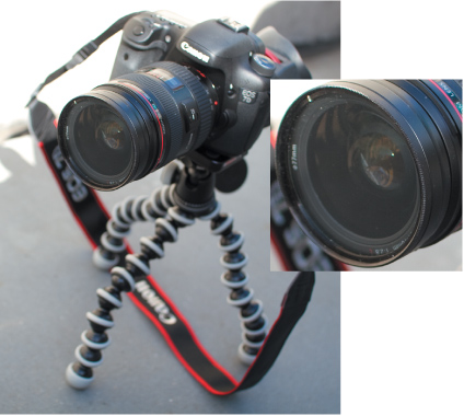
Optics can be observed in any photo with no compositing whatsoever (Figure 3.8). Viewed close up, areas at the edge of objects become a fine wash of color combining the foreground and background. This is not due to inaccuracy in the camera; it is what happens to light as it travels around objects in the physical world and then through the lens of the camera (or your eye).
Figure 3.8. Shallow depth of field causes most of the edges in this image to appear soft, but even where the subject is in perfect focus (inset) the edge displays surprising characteristics where it meets the defocused background. Lesson? A soft edge is not necessarily a mistake, since nature never makes any of those.
Opacity
Transparent foreground objects transmit light, and After Effects is designed to mimic the way they behave when layered together. Take two identical layers, with no alpha or transparency information for either layer. Set each layer to 50% opacity, and the result does not add up to 100%. Here’s why.
Tip

Ctrl+Alt (Cmd+Opt) and the + or – key raises or lowers layer opacity by 1%. As everywhere in After Effects, add the Shift key and the increment is 10x or 10%.
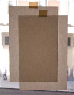
Figure 3.9 shows light filtering through two overlapping sheets of paper. (No expense is spared bringing you these real-world simulations.) Let’s suppose that each sheet is 75% opaque; 25% of the background light passes through. Add a second sheet and 25% of 25%—roughly 6%—passes through both layers. It’s not a lot of light, but it’s not zero; it would take a few more layers of paper to block out the light completely.
Figure 3.9. Although a single sheet of paper is more than 50% opaque, two sheets of paper layered one on top of another are not 100% opaque. This is how overlapping opacity is calculated in After Effects.
Notes
![]()
The After Effects model of combining opacity values fractionally, instead of simply adding the values together, is not how it’s handled in most other compositing applications, and it takes even some veterans by surprise.
After Effects re-creates this behavior, adding fractional and not whole opacity values of two or more layers. It’s Zeno’s paradox—you are only getting a fraction of the way closer to the destination of 100% opacity when stacking layers whose opacity is less than 100.
Transparency: Alpha Channels and Edge Multiplication
One major source of confusion with After Effects has to do with its handling of alpha channels and edge multiplication against a unified background color, also known as premultiplication. After Effects has a persistent concept of the alpha channel as part of every image, and this channel is always expected to be unmultiplied within After Effects, whether it originated that way or not.
Any color multiplied into edge pixels is to be removed upon import (in the Alpha section of the Interpret Footage dialog), and reintroduced only on output. Provided those Alpha settings are correct, this works surprisingly well. At some point, however, you may need to better understand how to take control of edge multiplication within After Effects.
Close-up: How Edge Multiplication Works
![]()
Imagine the background value to be 0,0,0 or solid black; an edge pixel is multiplied by 0 (making it pure black) and then added back to the source, in proportion to the amount of transparency in the alpha channel pixel. Removing edge multiplication with the Premultiplied setting subtracts this extra black from those edge pixels.
Premultiplication Illustrated
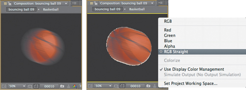
Premultiplication exists for one reason only: so that rendered images have realistic, anti-aliased edges before they are composited. Figure 3.10 (left) shows an image rendered against black without edge multiplication; it just doesn’t look very nice. Figure 3.10 (right) looks more natural, but the edge pixels are now mixed with the background color and must effectively be un-composited from it before they are composited against some other image.
Figure 3.10. The purpose of premultiplication is principally so that images rendered against black, such as this motion-blurred basketball from Chapter 2 (left), appear natural by blending the semi-transparent edge pixels. You have the option to choose RGB Straight under the Channel menu and view the image the way After Effects works with it (right).
When you ask After Effects to “guess” how to interpret the footage (on import, by choosing Guess in the Interpret Footage dialog, or pressing Ctrl+Alt+G/Cmd+Opt+G), it looks for sections of uniform color that are mixed into edge pixels, indicating that the correct setting is Premultiplied.
Notes
![]()
Most computer-generated images are premultiplied, unless specific steps are taken to counteract the process. The Video Output section of the Output Module settings for items in the Render Queue includes a menu to specify whether you render with Straight or Premultiplied alpha; by default, it is set to Premultiplied.
Back in Chapter 1, Figure 1.13 presented the same foreground image with two alpha interpretations, one interpreted correctly, the other not. A misinterpreted alpha either fails to remove the background color from the edge pixels or does the opposite, removing shading that should actually be present.
You may find that fringing appears in your comps despite your careful managing of the alpha channel interpretation on import. This does not indicate some bug in After Effects, but rather a mystery you must solve. There are two basic ways it can occur:
Notes
![]()
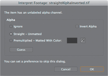
After Effects attempts to guess not only the setting but the background color of a premultiplied image; generally this is black or white, but watch out for situations where a 3D artist has become creative and rendered against canary yellow or powder blue. This is bad form, but it’s also the reason there is an eyedropper adjacent to the Matted With Color setting (Figure 3.11).
Figure 3.11. Be careful here: Many experienced artists assume that After Effects has already made a guess (here, Straight) when it is merely using whatever was set the last time. It’s better to find out what the correct setting is from the application (or artist) that created the image and set this yourself.
• An alpha channel is misinterpreted in Interpret Footage.
• Edge multiplication can materialize within After Effects, probably unintentionally, when a matte is applied to a layer that has already been comped against black.
Unfortunately, artists who misunderstand the underlying problem will resort to all sorts of strange machinations to fix the black edge, ruining what may be a perfectly accurate edge matte.
Get It Right on Import
Preferences > Import > Interpret Unlabeled Alpha As determines what happens when footage with an unlabeled alpha channel is imported; the default is Ask User.
The Ask User dialog has three choices, one of which is checked, and a Guess button (Figure 3.11). This is confusing, as it seems as if After Effects has already guessed, when it has not: It is merely using whatever was set the previous time.
The Guess option is not accurate 100% of the time; if the foreground and background are similar, it can be fooled. Ideally you will work on a project whose images are consistent (in terms of edge multiplication and background color); in that case, you can set an Import preference. Typically, however, it’s best to be able to find out from whoever created it whether the source contains edge multiplication and what settings to use.
When that’s not possible, examine the image and look for the symptoms of a misinterpreted alpha: dark (or bright) fringing in the semi-opaque edges of the foreground.
Tip
RGB Straight (Alt+Shift+4/Opt+Shift+4 or use the Show Channel menu at the bottom of a viewer panel) displays the image in straight alpha mode, as After Effects views it internally.
Solve the Problem Internally
The really gnarly fact is that premultiplication errors can be introduced within a composition, typically by applying a matte to footage that is already somehow blended—multiplied—with a background.
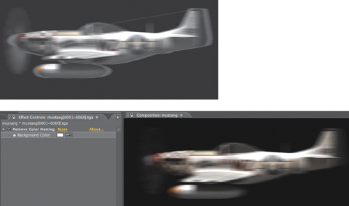
If you see fringing in your edges, you can try the Remove Color Matting effect (Figure 3.12). This effect has one setting only, for background color, because all it does is apply the unpremultiply calculation (the antidote to premultiplication) in the same manner that it would be applied in Interpret Footage.
Figure 3.12. The plane was matted against a white background, but transparency has been applied via a track matte (the equivalent of a straight alpha), so white fringing appears against black (top). Remove Color Matting, with Color set to pure white, corrects the problem (bottom), but only when applied to a precomp of the image and matte.
An even better option in cases where you have an element against black and no alpha channel is to use the Channel Combiner effect, with Max RGB as the From value and Alpha Only as the To value. Follow this with the Remove Color Matting effect. This one-two punch uses black areas of the image to create transparency and removes the multiplied black from the resulting transparent pixels. You can save it by choosing Animation > Save Animation Preset.
Tip
The Remove Color Matting effect will not work properly on a layer with a track matte; be sure to precompose the layer and its track matte prior to applying Channel > Remove Color Matting.
Mask Modes
Masks in After Effects are an available part of any layer (provided it’s not a camera, light, or null object); just twirl down the layer in the Timeline and there they are. These are vector shapes that you draw by hand, and they are the fundamental method used to hand-animate a selection. There are five basic shapes (the Q key cycles through them) and the Pen tool (G) for drawing free-form.
Notes
![]()
Shape layers are directly related to masks; they are drawn with the same tools. If a layer that can receive a mask is selected, then After Effects draws a mask; otherwise, it creates a new Shape layer.
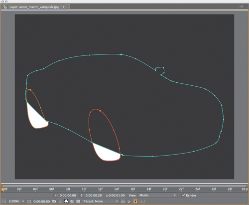
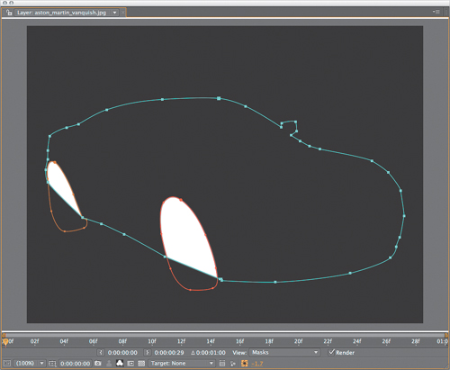
You can draw a mask in either the Composition or Layer viewer. In Layer viewer the source image persists in its default view; there is a Render toggle next to the Masks selection in the View menu to disable all mask selections. Artists may want to see a masked layer in the context of the comp but find it difficult to adjust the mask in that view—in such a case, the Layer and Composition views can be arranged side by side (Figure 3.13).
Figure 3.13. With the Composition and Layer panels side by side, you can leave the mask enabled in the Composition panel but uncheck Render in the Layer panel.

When you draw a mask directly in the Composition viewer, a selection is created as soon as the shape is closed (which is how it begins unless you create it point by point with the Pen tool). This allows you to examine the selection in situ, but it conceals anything you might have missed. If the layer is rotated in 3D space, the mask shape is also rotated.
If you cannot see what you’re doing in the Composition viewer, switch to the Layer viewer and, if necessary, uncheck Render at the bottom to disable the mask in this view (but not in the comp itself). When using any mask shape tool it’s possible to
• double-click the tool (in the Tools panel) to set the boundaries of the mask shape to match those of the layer
• press Shift to constrain proportions when drawing or scaling
Tip
Mask shapes can be edited to create more precise custom shapes; for example, you can make a half-circle by deleting one vertex and adjusting two vertices of an ellipse.
• use Ctrl (Cmd) to draw from the center (with the Rectangle, Rounded Rectangle, and Ellipse tools)
• click Shape under Mask Path (M) in the Layer Switches column to open the Mask Shape dialog; here you can enter exact mask dimensions
• double-click the shape with the Selection tool to activate Free Transform mode, then
• Shift-drag on a corner to scale the mask proportionally
• Shift-drag an outside corner to snap rotation to 45-degree increments
• Shift-drag anywhere else to transform on one axis only
• press the M key twice, rapidly, to reveal all Mask options for the selected layer
• press the F key to solo the Mask Feather property—feather is applied everywhere equally on the mask, equidistant inward and outward from the mask shape
Notes
![]()
Easter egg alert! Simpsons fans, try this: Hold Ctrl+Alt+Shift (Cmd+Opt+Shift) and click on Mask Expansion. The property disappears. Now enter MM for a humorous reference to Season 3, Episode 13.
• use the Mask Expansion property to expand or (given a negative value) contract the mask area; two masks can be used together, one contracted, one expanded, to create an edge selection
Chapter 7 offers more specifics about drawing precise masks; big, soft masks are referenced throughout the book for all kinds of lighting, smoke, and glow effects (Figure 3.14).
Figure 3.14. A series of layers with soft masks can be used to create depth in cloud cover; these clouds are made up of a series of overlapping masked layers, and each mask has a Feather value of 200–500 pixels.

Bezier Masks
By default, the Pen tool creates Bezier shapes; learn the keyboard shortcuts and you can fully edit a mask without ever clicking anywhere except right on the mask.
I like to start by placing points at key transitions and corners, without worrying about fine-tuning the Beziers. Or, as a point is drawn, it is possible to
• Shift-hold and drag to move the vertex
• hold and drag out a Bezier tangent
before drawing the next point. Once I’ve completed a basic shape, I can activate the Pen tool (G) ![]() and
and
![]() click a point to delete it
click a point to delete it
![]() click a segment between points to add a point
click a segment between points to add a point
![]() (Alt-click or Opt-click) on a point to enable the Convert Vertex tool, which toggles Bezier handles; drag a point with no handles to create them, or click a point with handles to delete them
(Alt-click or Opt-click) on a point to enable the Convert Vertex tool, which toggles Bezier handles; drag a point with no handles to create them, or click a point with handles to delete them
![]() click a Bezier handle to break the handles and adjust them independently
click a Bezier handle to break the handles and adjust them independently
![]() press the Shift key with the mouse still down to pull out Bezier handles
press the Shift key with the mouse still down to pull out Bezier handles
Ctrl-click (Cmd-click) to toggle the Selection tool temporarily (to move a point)
• press the V key to activate the Selection tool (pressing the G key switches back to the Pen)
• press F2 or Ctrl+Shift+A (Cmd+Shift+A) to deselect the current mask and start a new one without switching tools, leaving the Pen tool active
Context-click on a mask path to change settings in the Mask submenu. This includes all settings from the Timeline as well as Motion Blur settings just for the mask (optionally separate from the Layer). The Mask and Shape Path submenu contains special options to close an open shape, set First Vertex (more on this later in this chapter) and toggle RotoBeziers (Chapter 7).
Shape Layers
Shape layers add functionality from Adobe Illustrator directly into After Effects. The same tools can be used to draw either a mask or a Shape layer. Here’s how they differ:
• Create a star, polygon, or rounded rectangle as a mask and its vertices can be edited as normal Beziers. Shapes offer a different type of control in the Timeline over properties such as number of points and inner and outer roundness.
• Shapes can include effects such as Pucker & Bloat, Twist, and Zig Zag that procedurally deform the entire shape.
• Shapes display with two optional characteristics: Fill and Stroke. With a shape active, Alt-click (Opt-click) on Fill and Stroke in the toolbar to cycle through the options (also available in the Timeline).
• Shapes can be instanced and repeated in 2D space; Alt-drag (Opt-drag) to duplicate (as in Illustrator) or use a Repeater operation to instance and array a shape.
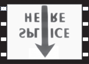
Consider shapes when you need a repeatable pattern of some type, as in Figure 3.15. Using the Repeater, you only have to adjust a single shape to edit all instances of it and how it is arrayed.
Figure 3.15. Shapes are not mere eye candy fodder, are they? The sprocket holes in this film were made with a Rounded Corner shape and a Repeater. (I even added an Inner Shadow Layer Style to give a little feeling of depth and dimension.)
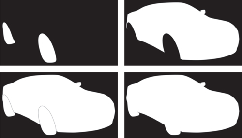
Combine Selections
By default, all masks are drawn in Add mode, meaning that the contents of the mask are added to the layer selection and the area outside all of the masks is excluded.
• The Add mode masks contents to the image as a whole (Figure 3.16).
Figure 3.16. Add mode combines the luminance values of overlapping masks.
• Subtract masks contents from displayed areas of the image (Figure 3.17).
Figure 3.17. Subtract mode is the inverse of Add mode.
• Intersect masks contents to show only areas overlapping with masks higher in the stack (Figure 3.18).
Figure 3.18. Intersect mode adds only the overlapping areas of opacity.
• Difference masks contents to hide areas overlapping with masks higher in the stack (Figure 3.19).
Figure 3.19. The inverse of Intersect, Difference mode subtracts overlapping areas.

• None disables the mask (Figure 3.20).
Figure 3.20. With None mode, the mask is effectively deactivated.

The Inverted toggle next to Add mode selects the areas outside the mask to be added; combined with Subtract it causes the areas outside the mask to be subtracted, and so on.
Tip
Preferences > User Interface Color > Cycle Mask Colors assigns a unique color to each new mask. Enable it.; it makes masking better and is disabled by default.
The Mask Opacity property (TT) attenuates the strength of a mask; setting any mask other than the first one to 0% disables it. This control works differently for the first (top) mask. A single Add mask set to 0% Mask Opacity causes the entire layer to disappear, inside or outside the mask.
However, if you set the first mask to Subtract, and Mask Opacity to 50%, it does just that—instead of the area inside the mask reappearing, the rest of the scene becomes 50% transparent. It’s the same result as Add > Inverted. It will behave as it should if you set another full-frame mask at the default Add mode (just double-click the rectangle mask), then add the Subtract mask as the second (or later).
To keep multiple masks organized
• enable Preferences > User Interface Color > Cycle Mask Colors to assign a unique color to each new mask
• press the Enter (Return) key with a mask selected, then type in a unique name
• click Mask Color swatch (to the left of the name) to make it more visible or unique
• context-click > Mask > Locked, Mask > Lock Other Masks, or Mask > Hide Locked Masks to keep masks you no longer wish to edit out of your way
Overlap Transparent Density
“Density” is a film term describing how dark (opaque or “dense”) the frame of film is at a given area of the image: the higher the density, the less light is transmitted. Masks and alpha channels are also referred to in terms of “density,” and when two masks or mattes overlap, density can build up when it should not (with masks) or fail to build up when it should (with mattes).
Notes
![]()
Chapter 7 demonstrates how effective rotoscoping involves multiple simple masks used in combination instead of one big complex mask.
Figures 3.21 and 3.22 show the simple solution to a common problem; the Darken and Lighten mask modes prevent any pixel from becoming more dense than it is in the semi-transparent areas of either matte. These modes should be applied to the masks that are below overlapping masks in the stack in order to work.
Figure 3.21. A Darken mask (left) uses only the darker (lower) value where threshold (semi-opaque) pixels overlap. It prevents two masks from building up density as in Intersect mode (right).

Figure 3.22. A Lighten mask (left) uses only the lighter (higher) value where threshold (semi-opaque) pixels overlap. It prevents two masks from building up density as in Add mode (right).
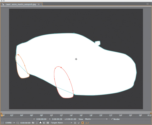
Overlap Inverted Layers Seamlessly
Suppose it’s necessary to break out a selection into segments and adjust each segment as a separate layer, then combine them in the final result. A gap will appear along the threshold areas of the matte for the reasons explained in the Opacity section earlier; two overlapping 50% opaque pixels do not make a 100% opaque combined pixel.
Just as the name implies, the Alpha Add blending mode directly adds transparent pixels, instead of scaling them proportionally (Figure 3.23). You can cut out a piece of a layer, feather the matte, and apply the inverted feathered matte to the rest of the layer. Recombine them with Alpha Add applied to the top layer, and the seam disappears.
Figure 3.23. Comp a layer with matte A (upper left) over one with matte B (upper right) and you get a halo along the overlapping, inverted threshold edge pixels—around the wheels (bottom left). Alpha Add does just what the title implies, adding the alpha values together directly (bottom right).
Animated Masks
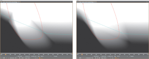
Following are some basics to put a mask in motion. Alt+M (Opt+M) sets a mask keyframe to all unlocked layer masks. Mask movement can be eased temporally, but there are no spatial curves; each mask point travels in a completely linear fashion from one keyframe to the next. An arced motion requires many more keyframes.
You can only adjust a mask point on one keyframe at a time, even if you select multiple Mask Path keyframes before adjusting. If you must arc or offset the motion of an entire mask animation, one workaround is to duplicate the masked layer and use it as an alpha track matte for the source layer, then keyframe the track matte like any animated layer.
Script
![]()
KeyTweak by Mathias Möhl (http://aescripts.com/keytweak/) achieves the seemingly impossible: Edit a keyframed mask globally simply by adjusting points on one or two mask keyframes, and the rest are automagically changed accordingly. It works not just for Mask Shape keys but for any keyframed property. This means it can be used, for example, to correct a drifting track.
Move, Copy, and Paste Masks
Copy a mask path from any compatible source, whether it’s
• a Mask Path property from a separate mask or layer
• a Mask Path keyframe from the same or a separate mask
• a mask path from a separate Adobe application such as Illustrator or Photoshop
and paste it into an existing Mask Path channel, or paste it to the layer to create a new mask. If there are any keyframes, they are pasted in as well, beginning at the current time; make sure they don’t conflict with existing keyframes in the mask shape.
Notes
![]()
If a pasted mask targets a layer with dimensions unique from the source, the mask stretches proportionally.
To draw an entirely new shape for an existing, keyframed mask path, use the Target menu along the bottom of the Layer panel to choose the existing mask as a target, and start drawing. This replaces the existing shape (Figure 3.24).
Figure 3.24. This pop-up menu along the bottom of the Layer panel makes it easy to create a new mask path that replaces the shape in the target mask. If the target mask has keyframes, After Effects creates a new keyframe wherever the new shape is drawn.

First Vertex
When pasting in shapes or radically changing the existing mask by adding and deleting points, you may run into difficulty lining up the points. Hidden away in the Layer > Mask (or Mask context) menu, and available only with a single vertex of the mask selected, is the Set First Vertex command.
If your mask points twist around to the wrong point during an interpolation, setting the First Vertex to two points that definitely correspond should help straighten things out. This also can be imperative for effects that rely on mask shapes, such as Reshape (described in Chapter 7).
Notes
![]()
Window > Mask Interpolation is designed to smooth transitions between radically different shapes.
Composite With or Without Selections: Blending Modes
After Effects includes 38 blending modes, each created with a specific purpose, but as with anything, for visual effects work the 80/20 rule is in full effect—a few of them, featured in this section, do most of the work, while Pin Light or Dancing Dissolve may be used only for motion graphics styling, if that. The goal is to help you understand how each option actually operates and in what situations it’s useful.
Script
![]()
ReverseMaskPath by Charles Bordenave (http://aescripts.com/reversemaskpath/) reverses the direction of selected masks without altering the shape, which is useful in any situation where point direction matters, including with effects that use open mask shapes such as Stroke and Trapcode 3D Stroke.
Close-up: Normalized Pixel Values
![]()
Most digital artists become used to color values in the 8 bpc range of 0 to 255, but the internal math of compositing is all done with pixel values normalized to 1. This means that a pure monitor white value of 255 is expressed as 1, and black is 0. Chapter 11 shows how values above 1 and below 0 are also possible; these operations also make much more sense when working with values normalized to 1, which is an optional mode in the After Effects Info panel—and all associated color controls—no matter the bit depth (Figure 3.25).
Figure 3.25. The panel menu for Info has more than one mode, and you can choose whichever you like. Whichever mode you select also carries over to the Adobe Color Picker and all other color controls within After Effects.

To help you understand what the various blending modes are doing, Figure 3.26 features text with a soft (large threshold) edge over a grayscale gradient, blended with a color gradient, while Figure 3.28 uses the same text over a single contrasting color. Contextual examples using these blending modes follow in the next section. (The 03_blend_mode_stills folder and project on the disc contain the examples shown.)
Notes
![]()
Traditional optical compositing—covering all movies made prior to the 1990s—was capable of bi-packing (multiplying) and double-exposing (adding) two source frames (layers). Many sophisticated effects films were completed using only these two “blending modes.”
Figure 3.26. Check out the example containing the word “normal” to see the basic elements: soft text in a grayscale box on the top layer that will have the blending mode, and a simple blue (primary) to yellow (secondary, in a digital additive color world) color gradient behind.
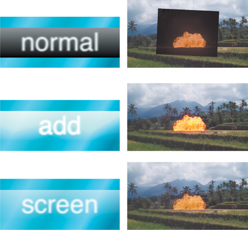
Add and Screen
Add and Screen modes both effectively brighten the lighter areas of the layer where they overlap with light areas of the image behind them. They also subdue darker pixels such that the blacks are not factored. Screen mode yields a subtler blend than Add mode in normal video color space, but Add is preferred with linear blending (details in Chapter 11).

An Add blending mode is every bit as simple as it sounds; the formula is
newPixel = A + B
where A is a pixel from the foreground layer and B is a background pixel. The result is clipped at 1 for 8- and 16-bit pixels.
Add is incredibly useful with what After Effects calls a linearized working space, where it perfectly re-creates the optical effect of combining light values from two images, as with a film double-exposure (if that analog reference has any resonance in this digital era). It is useful for laying fire and explosion elements shot in negative space (against black) into a scene, adding noise or grain to an element, or any other element that is made up of light and texture, as in Figure 3.26.
Screen mode yields a result similar to Add, but via a slightly different formula. The pixel values are inverted and multiplied together, and the result is inverted back in order to prevent clipping (pushing values above 1, which is the upper limit in 8 or 16 bpc):
newPixel = 1–((1–A) * (1–B))
Notes
![]()
In Screen mode, fully white pixels stay white, fully black pixels stay black, but a midrange pixel (0.5) takes on a brighter value (0.75), just not as bright as it would be with Add (1).
Once you discover the truth about working linearized with a 1.0 gamma, you understand that Screen is a workaround, a compromise for how colors blend in normal video space. Screen is most useful in situations where Add would blow out the highlights too much—glints, flares, glow passes, and so on; check out the subtle but clear difference in Figure 3.26.
Notes
![]()
The difference between Add and Screen is more fully illuminated in the discussion of a linearized working space in Chapter 11.
Multiply
Multiply is another mode whose math is as elementary as it sounds; it uses the formula
newPixel = A * B
Keep in mind that this formula normalizes color values between 0 and 1 (see the earlier sidebar “Normalized Pixel Values”). Multiplying two images together, therefore, typically has the effect of reducing midrange pixels and darkening an image overall, although pixels that are fully white in both images remain fully white, because 1 × 1 = 1.
Multiply or Add has the inverse effect of Screen mode, darkening the midrange values of one image with another. It emphasizes dark tones in the foreground without replacing the lighter tones in the background, useful for creating texture, shadow, or dark fog, as in Figure 3.26 (which features that type of foreground element generated with simple Fractal Noise—as you’ll see in Chapter 13—instead of fire).
Overlay and the Light Modes
Overlay uses the Screen or Multiply formula, depending on the background pixel value. Above a threshold of 50% gray (or .5 in normalized terms), a Screen operation is used, and below the threshold, Multiply is used. Hard Light does the exact same thing but bases the operation on the top layer, so the two have an inverse effect.
Notes
![]()
Overlay and the various Light modes do not work properly with values above 1.0, as can occur in 32 bpc linearized working spaces (see Chapter 11).
These modes, along with Linear and Vivid Light, can be most useful for combining a layer that is predominantly color with another layer that is predominantly luminance, or contrast detail, as in Figure 3.26. I can add the firsthand anecdote that much of the lava texturing in the Level 4 sequence of Spy Kids 3-D was created by using Hard Light to combine a hand-painted color heat map with moving fractal noise patterns (for that videogame look).
Difference
Difference inverts a background pixel in proportion to the foreground pixel. I don’t use it as much in my actual comps as I do to line up two identical layers (Figure 3.27).
Figure 3.27. This layer is Difference matted over itself—in this image it is offset just slightly, creating contrasting outlines where the edges don’t match up. When two layers with identical image content become completely black in Difference mode, you know they are perfectly aligned.

HSB and Color Modes
The Hue, Saturation, and Brightness modes each combine one of these values (H, S, or B) from the foreground layer with the other two from the background layer. Color takes both the hue and saturation from the top layer, using only the luminance (or brightness) from the underlying background (Figure 3.28).
These modes are often useful at an Opacity setting below 100% to combine source HSB values with ones that you choose.
Figure 3.28. Color modes are not intuitive at first, but once you see what they do, you are likely to find uses for them.

Stencil, Silhouette, and Preserve Transparency
Commonly overlooked, Stencil and Silhouette blending modes operate only on the alpha channel of the composition. The layer’s alpha or luminance values become a matte for all layers below it in the stack. Stencil makes the brightest pixels opaque, and Silhouette the darkest.
Notes
![]()
Stencil Alpha and Silhouette Alpha are useful to create custom edge mattes (a technique detailed in Chapter 6) as well as a light wrap effect, demonstrated in Chapter 12.
Suppose you have a foreground layer that is meant to be opaque only where the underlying layers are opaque, as in Figure 3.29. The small highlighted toggle labeled Preserve Underlying Transparency makes this happen, much to the amazement of many who’ve wished for this feature and not realized it was already there.
Figure 3.29. Among the hardest-to-find and most-easily-forgotten features in the Timeline is the Preserve Underlying Transparency toggle, circled. This re-creates behavior familiar to Photoshop users, where a layer’s own transparency only applies where it intersects with that of the underlying layer. Here the same gradient is simply placed over a text layer; without this mode, the gradient would fill the frame as a solid.

Luminescent Premultiply
Luminescent Premultiply is one method you can use to remove premultiplication on the fly from source footage, retaining bright values in edge pixels that are otherwise clipped. Premultiplication over black causes all semitransparent pixels to become darker; removing it can cause them to appear dimmer than they should.
Luminescent Premultiply is used to remove premultiplication (for cases in which edges have somehow become multiplied within After Effects). In Figure 3.30, the source text over black has been matted using the same layer—white text over black—as a luma matte, which means that black remains multiplied into the background unless this mode is set.
Figure 3.30. Did you create edge multiplication by luma matting a layer against black with itself (left)? Luminescent Premultiply (right) fixes this.

Track Mattes
Track mattes allow you to use the alpha or luminance information of one layer as the transparency of another layer (Figure 3.31). It’s a simple enough concept, yet one that is absolutely fundamental as a problem-solving tool for complex composites.
Close-up: Adjustment Layers and Blending Modes
![]()
Here’s something I didn’t used to know, and you may not either—when you apply a blending mode to an Adjustment layer, that layer’s effects are first applied and then the result is comped over the underlying layers with that mode applied. In other words, if you create an Adjustment layer with a Levels effect in Add mode, the Levels effect is applied to underlying layers and that result is then added to them. Leave Levels at the default in this scenario and the area defined by the Adjustment layer—usually the entire underlying image—is added to itself.
The perceptual difference between an alpha channel and a track matte isn’t, for the most part, too difficult to grasp. In both cases, you have pixels with an 8-bit value between 0 and 255, whether derived from a grayscale alpha matte or the grayscale average of three channels of color, a luma matte. With color, the three channels are simply averaged together to make up a single grayscale alpha. With 16 and even 32 bpc, it’s finer increments in the same range.
Figure 3.31. The alpha of layer 1 is set as the alpha of layer 2 via the circled pop-up menu. The small icons to the left indicate which is the image and which is the matte.

To set a track matte, place the layer that contains the transparency data directly above its target layer in the Timeline and choose one of the four options from the Track Matte pop-up menu:
• Alpha Matte: The alpha channel of the track matte layer is the alpha
• Alpha Inverted Matte: Same but the black areas are opaque
• Luma Matte: Uses the average brightness of red, green, and blue as the alpha
• Luma Inverted Matte: Same but the black areas are opaque
By default, the visibility of the track matte layer is disabled when you activate it from the layer below by choosing one of these four modes. This is generally desirable. Some clever uses of track mattes leave them on. For example, by matting out the bright areas of the image and turning on the matte, and setting it to Add mode, you could naturally brighten those areas even more.
Track mattes solve a lot of compositing problems. They also help overcome limitations of After Effects. Chapter 7 describes more uses for them.
Gotchas
Even an advanced user has to pay attention when working in a composition with track mattes. Unlike parented layers, track mattes do not stay connected with their target if moved around; they must occupy the layer directly above in order to work.
Close-up: Share a Matte
![]()
Node-based compositing programs make it easy for a single node to act as a selection for as many others as needed without being duplicated. The way to do this in After Effects is using the Set Matte effect, detailed below, which has the disadvantage of having no visible reference in the Timeline or Flowchart views. The standard way in After Effects to provide one-to-many operation is to precomp the matte being shared and then duplicate the nested comp layer as needed, but this complicates dynamic adjustments such as animating the matte layer in the master composition.
After Effects does help manage changes in certain ways. Duplicate a layer (Ctrl+D/Cmd+D) with a track matte activated and it moves up two layers, above the track matte layer. Include the track matte when you duplicate and it also moves up two layers, so layer order is preserved (Figure 3.32).
Figure 3.32. Select and duplicate two layers that are paired to make use of a track matte (as in Figure 3.31), and the two duplicate layers leapfrog above to maintain the proper image and matte relationship.

There is a workaround that allows a matte layer to be anywhere in the Timeline, but it offers its own perils. Effect > Channel > Set Matte not only lets you choose any layer in the comp as a matte, it keeps track if that layer moves to a different position. It also offers a few custom matte-handling options regarding how the matte is scaled and combined. However, nothing you add to the other layer, including Transform keyframes, is passed through; these would need to be added in a precomp.
Chapter 9 focuses on 3D compositing; for now, keep in mind that while you might want to use a 2D layer as a track matte for a 3D layer, or even a 3D layer to matte a 2D layer, rarely will you want to matte a 3D layer with another 3D layer. The reason is that the matte is applied to the underlying layer and then any animation is added to both layers—so it becomes a double 3D animation (or possibly a glimpse into the ninth dimension, we can’t be sure—either way it doesn’t usually look right).
Notes
![]()
Combine a track matte and an image with an alpha channel, and the selection uses an intersection of the two.
This brings us to render order with track mattes. In most cases, adjustments and effects that you apply to the matte layer are calculated prior to creating the target matte. To see how this can break, however, try applying a track matte to another track matte. It works... sometimes, but not often enough that it should become something you try unless you’re willing to troubleshoot it.
Notes
![]()
If you’re not certain whether your edits to the matte are being passed through, save the project and try cranking them up so it’s obvious. Then undo or revert. If it’s not working, precomp the matte layer.
Right Tool for the Job
The goal of this chapter is to give you a comprehensive look at your options for creating a selection in After Effects and some hints as to where you might ideally use each of them. In many cases you have more than one viable option to create a given composite, and this is where you must learn to look a little bit into the future. Which approach offers the most flexibility and overall control given what may evolve or be changed or even deleted? Which can be done with the fewest steps? Which is most lucid and easily understandable to anyone else who might work with your project?
Now that we’ve covered selections in some detail, the next chapter looks in depth at solving specific workflow issues, including those that pertain to render order; you’ll begin to see how to use the Timeline as a visual problem-solving tool for such situations.