Chapter 2. Network Design Models
This chapter covers the following subjects:
Cisco Enterprise Architecture Model
High Availability Network Services
This chapter reviews the hierarchical network model and introduces Cisco’s Enterprise Architecture model. This architecture model separates network design into more manageable modules. This chapter also addresses the use of device, media, and route redundancy to improve network availability.
“Do I Know This Already?” Quiz
The “Do I Know This Already?” quiz helps you identify your strengths and deficiencies in this chapter’s topics.
The eight-question quiz, derived from the major sections in the “Foundation Topics” portion of the chapter, helps you determine how to spend your limited study time.
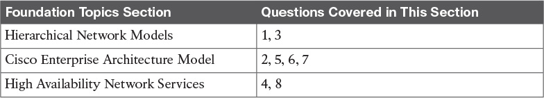
Table 2-1 outlines the major topics discussed in this chapter and the “Do I Know This Already?” quiz questions that correspond to those topics.
1. In the hierarchical network model, which layer is responsible for fast transport?
a. Network layer
b. Core layer
c. Distribution layer
d. Access layer
2. Which Enterprise Architecture model component interfaces with the service provider (SP)?
a. Campus infrastructure
b. Access layer
c. Enterprise edge
d. Edge distribution
3. In the hierarchical network model, at which layer do security filtering, address aggregation, and media translation occur?
a. Network layer
b. Core layer
c. Distribution layer
d. Access layer
4. Which of the following is (are) a method (methods) of workstation-to-router redundancy in the access layer?
a. AppleTalk Address Resolution Protocol (AARP)
b. Hot Standby Router Protocol (HSRP)
c. Virtual Router Redundancy Protocol (VRRP)
d. Answers b and c
e. Answers a, b, and c
5. The network-management module has tie-ins to which component(s)?
a. Campus infrastructure
b. Server farm
c. Enterprise edge
d. SP edge
e. Answers a and b
f. Answers a, b, and c
g. Answers a, b, c, and d
6. Which of the following is an SP edge module in the Cisco Enterprise Architecture model?
a. Public switched telephone network (PSTN) service
b. Edge distribution
c. Server farm
d. Core layer
7. In which module would you place Cisco Unified Communications Manager (CUCM)?
a. Campus core
b. E-commerce
c. Server farm
d. Edge distribution farm
8. High availability, port security, and rate limiting are functions of which hierarchical layer?
a. Network layer
b. Core layer
c. Distribution layer
d. Access layer
Foundation Topics
With the complexities of network design, the CCDA needs to understand network models used to simplify the design process. The hierarchical network model was one of the first Cisco models that divided the network into core, distribution, and access layers.
The Cisco Enterprise Architecture model provides a functional modular approach to network design. In addition to a hierarchy, modules are used to organize server farms, network management, campus networks, WANs, and the Internet. A modular approach to network design allows for higher scalability, better resiliency, and easier fault isolation of the network.
Hierarchical Network Models

Hierarchical models enable you to design internetworks that use specialization of function combined with a hierarchical organization. Such a design simplifies the tasks required to build a network that meets current requirements and can grow to meet future requirements. Hierarchical models use layers to simplify the tasks for internetworking. Each layer can focus on specific functions, allowing you to choose the right systems and features for each layer. Hierarchical models apply to both LAN and WAN design.
Benefits of the Hierarchical Model
The benefits of using hierarchical models for your network design include the following:
![]() Cost savings
Cost savings
![]() Ease of understanding
Ease of understanding
![]() Modular network growth
Modular network growth
![]() Improved fault isolation
Improved fault isolation
After adopting hierarchical design models, many organizations report cost savings because they are no longer trying to do everything in one routing or switching platform. The model’s modular nature enables appropriate use of bandwidth within each layer of the hierarchy, reducing the provisioning of bandwidth in advance of actual need.
Keeping each design element simple and functionally focused facilitates ease of understanding, which helps control training and staff costs. You can distribute network monitoring and management reporting systems to the different layers of modular network architectures, which also helps control management costs.
Hierarchical design facilitates changes and growth. In a network design, modularity lets you create design elements that you can replicate as the network grows—allowing maximum scalability. As each element in the network design requires change, the cost and complexity of making the upgrade are contained to a small subset of the overall network. In large, flat network architectures, changes tend to impact a large number of systems. Limited mesh topologies within a layer or component, such as the campus core or backbone connecting central sites, retain value even in the hierarchical design models.
Structuring the network into small, easy-to-understand elements improves fault isolation. Network managers can easily understand the transition points in the network, which helps identify failure points. It is more difficult to troubleshoot if hierarchical design is not used because the network is not divided into segments.
Today’s fast-converging protocols were designed for hierarchical topologies. To control the impact of routing-protocol processing and bandwidth consumption, you must use modular hierarchical topologies with protocols designed with these controls in mind, such as the Open Shortest Path First (OSPF) routing protocol.
Hierarchical network design facilitates route summarization. Enhanced Interior Gateway Routing Protocol (EIGRP) and all other routing protocols benefit greatly from route summarization. Route summarization reduces routing-protocol overhead on links in the network and reduces routing-protocol processing within the routers. It is less possible to provide route summarization if the network is not hierarchical.
Hierarchical Network Design
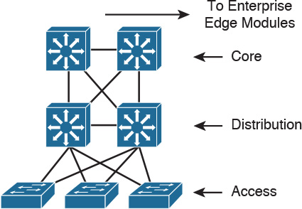
As shown in Figure 2-1, a traditional hierarchical LAN design has three layers:
![]() The core layer provides fast transport between distribution switches within the enterprise campus.
The core layer provides fast transport between distribution switches within the enterprise campus.
![]() The distribution layer provides policy-based connectivity.
The distribution layer provides policy-based connectivity.
![]() The access layer provides workgroup and user access to the network.
The access layer provides workgroup and user access to the network.
Each layer provides necessary functionality to the enterprise campus network. You do not need to implement the layers as distinct physical entities. You can implement each layer in one or more devices or as cooperating interface components sharing a common chassis. Smaller networks can “collapse” multiple layers to a single device with only an implied hierarchy. Maintaining an explicit awareness of hierarchy is useful as the network grows.
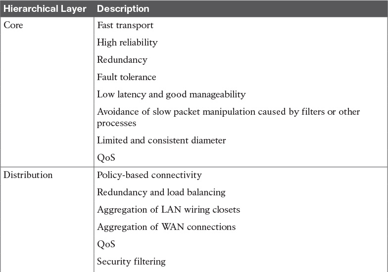
Core Layer
The core layer is the network’s high-speed switching backbone that is crucial to corporate communications. It is also referred as the backbone. The core layer should have the following characteristics:
![]() High reliability
High reliability
![]() Redundancy
Redundancy
![]() Fault tolerance
Fault tolerance
![]() Low latency and good manageability
Low latency and good manageability
![]() Avoidance of CPU-intensive packet manipulation caused by security, inspection, quality of service (QoS) classification, or other processes
Avoidance of CPU-intensive packet manipulation caused by security, inspection, quality of service (QoS) classification, or other processes
![]() Limited and consistent diameter
Limited and consistent diameter
![]() QoS
QoS
When a network uses routers, the number of router hops from edge to edge is called the diameter. As noted, it is considered good practice to design for a consistent diameter within a hierarchical network. The trip from any end station to another end station across the backbone should have the same number of hops. The distance from any end station to a server on the backbone should also be consistent.
Limiting the internetwork’s diameter provides predictable performance and ease of troubleshooting. You can add distribution layer routers and client LANs to the hierarchical model without increasing the core layer’s diameter. Use of a block implementation isolates existing end stations from most effects of network growth.
Distribution Layer
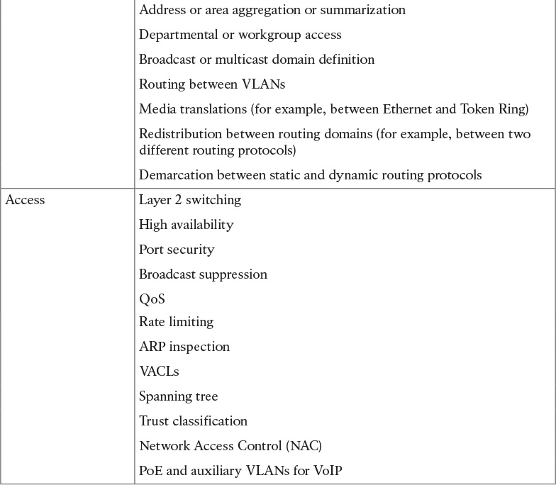
The network’s distribution layer is the isolation point between the network’s access and core layers. The distribution layer can have many roles, including implementing the following functions:
![]() Policy-based connectivity (for example, ensuring that traffic sent from a particular network is forwarded out one interface while all other traffic is forwarded out another interface)
Policy-based connectivity (for example, ensuring that traffic sent from a particular network is forwarded out one interface while all other traffic is forwarded out another interface)
![]() Redundancy and load balancing
Redundancy and load balancing
![]() Aggregation of LAN wiring closets
Aggregation of LAN wiring closets
![]() Aggregation of WAN connections
Aggregation of WAN connections
![]() QoS
QoS
![]() Security filtering
Security filtering
![]() Address or area aggregation or summarization
Address or area aggregation or summarization
![]() Departmental or workgroup access
Departmental or workgroup access
![]() Broadcast or multicast domain definition
Broadcast or multicast domain definition
![]() Routing between virtual LANs (VLANs)
Routing between virtual LANs (VLANs)
![]() Media translations (for example, between Ethernet and Token Ring)
Media translations (for example, between Ethernet and Token Ring)
![]() Redistribution between routing domains (for example, between two different routing protocols)
Redistribution between routing domains (for example, between two different routing protocols)
![]() Demarcation between static and dynamic routing protocols
Demarcation between static and dynamic routing protocols
You can use several Cisco IOS Software features to implement policy at the distribution layer:
![]() Filtering by source or destination address
Filtering by source or destination address
![]() Filtering on input or output ports
Filtering on input or output ports
![]() Hiding internal network numbers by route filtering
Hiding internal network numbers by route filtering
![]() Static routing
Static routing
![]() QoS mechanisms, such as priority-based queuing
QoS mechanisms, such as priority-based queuing
The distribution layer provides aggregation of routes providing route summarization to the core. In the campus LANs, the distribution layer provides routing between VLANs that also apply security and QoS policies.
Access Layer
The access layer provides user access to local segments on the network. The access layer is characterized by switched LAN segments in a campus environment. Microsegmentation using LAN switches provides high bandwidth to workgroups by reducing the number of devices on Ethernet segments. Functions of the access layer include the following:
![]() Layer 2 switching
Layer 2 switching
![]() High availability
High availability
![]() Port security
Port security
![]() Broadcast suppression
Broadcast suppression
![]() QoS classification and marking and trust boundaries
QoS classification and marking and trust boundaries
![]() Rate limiting/policing
Rate limiting/policing
![]() Address Resolution Protocol (ARP) inspection
Address Resolution Protocol (ARP) inspection
![]() Virtual access control lists (VACLs)
Virtual access control lists (VACLs)
![]() Spanning tree
Spanning tree
![]() Trust classification
Trust classification
![]() Power over Ethernet (PoE) and auxiliary VLANs for VoIP
Power over Ethernet (PoE) and auxiliary VLANs for VoIP
![]() Auxiliary VLANs
Auxiliary VLANs
You implement high availability models at the access layer. The section “High Availability Network Services” covers availability models. The LAN switch in the access layer can control access to the port and limit the rate at which traffic is sent to and from the port. You can implement access by identifying the MAC address using ARP, trusting the host, and using access lists.
Other chapters of this book cover the other functions in the list.
For small office/home office (SOHO) environments, the entire hierarchy collapses to interfaces on a single device. Remote access to the central corporate network is through traditional WAN technologies such as ISDN, Frame Relay, and leased lines. You can implement features such as dial-on-demand routing (DDR) and static routing to control costs. Remote access can include virtual private network (VPN) technology.
Table 2-2 summarizes the hierarchical layers.
Hierarchical Model Examples
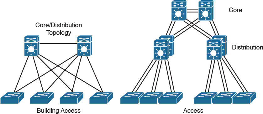
You can implement the hierarchical model by using a traditional switched campus design or routed campus network. Figure 2-2 is an example of a switched hierarchical design in the enterprise campus. In this design, the core provides high-speed transport between the distribution layers. The building distribution layer provides redundancy and allows policies to be applied to the building access layer. Layer 3 links between the core and distribution switches are recommended to allow the routing protocol to take care of load balancing and fast route redundancy in the event of a link failure. The distribution layer is the boundary between the Layer 2 domains and the Layer 3 routed network. Inter-VLAN communications are routed in the distribution layer. Route summarization is configured under the routing protocol on interfaces towards the core layer. The drawback with this design is that Spanning Tree Protocol (STP) allows only one of the redundant links between the access switch and the distribution switch to be active. In the event of a failure, the second link becomes active, but at no point does load balancing occur.
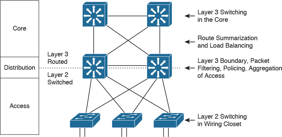
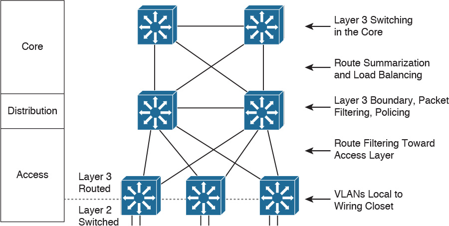
Figure 2-3 shows examples of a routed hierarchical design. In this design, the Layer 3 boundary is pushed toward the access layer. Layer 3 switching occurs in access, distribution, and core layers. Route filtering is configured on interfaces toward the access layer. Route summarization is configured on interfaces toward the core layer. The benefit of this design is that load balancing occurs from the access layer since the links to the distribution switches are routed.
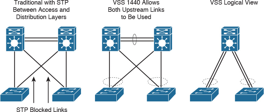
Another solution for providing redundancy between the access and distribution switching is the Virtual Switching System (VSS). VSS solves the STP looping problem by converting the distribution switching pair into a logical single switch. It removes STP and negates the need for Hot Standby Router Protocol (HSRP), Virtual Router Redundancy Protocol (VRRP), or Gateway Load Balancing Protocol (GLBP).
With VSS, the physical topology changes as each access switch has a single upstream distribution switch versus having two upstream distribution switches. VSS is configured only on Cisco 6500 switches using the VSS Supervisor 720-10G. As shown in Figure 2-4, the two switches are connected via 10GE links called virtual switch links (VSLs), which makes them seem as a single switch. The key benefits of VSS include the following:
![]() Layer 3 switching can be used toward the access layer, enhancing nonstop communication.
Layer 3 switching can be used toward the access layer, enhancing nonstop communication.
![]() Scales system bandwidth up to 1.44 Tbps.
Scales system bandwidth up to 1.44 Tbps.
![]() Simplified management of a single configuration of the VSS distribution switch.
Simplified management of a single configuration of the VSS distribution switch.
![]() Better return on investment (ROI) via increased bandwidth between the access layer and the distribution layer.
Better return on investment (ROI) via increased bandwidth between the access layer and the distribution layer.
![]() Supported on Catalyst 4500, 6500, and 6800 switches.
Supported on Catalyst 4500, 6500, and 6800 switches.
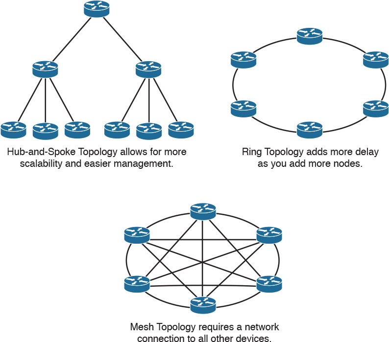
Hub-and-Spoke Design
For designing networks, the hub-and-spoke design provides better convergence times than ring topology. The hub-and-spoke design, illustrated in Figure 2-5, also scales better and is easier to manage than ring or mesh topologies. For example, implementing security policies in a full mesh topology would become unmanageable because you would have to configure policies at each point location.
Collapsed Core Design
One alternative to the three-layer hierarchy is the collapsed core design. It is a two-layer hierarchy used with smaller networks. It is commonly used on sites with a single building with just multiple floors. As shown in Figure 2-6, the core and distribution layers are merged, providing all the services needed for those layers. Design parameters to decide if you need to migrate to the three-layer hierarchy include not enough capacity and throughput at the distribution layer, network resiliency, and geographic dispersion.
Cisco Enterprise Architecture Model
The Cisco Enterprise Architecture model facilitates the design of larger, more scalable networks.
As networks become more sophisticated, it is necessary to use a more modular approach to design than just WAN and LAN core, distribution, and access layers. The architecture divides the network into functional network areas and modules. These areas and modules of the Cisco Enterprise Architecture are
![]() Enterprise campus area
Enterprise campus area
![]() Enterprise branch module
Enterprise branch module
The Cisco Enterprise Architecture model maintains the concept of distribution and access components connecting users, WAN services, and server farms through a high-speed campus backbone. The modular approach in design should be a guide to the network architect. In smaller networks, the layers can collapse into a single layer, even a single device, but the functions remain.
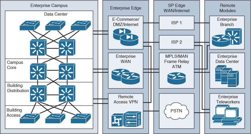
Figure 2-7 shows the Cisco Enterprise Architecture model. The enterprise campus area contains a campus infrastructure that consists of core, building distribution, and building access layers, with a data center module. The enterprise edge area consists of the Internet, e-commerce, VPN, and WAN modules that connect the enterprise to the service provider’s facilities. The SP edge area provides Internet, public switched telephone network (PSTN), and WAN services to the enterprise.
The network management servers reside in the campus infrastructure but have tie-ins to all the components in the enterprise network for monitoring and management.
The enterprise edge connects to the edge-distribution module of the enterprise campus. In small and medium sites, the edge distribution can collapse into the campus backbone component. It provides connectivity to outbound services that are further described in later sections.
Enterprise Campus Module
The enterprise campus consists of the following submodules:
![]() Campus core
Campus core
![]() Building distribution and aggregation switches
Building distribution and aggregation switches
![]() Building access
Building access
![]() Server farm/data center
Server farm/data center
Figure 2-8 shows the Enterprise Campus model. The campus infrastructure consists of the campus core, building distribution, and building access layers. The campus core provides a high-speed switched backbone between buildings, to the server farm, and towards the enterprise edge. This segment consists of redundant and fast-convergence connectivity. The building distribution layer aggregates all the closet access switches and performs access control, QoS, route redundancy, and load balancing. The building access switches provide VLAN access, PoE for IP phones and wireless access points, broadcast suppression, and spanning tree.
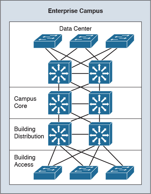
The server farm or data center provides high-speed access and high availability (redundancy) to the servers. Enterprise servers such as file and print servers, application servers, email servers, Dynamic Host Configuration Protocol (DHCP) servers, and Domain Name System (DNS) servers are placed in the server farm. Cisco Unified CallManager servers are placed in the server farm for IP telephony networks. Network management servers are located in the server farm, but these servers link to each module in the campus to provide network monitoring, logging, trending, and configuration management.
An enterprise campus infrastructure can apply to small, medium, and large locations. In most instances, large campus locations have a three-tier design with a wiring-closet component (building access layer), a building distribution layer, and a campus core layer. Small campus locations likely have a two-tier design with a wiring-closet component (Ethernet access layer) and a backbone core (collapsed core and distribution layers). It is also possible to configure distribution functions in a multilayer building access device to maintain the focus of the campus backbone on fast transport. Medium-sized campus network designs sometimes use a three-tier implementation or a two-tier implementation, depending on the number of ports, service requirements, manageability, performance, and availability required.
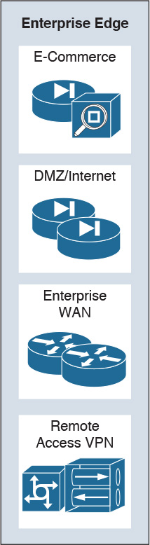
Enterprise Edge Area
As shown in Figure 2-9, the enterprise edge consists of the following submodules:
![]() Business web applications and databases, e-commerce networks and servers
Business web applications and databases, e-commerce networks and servers
![]() Internet connectivity and demilitarized zone (DMZ)
Internet connectivity and demilitarized zone (DMZ)
![]() VPN and remote access
VPN and remote access
![]() Enterprise WAN connectivity
Enterprise WAN connectivity
E-Commerce Module
The e-commerce submodule of the enterprise edge provides highly available networks for business services. It uses the high availability designs of the server farm module with the Internet connectivity of the Internet module. Design techniques are the same as those described for these modules. Devices located in the e-commerce submodule include the following:
![]() Web and application servers: Primary user interface for e-commerce navigation
Web and application servers: Primary user interface for e-commerce navigation
![]() Database servers: Contain the application and transaction information
Database servers: Contain the application and transaction information
![]() Firewall and firewall routers: Govern the communication between users of the system
Firewall and firewall routers: Govern the communication between users of the system
![]() Network intrusion prevention systems (IPS): Provide monitoring of key network segments in the module to detect and respond to attacks against the network
Network intrusion prevention systems (IPS): Provide monitoring of key network segments in the module to detect and respond to attacks against the network
![]() Multilayer switch with IPS modules: Provide traffic transport and integrated security monitoring
Multilayer switch with IPS modules: Provide traffic transport and integrated security monitoring
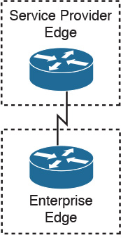
Internet Connectivity Module
The Internet submodule of the enterprise edge provides services such as public servers, email, and DNS. Connectivity to one or several Internet service providers (ISPs) is also provided. Components of this submodule include the following:
![]() Firewall and firewall routers: Provide protection of resources, stateful filtering of traffic, and VPN termination for remote sites and users
Firewall and firewall routers: Provide protection of resources, stateful filtering of traffic, and VPN termination for remote sites and users
![]() Internet edge routers: Provide basic filtering and multilayer connectivity
Internet edge routers: Provide basic filtering and multilayer connectivity
![]() FTP and HTTP servers: Provide for web applications that interface the enterprise with the world via the public Internet
FTP and HTTP servers: Provide for web applications that interface the enterprise with the world via the public Internet
![]() SMTP relay servers: Act as relays between the Internet and the intranet mail servers
SMTP relay servers: Act as relays between the Internet and the intranet mail servers
![]() DNS servers: Serve as authoritative external DNS servers for the enterprise and relay internal requests to the Internet
DNS servers: Serve as authoritative external DNS servers for the enterprise and relay internal requests to the Internet
Several models connect the enterprise to the Internet. The simplest form is to have a single circuit between the enterprise and the SP, as shown in Figure 2-10. The drawback is that you have no redundancy or failover if the circuit fails.
You can use multihoming solutions to provide redundancy or failover for Internet service. Figure 2-11 shows four Internet multihoming options:
![]() Option 1: Single router, dual links to one ISP
Option 1: Single router, dual links to one ISP
![]() Option 2: Single router, dual links to two ISPs
Option 2: Single router, dual links to two ISPs
![]() Option 3: Dual routers, dual links to one ISP
Option 3: Dual routers, dual links to one ISP
![]() Option 4: Dual routers, dual links to two ISPs
Option 4: Dual routers, dual links to two ISPs
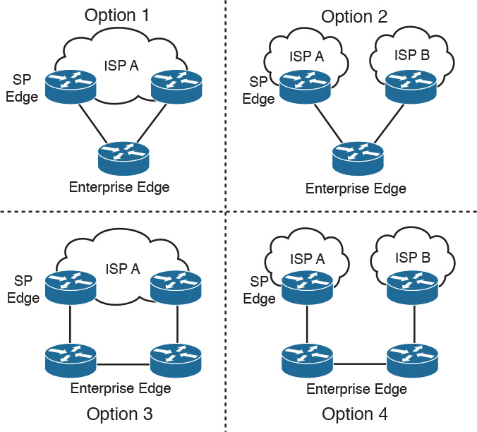
Option 1 provides link redundancy but does not provide ISP and local router redundancy. Option 2 provides link and ISP redundancy but does not provide redundancy for a local router failure. Option 3 provides link and local router redundancy but does not provide for an ISP failure. Option 4 provides for full redundancy of the local router, links, and ISPs.
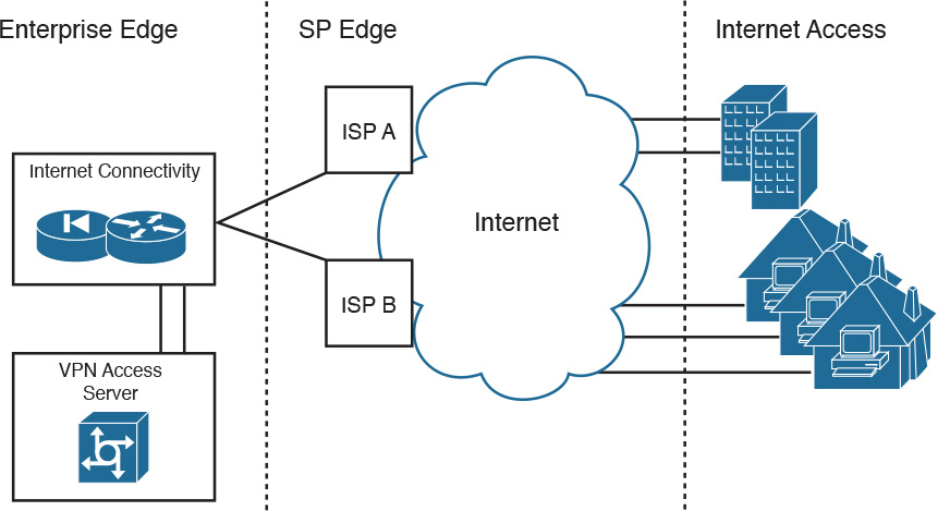
VPN/Remote Access
The VPN/remote access module of the enterprise edge provides remote-access termination services, including authentication for remote users and sites. Components of this submodule include the following:
![]() Firewalls: Provide stateful filtering of traffic, authenticate trusted remote sites, and provide connectivity using IPsec tunnels
Firewalls: Provide stateful filtering of traffic, authenticate trusted remote sites, and provide connectivity using IPsec tunnels
![]() Dial-in access concentrators: Terminate legacy dial-in connections and authenticate individual users
Dial-in access concentrators: Terminate legacy dial-in connections and authenticate individual users
![]() Cisco Adaptive Security Appliances (ASAs): Terminate IPsec tunnels, authenticate individual remote users, and provide firewall and intrusion prevention services
Cisco Adaptive Security Appliances (ASAs): Terminate IPsec tunnels, authenticate individual remote users, and provide firewall and intrusion prevention services
![]() Network intrusion prevention system (IPS) appliances
Network intrusion prevention system (IPS) appliances
If you use a remote-access terminal server, this module connects to the PSTN. Today’s networks often prefer VPNs over remote-access terminal servers and dedicated WAN links. VPNs reduce communication expenses by leveraging the infrastructure of SPs. For critical applications, the cost savings might be offset by a reduction in enterprise control and the loss of deterministic service. Remote offices, mobile users, and home offices access the Internet using the local SP with secured IPsec tunnels to the VPN/remote access submodule via the Internet submodule.
Figure 2-12 shows a VPN design. Branch offices obtain local Internet access from an ISP. Teleworkers also obtain local Internet access. VPN software creates secured VPN tunnels to the VPN server that is located in the VPN submodule of the enterprise edge.
Enterprise WAN
The enterprise edge of the enterprise WAN includes access to WANs. WAN technologies include the following:
![]() Multiprotocol Label Switching (MPLS)
Multiprotocol Label Switching (MPLS)
![]() Metro Ethernet
Metro Ethernet
![]() Leased lines
Leased lines
![]() Synchronous Optical Network (SONET) and Synchronous Digital Hierarchy (SDH)
Synchronous Optical Network (SONET) and Synchronous Digital Hierarchy (SDH)
![]() PPP
PPP
![]() Frame Relay
Frame Relay
![]() ATM
ATM
![]() Cable
Cable
![]() Digital subscriber line (DSL)
Digital subscriber line (DSL)
![]() Wireless
Wireless
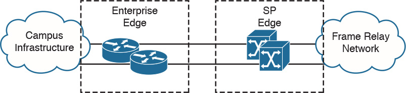
Chapter 6, “WAN Technologies and the Enterprise Edge,” and Chapter 7, “WAN Design,” cover these WAN technologies. Routers in the enterprise WAN provide WAN access, QoS, routing, redundancy, and access control to the WAN. Of these WAN technologies, MPLS is the most popular WAN technology used today. For MPLS networks, the WAN routers prioritize IP packets based on configured differentiated services code point (DSCP) values to use one of several MPLS QoS levels. Figure 2-13 shows the WAN module connecting to the Frame Relay SP edge. The enterprise edge routers in the WAN module connect to the SP’s Frame Relay switches.
Use the following guidelines when designing the enterprise edge:
![]() Determine the connection needed to connect the corporate network to the Internet. These connections are assigned to the Internet connectivity module.
Determine the connection needed to connect the corporate network to the Internet. These connections are assigned to the Internet connectivity module.
![]() Create the e-commerce module for customers and partners that require Internet access to business and database applications.
Create the e-commerce module for customers and partners that require Internet access to business and database applications.
![]() Design the remote access/VPN module for VPN access to the internal network from the Internet. Implement the security policy and configure authentication and authorization parameters.
Design the remote access/VPN module for VPN access to the internal network from the Internet. Implement the security policy and configure authentication and authorization parameters.
![]() Assign the edge sections that have permanent connections to remote branch offices. Assign these to the WAN, metro area network (MAN), and VPN module.
Assign the edge sections that have permanent connections to remote branch offices. Assign these to the WAN, metro area network (MAN), and VPN module.
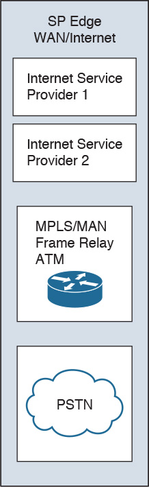
Service Provider Edge Module
The SP edge module, shown in Figure 2-14, consists of SP edge services such as the following:
![]() Internet services
Internet services
![]() PSTN services
PSTN services
![]() WAN services
WAN services
Enterprises use SPs to acquire network services. ISPs offer enterprises access to the Internet. ISPs can route the enterprise’s networks to their network and to upstream and peer Internet providers. ISPs can provide Internet services via Ethernet, DSL, or T1/DS3 access. It is common now for the SP to have their ISP router at the customer site and provide Ethernet access to the customer. Connectivity with multiple ISPs was described in the section “Internet Connectivity Module.”
For voice services, PSTN providers offer access to the global public voice network. For the enterprise network, the PSTN lets dialup users access the enterprise via analog or cellular wireless technologies. It is also used for WAN backup using ISDN services.
WAN SPs offer MPLS, Frame Relay, ATM, and other WAN services for enterprise site-to-site connectivity with permanent connections. These and other WAN technologies are described in Chapter 6.
Remote Modules
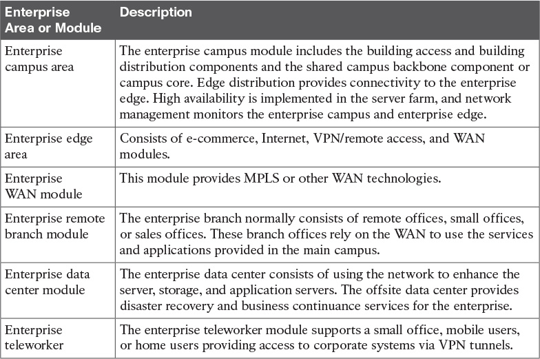
The remote modules of the Cisco Enterprise Architecture model are the enterprise branch, enterprise data center, and enterprise teleworker modules.
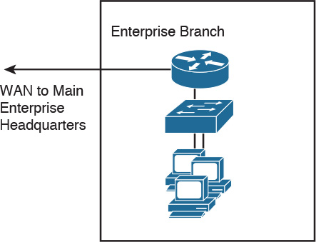
Enterprise Branch Module
The enterprise branch normally consists of remote offices or sales offices. These branch offices rely on the WAN to use the services and applications provided in the main campus. Infrastructure at the remote site usually consists of a WAN router and a small LAN switch, as shown in Figure 2-15. As an alternative to MPLS, it is common to use site-to-site IPsec VPN technologies to connect to the main campus.
Enterprise Data Center Module
The enterprise data center uses the network to enhance the server, storage, and application servers. The offsite data center provides disaster recovery and business continuance services for the enterprise. Highly available WAN services are used to connect the enterprise campus to the remote enterprise data center. The data center components include the following:
![]() Network infrastructure: Gigabit and 10 Gigabit Ethernet, InfiniBand, optical transport, and storage switching
Network infrastructure: Gigabit and 10 Gigabit Ethernet, InfiniBand, optical transport, and storage switching
![]() Interactive services: Computer infrastructure services, storage services, security, and application optimization
Interactive services: Computer infrastructure services, storage services, security, and application optimization
![]() DC management: Cisco Fabric Manager and Cisco VFrame for server and service management
DC management: Cisco Fabric Manager and Cisco VFrame for server and service management
The enterprise data center is covered in detail in Chapter 4, “Data Center Design.”
Enterprise Teleworker Module
The enterprise teleworker module consists of a small office or a mobile user who needs to access services of the enterprise campus. As shown in Figure 2-16, mobile users connect from their homes, hotels, or other locations using dialup or Internet access lines. VPN clients are used to allow mobile users to securely access enterprise applications. The Cisco Virtual Office solution provides a solution for teleworkers that is centrally managed using small integrated service routers (ISRs) in the VPN solution. IP phone capabilities are also provided in the Cisco Virtual Office solution, providing corporate voice services for mobile users.
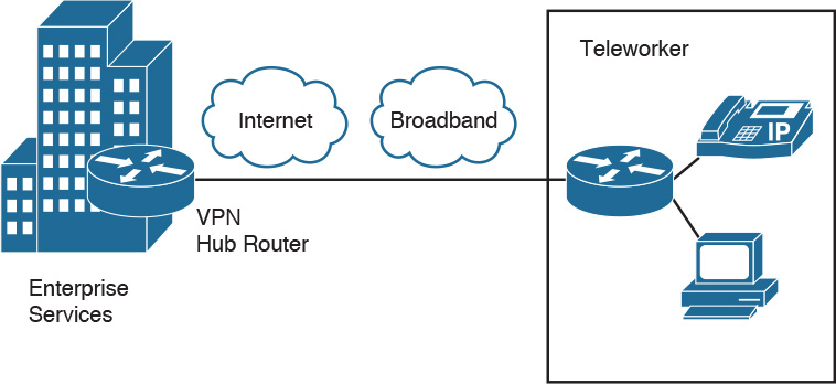
Table 2-3 summarizes the Cisco Enterprise Architecture.
High Availability Network Services
This section covers designs for high availability network services in the access layer.
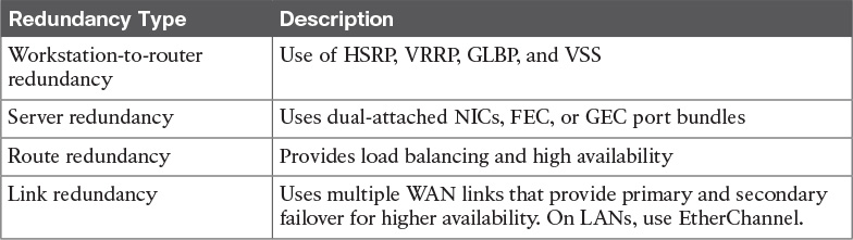
When designing a network topology for a customer who has critical systems, services, or network paths, you should determine the likelihood that these components will fail and then design redundancy where necessary. Consider incorporating one of the following types of redundancy into your design:
![]() Workstation-to-router redundancy in the building access layer
Workstation-to-router redundancy in the building access layer
![]() Server redundancy in the server farm module
Server redundancy in the server farm module
![]() Route redundancy within and between network components
Route redundancy within and between network components
![]() Link media redundancy in the access layer
Link media redundancy in the access layer
The following sections discuss each type of redundancy.
Workstation-to-Router Redundancy and LAN High Availability Protocols
When a workstation has traffic to send to a station that is not local, the workstation has many possible ways to discover the address of a router on its network segment, including the following:
![]() ARP
ARP
![]() Explicit configuration
Explicit configuration
![]() ICMP Router Discovery Protocol (RDP)
ICMP Router Discovery Protocol (RDP)
![]() RIP
RIP
![]() HSRP
HSRP
![]() VRRP
VRRP
![]() GLBP
GLBP
![]() VSS
VSS
The following sections cover each of these methods. VSS is covered earlier in the chapter.
ARP
Some IP workstations send an ARP frame to find a remote station. A router running proxy ARP can respond with its data link layer address. Cisco routers run proxy ARP by default.
Explicit Configuration
Most IP workstations must be configured with the IP address of a default router, which is sometimes called the default gateway.
In an IP environment, the most common method for a workstation to find a server is via explicit configuration (a default router). If the workstation’s default router becomes unavailable, you must reconfigure the workstation with the address of a different router. Some IP stacks enable you to configure multiple default routers, but many other IP implementations support only one default router.
RDP
RFC 1256 specifies an extension to the Internet Control Message Protocol (ICMP) that allows an IP workstation and router to run RDP to let the workstation learn a router’s address.
RIP
An IP workstation can run RIP to learn about routers, although this is not a common practice anymore and is not recommended. You should use RIP in passive mode rather than active mode. (Active mode means that the station sends RIP frames every 30 seconds.) Usually in these implementations, the workstation is a UNIX system running the routed or gated UNIX process.
HSRP
The Cisco HSRP provides a way for IP workstations that support only one default router to keep communicating on the internetwork even if their default router becomes unavailable. HSRP works by creating a virtual router that has its own IP and MAC addresses. The workstations use this virtual IP address as their default router.
HSRP routers on a LAN communicate among themselves to designate two routers as active and standby. The active router sends periodic hello messages. The other HSRP routers listen for the hello messages. If the active router fails and the other HSRP routers stop receiving hello messages, the standby router takes over and becomes the active router. Because the new active router assumes both the phantom’s IP and MAC addresses, end nodes see no change. They continue to send packets to the phantom router’s MAC address, and the new active router delivers those packets.
HSRP also works for proxy ARP. When an active HSRP router receives an ARP request for a node that is not on the local LAN, the router replies with the phantom router’s MAC address instead of its own. If the router that originally sent the ARP reply later loses its connection, the new active router can still deliver the traffic.
Figure 2-17 shows a sample implementation of HSRP.
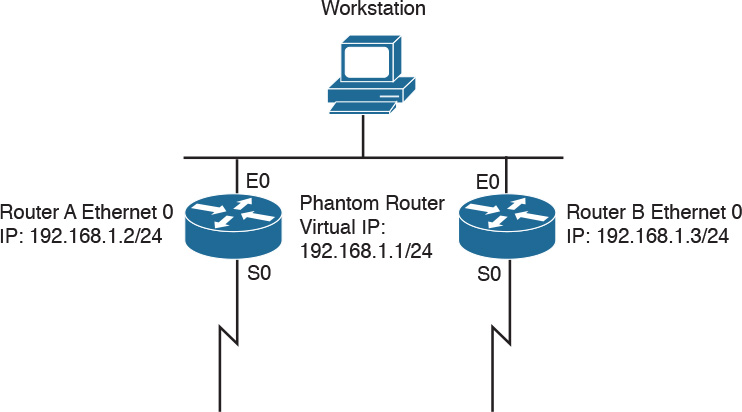
In Figure 2-17, the following sequence occurs:
1. The workstation is configured to use the phantom router (192.168.1.1) as its default router.
2. Upon booting, the routers elect Router A as the HSRP active router. The active router does the work for the HSRP phantom. Router B is the HSRP standby router.
3. When the workstation sends an ARP frame to find its default router, Router A responds with the phantom router’s MAC address.
4. If Router A goes offline, Router B takes over as the active router, continuing the delivery of the workstation’s packets. The change is transparent to the workstation.
VRRP
VRRP is a router redundancy protocol defined in RFC 3768. RFC 5768 defined VRRPv3 for both IPv4 and IPv6 networks. VRRP is based on Cisco’s HSRP, but is not compatible. VRRP specifies an election protocol that dynamically assigns responsibility for a virtual router to one of the VRRP routers on a LAN. The VRRP router controlling the IP addresses associated with a virtual router is called the master, and it forwards packets sent to these IP addresses. The election process provides dynamic failover in the forwarding responsibility should the master become unavailable. This allows any of the virtual router IP addresses on the LAN to be used as the default first-hop router by end hosts. The virtual router backup assumes the forwarding responsibility for the virtual router should the master fail.
GLBP
GLBP protects data traffic from a failed router or circuit, such as HSRP, while allowing packet load sharing between a group of redundant routers. Methods for load balancing with HSRP and VRRP work with small networks, but GLBP allows for first-hop load balancing on larger networks.
The difference in GLBP from HSRP is that it provides for load balancing between multiple redundant routers—up to four gateways in a GLBP group. It load-balances by using a single virtual IP address and multiple virtual MAC addresses. Each host is configured with the same virtual IP address, and all routers in the virtual router group participate in forwarding packets. By default, all routers within a group forward traffic and load-balance automatically. GLBP members communicate between each other through hello messages sent every three seconds to the multicast address 224.0.0.102, User Datagram Protocol (UDP) port 3222. GLBP benefits include the following:
![]() Load sharing: GLBP can be configured in a way that traffic from LAN clients can be shared by multiple routers.
Load sharing: GLBP can be configured in a way that traffic from LAN clients can be shared by multiple routers.
![]() Multiple virtual routers: GLBP supports up to 1024 virtual routers (GLBP groups) on each physical interface of a router.
Multiple virtual routers: GLBP supports up to 1024 virtual routers (GLBP groups) on each physical interface of a router.
![]() Preemption: GLBP enables you to preempt an active virtual gateway with a higher-priority backup.
Preemption: GLBP enables you to preempt an active virtual gateway with a higher-priority backup.
![]() Authentication: Simple text password authentication is supported.
Authentication: Simple text password authentication is supported.
Server Redundancy
Some environments need fully redundant (mirrored) file and application servers. For example, in a brokerage firm where traders must access data to buy and sell stocks, two or more redundant servers can replicate the data. Also, you can deploy Cisco Unified Communications Manager (CUCM) servers in clusters for redundancy. The servers should be on different networks and use redundant power supplies. To provide high availability in the server farm module, you have the following options:
![]() Single attachment: This is not recommended because it requires alternate mechanisms (HSRP, GLBP) to dynamically find an alternate router.
Single attachment: This is not recommended because it requires alternate mechanisms (HSRP, GLBP) to dynamically find an alternate router.
![]() Dual attachment: This solution increases availability by using redundant network interface cards (NIC).
Dual attachment: This solution increases availability by using redundant network interface cards (NIC).
![]() Fast EtherChannel (FEC) and Gigabit EtherChannel (GEC) port bundles: This solution bundles 2 or 4 Fast or Gigabit Ethernet links to increase bandwidth.
Fast EtherChannel (FEC) and Gigabit EtherChannel (GEC) port bundles: This solution bundles 2 or 4 Fast or Gigabit Ethernet links to increase bandwidth.
Route Redundancy
Designing redundant routes has two purposes: balancing loads and increasing availability.
Load Balancing
Most IP routing protocols can balance loads across parallel links that have equal cost. Use the maximum-paths command to change the number of links that the router will balance over for IP; the default is four, and the maximum is six. To support load balancing, keep the bandwidth consistent within a layer of the hierarchical model so that all paths have the same cost. (Cisco Enhanced Interior Gateway Routing Protocol [EIGRP] is an exception because it can load-balance traffic across multiple routes that have different metrics by using a feature called variance.)
A hop-based routing protocol does load balancing over unequal-bandwidth paths as long as the hop count is equal. After the slower link becomes saturated, packet loss at the saturated link prevents full utilization of the higher-capacity links; this scenario is called pinhole congestion. You can avoid pinhole congestion by designing and provisioning equal-bandwidth links within one layer of the hierarchy or by using a routing protocol that takes bandwidth into account.
IP load balancing in a Cisco router depends on which switching mode the router uses. Process switching load balances on a packet-by-packet basis. Fast, autonomous, silicon, optimum, distributed, and NetFlow switching load balances on a destination-by-destination basis because the processor caches information used to encapsulate the packets based on the destination for these types of switching modes.
Increasing Availability
In addition to facilitating load balancing, redundant routes increase network availability.
You should keep bandwidth consistent within a given design component to facilitate load balancing. Another reason to keep bandwidth consistent within a layer of a hierarchy is that routing protocols converge much faster on multiple equal-cost paths to a destination network.
By using redundant, meshed network designs, you can minimize the effect of link failures. Depending on the convergence time of the routing protocols, a single link failure cannot have a catastrophic effect.
You can design redundant network links to provide a full mesh or a well-connected partial mesh. In a full-mesh network, every router has a link to every other router, as shown in Figure 2-18. A full-mesh network provides complete redundancy and also provides good performance because there is just a single-hop delay between any two sites. The number of links in a full mesh is n(n–1)/2, where n is the number of routers. Each router is connected to every other router. A well-connected partial-mesh network provides every router with links to at least two other routing devices in the network.
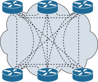
A full-mesh network can be expensive to implement in WANs because of the required number of links. In addition, groups of routers that broadcast routing updates or service advertisements have practical limits to scaling. As the number of routing peers increases, the amount of bandwidth and CPU resources devoted to processing broadcasts increases.
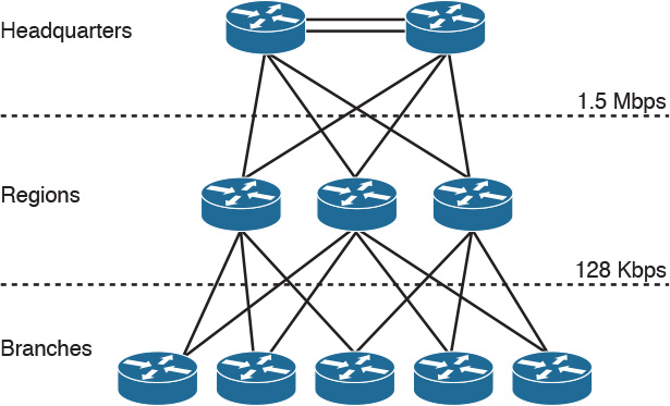
A suggested guideline is to keep broadcast traffic at less than 20 percent of the bandwidth of each link; this amount limits the number of peer routers that can exchange routing tables or service advertisements. When designing for link bandwidth, reserve 80 percent of it for data, voice, and video traffic so that the rest can be used for routing and other link traffic. When planning redundancy, follow guidelines for simple, hierarchical design. Figure 2-19 illustrates a classic hierarchical and redundant enterprise design that uses a partial-mesh rather than a full-mesh topology. For LAN designs, links between the access and distribution layers can be Fast Ethernet, with links to the core at Gigabit Ethernet speeds.
Link Media Redundancy
In mission-critical applications, it is often necessary to provide redundant media.
In switched networks, switches can have redundant links to each other. This redundancy is good because it minimizes downtime, but it can result in broadcasts continuously circling the network, which is called a broadcast storm. Because Cisco switches implement the IEEE 802.1d spanning-tree algorithm, you can avoid this looping in Spanning Tree Protocol (STP). The spanning-tree algorithm guarantees that only one path is active between two network stations. The algorithm permits redundant paths that are automatically activated when the active path experiences problems.
STP has a design limitation of only allowing one of the redundant paths to be active. VSS can be used with Catalyst 6500 switches to overcome this limitation.
You can use EtherChannel to bundle links for load balancing. Links are bundled in powers of 2 (2, 4, 8) groups. It aggregates the bandwidth of the links. Hence, two 10GE ports become 20 Gbps of bandwidth when they are bundled. For more granular load balancing, use a combination of source and destination per-port load balancing if available on the switch. In current networks, EtherChannel uses LACP, which is a standard-based negotiation protocol that is defined in IEEE 802.3ad (an older solution included the Cisco proprietary PAgP protocol). LACP helps protect against Layer 2 loops that are caused by misconfiguration. One downside is that it introduces overhead and delay when setting up the bundle.
Because WAN links are often critical pieces of the internetwork, WAN environments often deploy redundant media. As shown in Figure 2-20, you can provision backup links so that they become active when a primary link goes down or becomes congested.
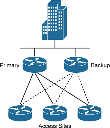
Often, backup links use a different technology. For example, it is common to use Internet VPNs to back up primary MPLS links in today’s networks. By using floating static routes, you can specify that the backup route must have a higher administrative distance (used by Cisco routers to select routing information) so that it is not normally used unless the primary route goes down.
When provisioning backup links, learn as much as possible about the physical circuit routing. Different carriers sometimes use the same facilities, meaning that your backup path might be susceptible to the same failures as your primary path. Do some investigative work to ensure that your backup really is acting as a backup.
Cisco supports Multilink Point-to-Point Protocol (MPPP), which is an Internet Engineering Task Force (IETF) standard for ISDN B-channel (or asynchronous serial interface) aggregation. It bonds multiple WAN links into a single logical channel. MPPP is defined in RFC 1990. MPPP does not specify how a router should accomplish the decision-making process to bring up extra channels. Instead, it seeks to ensure that packets arrive in sequence at the receiving router. Then, the data is encapsulated within PPP and the datagram is given a sequence number. At the receiving router, PPP uses this sequence number to re-create the original data stream. Multiple channels appear as one logical link to upper-layer protocols. For Frame Relay networks, FRF.16.1 Multilink Frame Relay is used to perform a similar function.
Table 2-4 summarizes the four main redundancy models.
References and Recommended Reading
Cisco Enterprise Teleworker Solution, http://www.cisco.com/c/en/us/solutions/enterprise-networks/teleworker/index.html.
Enterprise Architectures, http://www.cisco.com/c/en/us/solutions/enterprise-networks/index.html.
Cisco Enterprise Solutions Portal, http://www.cisco.com/c/en/us/solutions/enterprise/index.html.
Cisco TrustSec, http://www.cisco.com/c/en/us/solutions/enterprise-networks/trustsec/index.html.
Medianet at a Glance, www.cisco.com/web/solutions/medianet/docs/C45-511997-00medialnet_aag120308.pdf.
Application Performance white paper, www.cisco.com/en/US/solutions/ns1015/lippis_white_paper_application_velocity.pdf.
RFC 3768: Virtual Router Redundancy Protocol (VRRP), http://tools.ietf.org/html/rfc3768
RFC 1990: The PPP Multilink Protocol (MP).
Virtual Switching System, www.cisco.com/en/US/prod/collateral/switches/ps5718/ps9336/prod_qas0900aecd806ed74b.html.
Exam Preparation Tasks
Review All Key Topics
Review the most important topics in the chapter, noted with the Key Topics icon in the outer margin of the page. Table 2-5 lists a reference of these key topics and the page numbers on which each is found.

Complete Tables and Lists from Memory
Print a copy of Appendix D, “Memory Tables” (found on the book website), or at least the section for this chapter, and complete the tables and lists from memory. Appendix E, “Memory Tables Answer Key,” also on the website, includes completed tables and lists to check your work.
Define Key Terms
Define the following key terms from this chapter, and check your answers in the glossary:
enterprise remote branch module
Q&A
The answers to these questions appear in Appendix A, “Answers to the ‘Do I Know This Already?’ Quizzes and Q&A Questions.” For more practice with exam format questions, use the exam engine from the website.
1. True or false: The core layer of the hierarchical model does security filtering and media translation.
2. True or false: The access layer provides high availability and port security.
3. You add Communications Manager to the network as part of a Voice over IP (VoIP) solution. In which submodule of the Enterprise Architecture model should you place Communications Manager?
4. True or false: HSRP provides router redundancy.
5. Which enterprise edge submodule connects to an ISP?
6. List the six modules of the Cisco Enterprise Architecture model for network design.
7. True or false: In the Cisco Enterprise Architecture model, the network management submodule does not manage the SP edge.
8. True or false: You can implement a full-mesh network to increase redundancy and reduce a WAN’s costs.
9. How many links are required for a full mesh of six sites?
10. List and describe four options for multihoming to the SP between the enterprise edge and the SP edge. Which option provides the most redundancy?
11. To what enterprise edge submodule does the SP edge Internet submodule connect?
12. What are four benefits of hierarchical network design?
13. In an IP telephony network, in which submodule or layer are the IP phones and CUCM servers located?
14. Match the redundant model with its description:
i. Workstation-router redundancy
ii. Server redundancy
iii. Route redundancy
iv. Media redundancy
a. Cheap when implemented in the LAN and critical for the WAN.
b. Provides load balancing.
c. Host has multiple gateways.
d. Data is replicated.
15. True or false: Small-to-medium campus networks must always implement three layers of hierarchical design.
16. How many full-mesh links do you need for a network with ten routers?
17. Which layer provides routing between VLANs and security filtering?
a. Access layer
b. Distribution layer
c. Enterprise edge
d. WAN module
18. List the four modules of the enterprise edge area.
19. List the three submodules of the SP edge.
20. List the components of the Internet edge.
21. Which submodule contains firewalls, VPN concentrators, and ASAs?
a. WAN
b. VPN/remote access
c. Internet
d. Server farm
22. Which of the following describe the access layer? (Select two.)
a. High-speed data transport
b. Applies network policies
c. Performs network aggregation
d. Concentrates user access
e. Provides PoE
f. Avoids data manipulation
23. Which of the following describe the distribution layer? (Select two.)
a. High-speed data transport
b. Applies network policies
c. Performs network aggregation
d. Concentrates user access
e. Provides PoE
f. Avoids data manipulation
24. Which of the following describe the core layer? (Select two.)
a. High-speed data transport
b. Applies network policies
c. Performs network aggregation
d. Concentrates user access
e. Provides PoE
f. Avoids data manipulation
25. Which campus submodule connects to the enterprise edge module?
a. SP edge
b. WAN submodule
c. Building distribution
d. Campus core
e. Enterprise branch
f. Enterprise data center
26. Which remote module connects to the enterprise via the Internet or WAN submodules and contains a small LAN switch for users?
a. SP edge
c. Building distribution
d. Campus core
e. Enterprise branch
f. Enterprise data center
27. Which three types of servers are placed in the e-commerce submodule?
a. Web
b. Application
c. Database
d. Intranet
e. Internet
f. Public share
Use Figure 2-21 to answer questions 28–33.
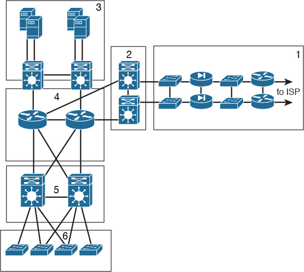
28. Which is the campus core layer?
a. Block 1
b. Block 2
c. Block 3
d. Block 4
e. Block 5
f. Block 6
29. Which is the enterprise edge?
a. Block 1
b. Block 2
c. Block 3
d. Block 4
e. Block 5
f. Block 6
30. Which is the campus access layer?
a. Block 1
b. Block 2
c. Block 3
d. Block 4
e. Block 5
f. Block 6
31. Which is the enterprise edge distribution?
a. Block 1
b. Block 2
c. Block 3
d. Block 4
e. Block 5
f. Block 6
32. Which is the campus distribution layer?
a. Block 1
b. Block 2
c. Block 3
d. Block 4
e. Block 5
f. Block 6
33. Which is the campus data center?
a. Block 1
b. Block 2
c. Block 3
d. Block 4
e. Block 5
f. Block 6
34. Which solution supports the enterprise teleworker?
a. IP telephony
b. Enterprise campus
c. Cisco Virtual Office
d. SP edge
e. Hierarchical design
f. Data Center 3.0
35. Which are two benefits of using a modular approach?
a. Simplifies the network design
b. Reduces the amount of network traffic on the network
c. Often reduces the cost and complexity of the network
d. Makes the network simple by using full mesh topologies
36. Which three modules provide infrastructure for remote users? (Select three.)
a. Teleworker module
b. WAN module
c. Enterprise branch module
d. Campus module
e. Enterprise data center
f. Core, distribution, access layers
37. Which are borderless networks infrastructure services? (Select three.)
a. IP telephony
b. Security
c. QoS
d. SP edge
e. High availability
f. Routing
38. Which module contains devices that supports AAA and stores passwords?
a. WAN module
b. VPN module
c. Server farm module
d. Internet connectivity module
e. SP edge
f. TACACS
39. Which topology is best used for connectivity in the building distribution layer?
a. Full mesh
b. Partial mesh
c. Hub and spoke
d. Dual ring
e. EtherChannel
40. What are two ways that wireless access points are used? (Choose two.)
a. Function as a hub for wireless end devices
b. Connect to the enterprise network
c. Function as a Layer 3 switch for wireless end devices
d. Provide physical connectivity for wireless end devices
e. Filter out interference from microwave devices
41. In which ways does application network services help resolve application issues? (Choose two.)
a. It can compress, cache, and optimize content.
b. Optimizes web streams, which can reduce latency and offload the web server.
c. Having multiple data centers increases productivity.
d. Improves application response times by using faster servers.
42. Which are key features of the distribution layer? (Select three.)
a. Aggregates access layer switches
b. Provides a routing boundary between access and core layers
c. Provides connectivity to end devices
d. Provides fast switching
e. Provides transport to the enterprise edge
f. Provides VPN termination
43. Which Cisco solution allows a pair of switches to act as a single logical switch?
a. HSRP
b. VSS
c. STP
d. GLB
44. Which module or layer connects the server layer to the enterprise edge?
a. Campus distribution layer
b. Campus data center access layer
c. Campus core layer
e. WAN module
f. Internet connectivity module
45. Which server type is used in the Internet connectivity module?
a. Corporate
b. Private
c. Public
d. Internal
e. Database
f. Application
46. Which server types are used in the e-commerce module for users running applications and storing data? (Select three.)
a. Corporate
b. Private
c. Public
d. Internet
e. Database
f. Application
g. Web
47. Which are submodules of the enterprise campus module? (Select two.)
a. WAN
b. LAN
c. Server farm/data center
d. Enterprise branch
e. VPN
f. Building distribution
48. Which are the three layers of the hierarchical model? (Select three.)
a. WAN layer
b. LAN layer
c. Core layer
d. Aggregation layer
e. Access layer
f. Distribution layer
g. Edge layer
49. You need to design for a packet load-sharing between a group of redundant routers. Which protocol allows you to do this?
a. HSRP
b. GLBP
c. VRRP
d. AARP
50. Which is a benefit of using network modules for network design?
a. Network availability increases.
b. Network becomes more secure.
c. Network becomes more scalable.
d. Network redundancy is higher.
51. The Cisco Enterprise Architecture takes which approach to network design?
a. It takes a functional modular approach.
b. It takes a sectional modular approach.
c. It takes a hierarchical modular approach.
d. It takes a regional modular approach.
52. Which is the recommended design geometry for routed networks?
a. Design linear point-to-point networks
b. Design in rectangular networks
c. Design in triangular networks
d. Design in circular networks
53. Which layer performs rate limiting, network access control, and broadcast suppression?
a. Core layer
b. Distribution layer
c. Access layer
d. Data link layer
54. Which layer performs routing between VLANs, filtering, and load balancing?
a. Core layer
b. Distribution layer
c. Access layer
d. Application layer
55. Which topology allows for maximum growth?
a. Triangles
b. Collapsed core-distribution
c. Full mesh
d. Core-distribution-access
56. Which layer performs port security and DHCP snooping?
a. Core layer
b. Distribution layer
c. Access layer
d. Application layer
57. Which layer performs Active Directory and messaging?
a. Core layer
b. Distribution layer
c. Access layer
d. Application layer
58. Which layers perform redundancy? (Select two.)
a. Core layer
b. Distribution layer
c. Access layer
d. Data Link Layer
59. Which statement is true regarding hierarchical network design?
a. Makes the network harder since there are many submodules to use
b. Provides better performance and network scalability
c. Prepares the network for IPv6 migration from IPv4
d. Secures the network with access filters in all layers
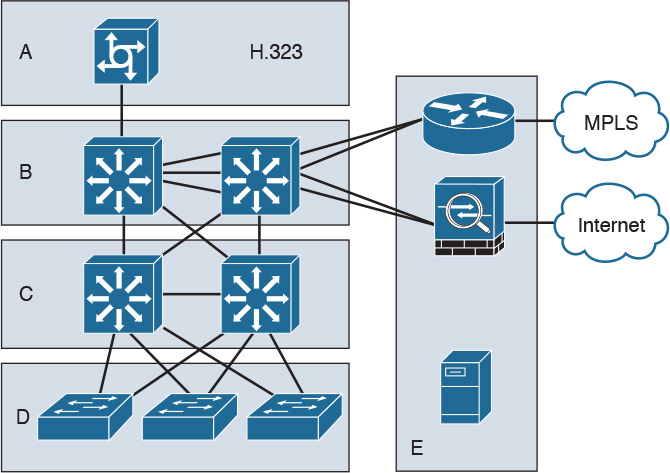
60. Based on Figure 2-22, and assuming that devices may be in more than one layer, list which devices are in each layer.
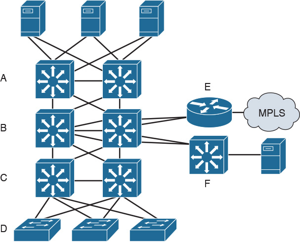
Access layer:
Distribution layer:
Core:
Use Figure 2-23 to answer questions 61–63.
61. Which section(s) belong(s) to the core layer?
62. Which section(s) belong(s) to the distribution layer?
63. Which section(s) belong(s) to the access layer?