
Chapter 2. Implementing Data Center Switching Protocols
Switching is an OSI Layer 2 (L2) process that uses a device’s Media Access Control (MAC) address to perform forwarding decisions. For high availability, switches are normally interconnected using redundant links. Switching protocols prevent Layer 2 looping when deploying switches with redundant links.
This chapter covers the following key topics:
• Spanning Tree Protocols (STP): This section provides an overview of the Layer 2 Spanning Tree Protocol, discusses the Rapid PVST+ protocol, and includes a configuration example.
• Port Channels: This section discusses the Layer 2 port channel and command-line interface (CLI) commands and includes a configuration example
• Virtual Port Channel Technology: This section covers the virtual port channel (vPC), vPC roles, vPC links, and types. It also includes a configuration example.
“Do I Know This Already?” Quiz
The “Do I Know This Already?” quiz enables you to assess whether you should read this entire chapter thoroughly or jump to the “Exam Preparation Tasks” section. If you are in doubt about your answers to these questions or your own assessment of your knowledge of the topics, read the entire chapter. Table 2-1 lists the major headings in this chapter and their corresponding “Do I Know This Already?” quiz questions. You can find the answers in Appendix A, “Answers to the ‘Do I Know This Already?’ Quizzes.”
Table 2-1 Do I Know This Already?” Section-to-Question Mapping”

Caution
The goal of self-assessment is to gauge your mastery of the topics in this chapter. If you do not know the answer to a question or are only partially sure of the answer, you should mark that question as wrong for purposes of the self-assessment. Giving yourself credit for an answer you correctly guess skews your self-assessment results and might provide you with a false sense of security.
1. Which of the following bridge IDs would win an election as root, assuming that the switches with these bridge IDs were in the same network?
a. 32769:0200.1231.1221
b. 32769:0200.3322.1112
c. 4097:0200.1122.1121
d. 4097:0200.1122.2211
e. 40961:0200.1111.1111
2. What STP feature causes an interface to be placed in a forwarding state as soon as the interface is physically active?
a. STP
b. RSTP
c. Root Guard
d. 802.1w
e. PortFast
f. Trunking
3. What are the IEEE standards that improve the original STP standard and lower convergence time? (Choose two answers.)
a. STP
b. RSTP
c. Root Guard
d. 802.1w
e. PortFast
f. Trunking
4. Which option describes how a switch in Rapid PVST+ mode responds to a topology change?
a. It immediately deletes dynamic MAC addresses that were learned by all ports on the switch.
b. It sets a timer to delete all MAC addresses that were learned dynamically by ports in the same STP instance.
c. It sets a timer to delete dynamic MAC addresses that were learned by all ports on the switch.
d. It immediately deletes all MAC addresses that were learned dynamically by ports in the same STP instance.
5. Which statements are true of the Link Aggregation Control Protocol (LACP)? (Choose three answers.)
a. LACP is used to connect to non-Cisco devices.
b. LACP packets are sent with the channel-group 1 mode desirable command.
c. LACP packets are sent with the channel-group 1 mode active command.
d. Standby interfaces should be configured with a higher priority.
e. Standby interfaces should be configured with a lower priority.
6. Which statement is true regarding the Port Aggregation Protocol (PAgP)?
a. Configuration changes made on the port channel interface apply to all physical ports assigned to the port channel interface.
b. Configuration changes made on a physical port that is a member of a port channel interface apply to the port channel interface.
c. Configuration changes are not permitted with Port Aggregation Protocol; instead, the standardized Link Aggregation Control Protocol should be used if configuration changes are required.
d. The physical port must first be disassociated from the port channel interface before any configuration changes can be made.
7. Which Fabric Extender (FEX) topologies trade deterministic bandwidth for server-link stability during FEX uplink failure? (Choose two answers.)
a. Port channel
b. Static pinning
c. Virtual port channel
d. Dynamic pinning
e. Equal-cost multipath
f. RPVST
8. What protocol do vPC peers use to synchronize forwarding-plane information and implement necessary configuration checks?
a. ARP
b. Fabric Services
c. IGMP
d. Peer-Link
9. When does the vPC suspend the port channel?
a. QoS config mismatch
b. MTU config mismatch
c. SVI config mismatch
d. ACL config mismatch
10. Which of the following statements are correct regarding a vPC? (Choose two answers.)
a. You can pair Cisco Nexus switches of different types. For example, you can deploy a vPC on Cisco Nexus Series 5000 and Cisco Nexus Series 7000 switches.
b. You can configure only one vPC domain ID on a single switch or virtual device context (VDC). It is not possible for a switch or VDC to participate in more than one vPC domain.
c. A vPC keepalive should run across a vPC peer link.
d. You can use a vPC as a Layer 2 link to establish a routing adjacency between two external routers.
Foundation Topics
Spanning Tree Protocols
Spanning Tree Protocol (STP) operation prevents Layer 2 loops. It allows only one active path to exist between any Layer 2 devices. This operation is transparent to end devices (servers or hosts), and the end device cannot detect whether it is connected to a single Layer 2 switch or a group of multiple switches.
To create a Layer 2 network with redundancy, you must have a loop-free path between all nodes in a network. An STP algorithm calculates the best loop-free path throughout a switched network. When a local-area network (LAN) port becomes active, first it starts to send and receive STP frames, which are called bridge protocol data units (BPDUs) at regular intervals. Switches do not forward these frames but use the frames to construct a loop-free path.
Multiple active paths between switches cause loops in the network. If a loop exists in a Layer 2 network, end devices might receive duplicate messages, and switches might learn end-station MAC addresses on multiple ports. These conditions result in a broadcast storm, which creates an unstable network.
STP defines a tree with a root bridge and a loop-free path from the root to all switches in the network. It forces redundant data paths into a blocked state. If a network segment in the spanning tree fails and a redundant path exists, the STP algorithm recalculates the spanning tree topology and activates the blocked path.
When two ports on a switch are part of a loop, the STP port priority and path cost determine which port on the switch is put in a forwarding state and which port is put in a blocking state.
![]()
STP Topology
All switches in an extended local-area network that participate in a spanning tree gather information about other switches in the network by exchanging BPDUs. This exchange of BPDUs results in the following actions:
• The system elects a unique root switch for the spanning tree network topology.
• The system elects a designated switch for each LAN segment.
• The system eliminates any loops in the switched network by placing redundant interfaces in a backup state; all paths that are not needed to reach the root switch from anywhere in the switched network are placed in an STP blocked state.
The topology on an active switched network is determined by the following:
• The unique switch identifier Media Access Control (MAC) address of the switch that is associated with each switch
• The path cost to the root that is associated with each interface
• The port identifier that is associated with each interface
In a switched network, the root switch is the logical center of the spanning tree topology. STP uses BPDUs to elect the root switch and root port for the switched network, as well as the root port and designated port for each switched segment.
![]()
STP Port Types
Cisco NX-OS has three main STP port types: an edge port, a network port, or a normal port. A port can be in only one of these states at a given time. The default spanning tree port type is normal. Depending on the type of device to which the interface is connected, you can configure a spanning tree port as one of these port types.
• Spanning tree edge ports: Edge ports are normally connected to end hosts. An edge port can be either an access port or a trunk port. The edge port interface immediately transitions to the forwarding state without moving through the blocking or learning states. (This immediate transition was previously configured as the Cisco-proprietary feature PortFast.) Interfaces that are connected to hosts should not receive STP bridge protocol data units.
Note
If a port connected to another switch set as an edge port, that might create a bridging loop.
• Spanning tree network ports: Network ports are normally connected only to switches or bridges. Bridge assurance is enabled only on network ports.
Note
If you mistakenly configure ports that are connected to hosts or other edge devices as spanning tree network ports, those ports automatically move into the blocking state.
• Spanning tree normal ports: Normal ports can be connected to either hosts, switches, or bridges. These ports function as normal spanning tree ports. The default spanning tree interface is normal ports.
STP Extensions
Different STP extensions are used to protect the switch against certain problems that can cause bridging loops in the network. Loops can be caused by several problems:
• Unidirectional links
• Device malfunctions
• Configuration errors
• External system forwarding (hub or non-STP switch, or end-host network bridging)
NX-OS has added many STP extensions that enhance loop prevention, protect against some possible user misconfigurations, and provide better control over the protocol parameters. Here’s a quick summary of these extensions:
• STP Bridge Assurance: Spanning tree Bridge Assurance is one of those features that help prevent bridging loops in Layer 2 networks.
• BPDU Guard: This extension disables ports that receive a BPDU frame; it is useful for edge ports that should never be connected to another switch.
• BPDU Filtering: This extension prevents the switch from sending or even receiving BPDUs on a specified edge port.
• Loop Guard: This extension protects against network interfaces that malfunction. Loop Guard is useful only in switched networks where devices are connected by point-to-point links. On a point-to-point link, a designated bridge cannot disappear unless it sends an inferior BPDU or brings the link down.
• Root Guard: This extension prevents a port from becoming a root port or a blocked port.
STP Bridge Assurance
When Bridge Assurance is enabled, BPDUs are sent on all switch interfaces, including blocked interfaces like the alternate or backup port. When an interface doesn’t receive a BPDU for a certain time, the interface goes into the blocking state, as shown in Figure 2-1. When a second switch fails and stops sending BPDUs, switches one and three disable the ports facing switch two to prevent any loop.
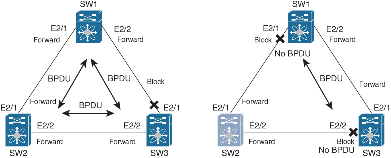
Figure 2-1 STP Bridge Assurance
When the interface receives BPDUs again, the interface is unblocked and goes through the normal spanning tree port states again. This helps prevent issues (that is, unidirectional link failures or switch failures where the switch does forward Ethernet frames, but STP is malfunctioning) where, for whatever reason, an interface doesn’t receive BPDUs again and a blocked interface goes into the forwarding state, causing a bridging loop.
NX-OS has STP Bridge Assurance enabled by default, and it can only be disabled globally. Also, Bridge Assurance can be enabled only on spanning tree network ports that are point-to-point links. Finally, both ends of the link must have Bridge Assurance enabled. If the device on one side of the link has Bridge Assurance enabled and the device on the other side either does not support Bridge Assurance or does not have this feature enabled, the connecting port is blocked.
Note
STP Bridge Assurance is supported only by Rapid PVST+ and MST. Legacy 802.1D spanning tree does not support Bridge Assurance.
BPDU Guard
The BPDU Guard feature must be enabled on a port that should never receive a BPDU from its connected device—for example, a workstation, server, or printer. End devices are not supposed to generate BPDUs because, in a normal network environment, BPDU messages are exchanged only by network switches.
If BPDU Guard is configured globally, it affects only operational spanning tree edge ports. In a valid configuration, LAN edge interfaces do not receive BPDUs. A BPDU that is received by an edge LAN interface signals an invalid configuration, such as the connection of an unauthorized switch. BPDU Guard, when enabled globally, shuts down any spanning tree edge ports that receive a BPDU and generates an err-disable alert.
BPDU Guard provides a secure response to invalid configurations because an administrator must manually put the LAN interface back in service after an invalid configuration.
BPDU Filter
BPDU Filter prevents the switch from sending or even receiving BPDUs on specified ports.
When configured globally, BPDU Filtering applies to all operational spanning tree edge ports. Ports should connect to hosts only, which typically drop BPDUs. If an operational spanning tree edge port receives a BPDU, it immediately returns to a normal spanning tree port type and moves through the regular transitions. In that case, BPDU Filtering is disabled on this port, and the spanning tree resumes sending BPDUs on this port.
Note
Use care when configuring BPDU Filtering per interface. Explicitly configuring BPDU Filtering on a port that is not connected to a host can result in bridging loops because the port will ignore any BPDU that it receives and go to forwarding.
Loop Guard
Loop Guard protects networks from loops that are caused by the following:
• Network interfaces that malfunction
• Busy CPUs
• Anything that prevents the normal forwarding of BPDUs
An STP loop occurs when a blocking port in a redundant topology erroneously transitions to the forwarding state. This transition usually happens because one of the ports in a physically redundant topology (not necessarily the blocking port) stops receiving BPDUs.
Loop Guard is useful only in switched networks where devices are connected by point-to-point links. On a point-to-point link, a designated bridge cannot disappear unless it sends an inferior BPDU or brings the link down.
You can use Loop Guard to determine if a root port or an alternate/backup root port receives BPDUs. If the port does not receive BPDUs, Loop Guard puts the port into an inconsistent state (blocking) until the port starts to receive BPDUs again. A port in an inconsistent state does not transmit BPDUs. If the port receives BPDUs again, the protocol removes its loop-inconsistent condition, and the STP determines the port state because such recovery is automatic. Loop Guard isolates the failure and allows STP to converge to a stable topology without the failed link or bridge. Disabling Loop Guard moves all loop-inconsistent ports to the listening state.
Root Guard
Root Guard does not allow that port to become a root port. If a port-received BPDU triggers an STP convergence that makes that designated port become a root port, that port is put into a root-inconsistent (blocked) state. After the port stops sending superior BPDUs, the port is unblocked again. Through STP, the port moves to the forwarding state because recovery is automatic.
If Root Guard is enabled on a specific interface, it applies this functionality to all virtual local-area networks (VLANs) to which that interface belongs.
Root Guard is used to enforce the root bridge placement in the network. It ensures that the port on which Root Guard is enabled is the designated port. Normally, root bridge ports are all designated ports, unless two or more of the ports of the root bridge are connected. If the bridge receives superior BPDUs on a Root Guard–enabled port, the bridge moves this port to a root-inconsistent STP state. In this way, Root Guard enforces the position of the root bridge.
Unidirectional Link Detection
Unidirectional Link Detection (UDLD) is a Cisco proprietary Layer 2 protocol that enables the devices to automatically detect the loss of bidirectional communication on a link. A unidirectional link occurs whenever traffic sent by a local device is received by its neighbor but traffic from the neighbor is not received by the local device.
All connected devices must support UDLD for the protocol to successfully identify and disable unidirectional links. When UDLD detects a unidirectional link, it disables the affected port and generates an alert. Unidirectional links can cause a variety of problems, including spanning tree topology loops.
UDLD supports two modes of operation: normal (the default) and aggressive. In normal mode, UDLD can detect unidirectional links due to misconnected ports on fiber-optic connections. In aggressive mode, UDLD can also detect unidirectional links due to one-way traffic on fiber-optic and twisted-pair links and to misconnected ports on fiber-optic links, as shown in Figure 2-2.
![]()

Figure 2-2 UDLD Detection of a Unidirectional Link
Rapid PVST+
![]()
Rapid PVST+ provides for rapid recovery of connectivity following the failure of a network device, a switch port, or a LAN. It provides rapid convergence for edge ports. Rapid PVST+ is the IEEE 802.1w (RSTP) standard implemented per VLAN. A single instance of STP runs on each configured VLAN (if you do not manually disable STP). Each Rapid PVST+ instance on a VLAN has a single root switch. You can enable and disable STP on a per-VLAN basis when you are running Rapid PVST+.
Note
Rapid PVST+ is the default STP mode for Nexus switches.
Rapid PVST+ uses point-to-point wiring to provide rapid convergence of the spanning tree. The spanning tree reconfiguration can occur in less than one second with Rapid PVST+ (in contrast to 50 seconds with the default settings in the 802.1D STP).
Note
Rapid PVST+ supports one STP instance for each VLAN.
Using Rapid PVST+, STP convergence occurs rapidly. Each designated or root port in the STP sends out a BPDU every two seconds by default. On a designated or root port in the topology, if hello messages are missed three consecutive times, or if the maximum age expires, the port immediately flushes all protocol information in the table. A port considers that it loses connectivity to its direct neighbor root or designated port if it misses three BPDUs or if the maximum age expires. This rapid aging of the protocol information allows quick failure detection. The switch automatically checks the PVID.
Rapid PVST+ ports are connected through point-to-point links as follows:
• Edge ports: When a port is configured as an edge port on an RSTP switch, the edge port immediately transitions to the forwarding state. You should configure only on ports that connect to a single end device as edge ports. Edge ports do not generate topology changes when the link changes.
• Root ports: If Rapid PVST+ selects a new root port, it blocks the old root port and immediately transitions the new root port to the forwarding state.
• Point-to-point links: If a port connected to another port through a point-to-point link and the local port becomes a designated port, it negotiates a rapid transition with the other port by using the proposal-agreement handshake to ensure a loop-free topology.
Rapid PVST+ achieves rapid transition to the forwarding state only on edge ports and point-to-point links. Although the link type is configurable, the system automatically derives the link type information from the duplex setting of the port. Full-duplex ports are assumed to be point-to-point ports, and half-duplex ports are assumed to be shared ports.
Edge ports do not generate topology changes, but all other designated and root ports generate a topology change (TC) BPDU when they either fail to receive three consecutive BPDUs from the directly connected neighbor or the maximum age times out. At this point, the designated or root port sends out a BPDU with the TC flag set. The BPDUs continue to set the TC flag as long as the TC While timer runs on that port. The value of the TC While timer is the value set for the hello time plus one second. The initial detector of the topology change immediately floods this information throughout the entire topology.
When Rapid PVST+ detects a topology change, the protocol does the following:
• Starts the TC While timer with a value equal to twice the hello time for all the non-edge root and designated ports, if necessary.
• Flushes the MAC addresses associated with all these ports.
The topology change notification floods quickly across the entire topology. The system flushes dynamic entries immediately on a per-port basis when it receives a topology change.
Figure 2-3 shows Switch A (a root switch set the TC bits in its BPDU). This BPDU floods to the whole network. Normally, the TC bit is set by the root for a period of max_age + forward_delay seconds, which is 10+15=35 seconds by default.
![]()

Figure 2-3 Topology Change (TC) BPDU Flood
Note
The TCA flag is used only when the switch interacts with switches running legacy 802.1D STP.
The proposal and agreement sequence then quickly propagate toward the edge of the network and quickly restore connectivity after a topology change.
![]()
Rapid PVST+ Ports
Rapid PVST+ provides rapid convergence of the spanning tree by assigning port roles and learning the active topology. Rapid PVST+ builds on the 802.1D STP to select the switch with the highest priority (lowest numerical priority value) as the root bridge. Rapid PVST+ then assigns one of these port roles to individual ports, as in Figure 2-4:
• Root port: Provides the best path (lowest cost) when the switch forwards packets to the root bridge.
• Designated port: Connects to the designated switch, which incurs the lowest path cost when forwarding packets from that LAN to the root bridge. The port through which the designated switch is attached to the LAN is called the designated port.
• Alternate port: Offers an alternate path toward the root bridge to the path provided by the current root port. An alternate port provides a path to another switch in the topology.
• Backup port: Acts as a backup for the path provided by a designated port toward the leaves of the spanning tree. A backup port can exist only when two ports are connected in a loopback by a point-to-point link or when a switch has two or more connections to a shared LAN segment. A backup port provides another path in the topology to the switch.
• Disabled port: Has no role within the operation of the spanning tree.
In a stable topology with consistent port roles throughout the network, Rapid PVST+ ensures that every root port and designated port immediately transitions to the forwarding state while all alternate and backup ports are always in the blocking state. Designated ports start in the blocking state. The port state controls the operation of the forwarding and learning processes.

Figure 2-4 Rapid PVST+ Port Roles
Due to propagation delays, topology changes can take place at different times and at different places in a Layer 2 network. When a switch LAN port transitions directly from nonparticipation in the spanning tree topology to the forwarding state, it can create temporary data loops. Ports must wait for new topology information to propagate through the switch LAN before starting to forward frames.
Each LAN port on software using Rapid PVST+ or MST exists in one of the following four states:
• Blocking: The switch LAN port does not participate in frame forwarding.
• Learning: The switch LAN port prepares to participate in frame forwarding.
• Forwarding: The switch LAN port forwards frames.
• Disabled: The switch LAN port does not participate in STP and does not forward frames.
Table 2-2 list the possible operational and Rapid PVST+ states for ports and the corresponding inclusion in the active topology.
![]()
Table 2-2 Port State Active Topology

To control STP selection, you can set cost value to change the selection. Lower cost values to switch LAN interfaces are selected first, and higher cost values to switch LAN interfaces are selected last. If all switch LAN interfaces have the same cost value, STP puts the switch LAN interface with the lowest number in the forwarding state and blocks other interfaces.
On access ports, you assign port cost by the port. On trunk ports, port cost can be assigned by VLAN. The same port cost needs to be assigned to all the VLANs on a trunk port.
Cisco NX-OS supports two different path-cost methods: short and long methods. A short path-cost is a 16-bit value and ranges from 1 to 65,535. However, a long path-cost is a 32-bit value, which extends the value up to 200,000,000.
Note
Rapid PVST+ uses the short (16-bit) path-cost method to calculate the cost by default.
The STP port path-cost default value is determined from the media speed and path-cost calculation method of a LAN interface (see Table 2-3). If a loop occurs, STP considers the port cost when selecting a switch LAN interface to put into the forwarding state.
![]()
Table 2-3 Default Port Cost

If a loop occurs and multiple ports have the same path-cost, Rapid PVST+ considers the port priority when selecting which switch LAN port to put into the forwarding state. Lower priority values are selected first, and higher priority values are selected last.
If all switch LAN ports have the same priority value, Rapid PVST+ puts the switch LAN port with the lowest LAN port number in the forwarding state and blocks other LAN ports. The possible priority range is from 0 through 224 (the default is 128), configurable in increments of 32. Software uses the port priority value when the LAN port is configured as an access port and uses VLAN port priority values when the switch LAN port is configured as a trunk port.
Spanning Tree Configurations and Verifications
Table 2-4 lists STP default parameters, and Table 2-5 lists Rapid PVST+ and UDLS default parameters. You can alter these parameters as necessary to optimize protocol functionality.
Table 2-4 STP Extension Default Settings

Table 2-5 Rapid PVST+ and UDLD Default Settings


Note
No license is required for STP extensions. Any feature not included in a license package is bundled with the Cisco NX-OS system images. For a complete explanation of the Cisco NX-OS licensing scheme, see the Cisco NX-OS Licensing Guide.
STP, Rapid PVST+, and UDLD have the following recommended configurations and limitations:
• Port settings recommendations are as follows:
• You should connect STP network ports only to switches.
• You should configure host ports as STP edge ports and not as network ports.
• If you enable STP network port types globally, ensure that you manually configure all ports connected to hosts as STP edge ports.
• You should configure all access and trunk ports connected to Layer 2 hosts as edge ports.
• You should enable BPDU Guard on all edge ports.
• Bridge Assurance runs only on point-to-point spanning tree network ports. You must configure each side of the link for this feature.
• Enabling Loop Guard globally works only on point-to-point links.
• Enabling Loop Guard per interface works on both shared and point-to-point links.
• Root Guard forces a port to always be a designated port; it does not allow a port to become a root port. Loop Guard is effective only if the port is a root port or an alternate port. You cannot enable Loop Guard and Root Guard on a port at the same time.
• Spanning tree always chooses the first operational port in the channel to send the BPDUs. If that link becomes unidirectional, Loop Guard blocks the channel, even if other links in the channel are functioning properly.
• If you group together a set of ports that are already blocked by Loop Guard to form a channel, spanning tree loses all the state information for those ports, and the new channel port may obtain the forwarding state with a designated role.
• If a channel is blocked by Loop Guard and the channel members go back to an individual link status, spanning tree loses all the state information. The individual physical ports may obtain the forwarding state with the designated role, even if one or more of the links that formed the channel are unidirectional.
Note
You can enable Unidirectional Link Detection (UDLD) aggressive mode to isolate the link failure. A loop may occur until UDLD detects the failure, but Loop Guard will not be able to detect it.
• It is recommended to enable Root Guard on ports that connect to network devices that are not under direct administrative control.
• The Rapid PVST+ maximum number of VLANs and ports is 16,000.
• The port channel bundle is considered a single port. The port cost is the aggregation of all the configured port costs assigned to that channel.
• For private VLANs, on a normal VLAN trunk port, the primary and secondary private VLANs are two different logical ports and must have the exact STP topology. On access ports, STP sees only the primary VLAN.
• Do not change timers because changing timers can adversely affect stability.
• Keep user traffic off the management VLAN; keep the management VLAN separate from the user data.
• Choose the distribution and core layers as the location of the primary and secondary root switches.
• When you connect two Cisco devices through 802.1Q trunks, the switches exchange spanning tree BPDUs on each VLAN allowed on the trunks. The BPDUs on the native VLAN of the trunk are sent untagged to the reserved 802.1D spanning tree multicast MAC address (01-80-C2-00-00-00). The BPDUs on all VLANs on the trunk are sent tagged to the reserved Cisco Shared Spanning Tree Protocol (SSTP) multicast MAC address (01-00-0c-cc-cc-cd).
Tables 2-6 through 2-8 show the most-used STP configuration commands. For a full list of commands, refer to the Nexus Interface Configuration Guide links provided in the “References” at the end of the chapter.
Table 2-6 STP Global-Level Commands

Table 2-7 STP Interface-Level Commands

Table 2-8 STP Global-Level Verification Commands

Figure 2-5 shows the network topology for the configuration that follows, which demonstrates how to configure or modify a spanning tree.

Figure 2-5 STP Network Topology
Example 2-1 shows the spanning tree configuration for the root switch (SW9621-1). The configuration changes the default spanning tree port to a network port and enables default bpdugard and pbdufilter for edge ports. It also lowers all VLAN priorities to make sure the switch will be elected as a root. Examples 2-2 and 2-3 show the interface configurations with a spanning tree summary and details.
Example 2-1 SW9621-1 Global Configurations
SW9621-1(config)# spanning-tree port type edge bpduguard default
SW9621-1(config)# spanning-tree port type edge bpdufilter default
SW9621-1(config)# spanning-tree port type network default
SW9621-1(config)# spanning-tree vlan 1-3967 priority 24576
Example 2-2 SW9621-1 Interface Configurations
SW9621-1(config)# interface Ethernet2/1
SW9621-1(config-if)# switchport
SW9621-1(config-if)# switchport mode trunk
SW9621-1(config-if)# spanning-tree guard root
SW9621-1(config)# interface Ethernet2/2
SW9621-1(config-if)# switchport
SW9621-1(config-if)# switchport mode trunk
SW9621-1(config-if)# spanning-tree guard root
Example 2-3 SW9621-1 Verifications
SW9621-1# show spanning-tree summary
Switch is in rapid-pvst mode
Root bridge for: VLAN0001, VLAN0100, VLAN0200
Port Type Default is network
Edge Port [PortFast] BPDU Guard Default  is enabled
Edge Port [PortFast] BPDU Filter Default is enabled
Bridge Assurance                         is enabled
Loopguard Default                        is disabled
Pathcost method used                     is short
STP-Lite                                 is enabled

Name                   Blocking Listening Learning Forwarding STP    Active
---------------------- -------- --------- -------- ---------- ----------
VLAN0001                     0         0        0             2      2
VLAN0100                     0         0        0             2      2
VLAN0200                     0         0        0             2      2
---------------------- -------- --------- -------- ---------- ----------
3 vlans                      0         0        0             6      6

SW9621-1# show spanning-tree
VLAN0001
  Spanning tree enabled protocol rstp
  Root ID    Priority    24577
             Address     fa16.3e93.f9cc
             This bridge is the root
             Hello Time  2  sec  Max Age 20 sec  Forward Delay 15 sec

  Bridge ID  Priority    24577  (priority 24576 sys-id-ext 1)
             Address     fa16.3e93.f9cc
             Hello Time  2  sec  Max Age 20 sec  Forward Delay 15 sec

Interface        Role Sts Cost      Prio.Nbr Type
---------------- ---- --- --------- -------- --------------------------------
Eth2/1           Desg FWD 4         128.257  Network P2p
Eth2/2           Desg FWD 4         128.258  Network P2p

VLAN0100
  Spanning tree enabled protocol rstp
  Root ID    Priority    24676
             Address     fa16.3e93.f9cc
             This bridge is the root
             Hello Time  2  sec  Max Age 20 sec  Forward Delay 15 sec

  Bridge ID  Priority    24676  (priority 24576 sys-id-ext 100)
             Address     fa16.3e93.f9cc
             Hello Time  2  sec  Max Age 20 sec  Forward Delay 15 sec

Interface        Role Sts Cost      Prio.Nbr Type
---------------- ---- --- --------- -------- --------------------------------
Eth2/1           Desg FWD 4         128.257  Network P2p
Eth2/2           Desg FWD 4         128.258  Network P2p

VLAN0200
  Spanning tree enabled protocol rstp
  Root ID    Priority    24776
             Address     fa16.3e93.f9cc
             This bridge is the root
             Hello Time  2  sec  Max Age 20 sec  Forward Delay 15 sec

  Bridge ID  Priority    24776  (priority 24576 sys-id-ext 200)
             Address     fa16.3e93.f9cc
             Hello Time  2  sec  Max Age 20 sec  Forward Delay 15 sec

Interface        Role Sts Cost      Prio.Nbr Type
---------------- ---- --- --------- -------- --------------------------------
Eth2/1           Desg FWD 4         128.257  Network P2p
Eth2/2           Desg FWD 4         128.258  Network P2p

SW9621-1# show spanning-tree detail
 VLAN0001 is executing the rstp compatible Spanning Tree protocol
  Bridge Identifier has priority 24576, sysid 1, address fa16.3e93.f9cc
  Configured hello time 2, max age 20, forward delay 15
  We are the root of the spanning tree
  Topology change flag not set, detected flag not set
  Number of topology changes 5 last change occurred 0:04:22 ago
          from Ethernet2/1
  Times:  hold 1, topology change 35, notification 2
          hello 2, max age 20, forward delay 15
  Timers: hello 0, topology change 0, notification 0

 Port 257 (Ethernet2/1) of VLAN0001 is designated forwarding
   Port path cost 4, Port priority 128, Port Identifier 128.257
   Designated root has priority 24577, address fa16.3e93.f9cc
   Designated bridge has priority 24577, address fa16.3e93.f9cc
   Designated port id is 128.257, designated path cost 0
   Timers: message age 0, forward delay 0, hold 0
   Number of transitions to forwarding state: 1
   The port type is network by default
   Link type is point-to-point by default
   Root guard is enabled
   BPDU: sent 4469, received 4466

 Port 258 (Ethernet2/2) of VLAN0001 is designated forwarding
   Port path cost 4, Port priority 128, Port Identifier 128.258
   Designated root has priority 24577, address fa16.3e93.f9cc
   Designated bridge has priority 24577, address fa16.3e93.f9cc
   Designated port id is 128.258, designated path cost 0
   Timers: message age 0, forward delay 0, hold 0
   Number of transitions to forwarding state: 1
   The port type is network by default
   Link type is point-to-point by default
   Root guard is enabled
   BPDU: sent 4470, received 4467

 VLAN0100 is executing the rstp compatible Spanning Tree protocol
  Bridge Identifier has priority 24576, sysid 100, address fa16.3e93.f9cc
  Configured hello time 2, max age 20, forward delay 15
  We are the root of the spanning tree
  Topology change flag not set, detected flag not set
  Number of topology changes 5 last change occurred 0:04:22 ago
          from Ethernet2/1
  Times:  hold 1, topology change 35, notification 2
          hello 2, max age 20, forward delay 15
  Timers: hello 0, topology change 0, notification 0

 Port 257 (Ethernet2/1) of VLAN0100 is designated forwarding
   Port path cost 4, Port priority 128, Port Identifier 128.257
   Designated root has priority 24676, address fa16.3e93.f9cc
   Designated bridge has priority 24676, address fa16.3e93.f9cc
   Designated port id is 128.257, designated path cost 0
   Timers: message age 0, forward delay 0, hold 0
   Number of transitions to forwarding state: 1
   The port type is network by default
   Link type is point-to-point by default
   Root guard is enabled
   BPDU: sent 4468, received 4466

 Port 258 (Ethernet2/2) of VLAN0100 is designated forwarding
   Port path cost 4, Port priority 128, Port Identifier 128.258
   Designated root has priority 24676, address fa16.3e93.f9cc
   Designated bridge has priority 24676, address fa16.3e93.f9cc
   Designated port id is 128.258, designated path cost 0
   Timers: message age 0, forward delay 0, hold 0
   Number of transitions to forwarding state: 1
   The port type is network by default
   Link type is point-to-point by default
   Root guard is enabled
   BPDU: sent 4469, received 4467

 VLAN0200 is executing the rstp compatible Spanning Tree protocol
  Bridge Identifier has priority 24576, sysid 200, address fa16.3e93.f9cc
  Configured hello time 2, max age 20, forward delay 15
  We are the root of the spanning tree
  Topology change flag not set, detected flag not set
  Number of topology changes 5 last change occurred 0:04:22 ago
          from Ethernet2/2
  Times:  hold 1, topology change 35, notification 2
          hello 2, max age 20, forward delay 15
  Timers: hello 0, topology change 0, notification 0

 Port 257 (Ethernet2/1) of VLAN0200 is designated forwarding
   Port path cost 4, Port priority 128, Port Identifier 128.257
   Designated root has priority 24776, address fa16.3e93.f9cc
   Designated bridge has priority 24776, address fa16.3e93.f9cc
   Designated port id is 128.257, designated path cost 0
   Timers: message age 0, forward delay 0, hold 0
   Number of transitions to forwarding state: 1
   The port type is network by default
   Link type is point-to-point by default
   Root guard is enabled
   BPDU: sent 4469, received 4468

 Port 258 (Ethernet2/2) of VLAN0200 is designated forwarding
   Port path cost 4, Port priority 128, Port Identifier 128.258
   Designated root has priority 24776, address fa16.3e93.f9cc
   Designated bridge has priority 24776, address fa16.3e93.f9cc
   Designated port id is 128.258, designated path cost 0
   Timers: message age 0, forward delay 0, hold 0
   Number of transitions to forwarding state: 1
   The port type is network by default
   Link type is point-to-point by default
   Root guard is enabled
   BPDU: sent 4468, received 4467
Example 2-4 shows spanning tree configurations for the second switch (SW9621-2). The configuration changes the default spanning tree port to a network port and enables bpdugard and pbdufilter for edge ports. Examples 2-5 and 2-6 show the interface configurations for the root switch with a spanning tree summary.
Example 2-4 SW9621-2 Global Configurations
SW9621-2(config)# spanning-tree port type edge bpduguard default
SW9621-2(config)# spanning-tree port type edge bpdufilter default
SW9621-2(config)# spanning-tree port type network default
Example 2-5 SW9621-2 Interface Configurations
SW9621-2(config)# interface Ethernet2/1
SW9621-2(config-if)# switchport
SW9621-2(config-if)# switchport mode trunk
SW9621-2(config)# interface Ethernet2/2
SW9621-2(config-if)# switchport
SW9621-2(config-if)# switchport mode trunk
SW9621-2(config)# interface Ethernet2/3
SW9621-2(config-if)# switchport
SW9621-2(config-if)# switchport access vlan 100
SW9621-2(config-if)# spanning-tree port type edge
SW9621-2(config-if)# no shutdown
Example 2-6 SW9621-2 Verifications
W9621-2# show spanning-tree summary
Switch is in rapid-pvst mode
Root bridge for: none
Port Type Default is network
Edge Port [PortFast] BPDU Guard Default  is enabled
Edge Port [PortFast] BPDU Filter Default is enabled
Bridge Assurance                         is enabled
Loopguard Default                        is disabled
Pathcost method used                     is short
STP-Lite                                 is enabled

Name                   Blocking Listening Learning Forwarding STP Active
---------------------- -------- --------- -------- ---------- ----------
VLAN0001                     0         0        0          2          2
VLAN0100                     0         0        0          3          3
VLAN0200                     0         0        0          2          2
---------------------- -------- --------- -------- ---------- ----------
3 vlans                      0         0        0          7          7

SW9621-2# show spanning-tree

VLAN0001
  Spanning tree enabled protocol rstp
  Root ID    Priority    24577
             Address     fa16.3e93.f9cc
             Cost        4
             Port        257 (Ethernet2/1)
             Hello Time  2  sec  Max Age 20 sec  Forward Delay 15 sec

  Bridge ID  Priority    32769  (priority 32768 sys-id-ext 1)
             Address     fa16.3e4d.d715
             Hello Time  2  sec  Max Age 20 sec  Forward Delay 15 sec

Interface        Role Sts Cost      Prio.Nbr Type
---------------- ---- --- --------- -------- --------------------------------
Eth2/1           Root FWD 4         128.257  Network P2p
Eth2/2           Desg FWD 4         128.258  Network P2p

VLAN0100
  Spanning tree enabled protocol rstp
  Root ID    Priority    24676
             Address     fa16.3e93.f9cc
             Cost        4
             Port        257 (Ethernet2/1)
             Hello Time  2  sec  Max Age 20 sec  Forward Delay 15 sec

  Bridge ID  Priority    32868  (priority 32768 sys-id-ext 100)
             Address     fa16.3e4d.d715
             Hello Time  2  sec  Max Age 20 sec  Forward Delay 15 sec

Interface        Role Sts Cost      Prio.Nbr Type
---------------- ---- --- --------- -------- --------------------------------
Eth2/1           Root FWD 4         128.257  Network P2p
Eth2/2           Desg FWD 4         128.258  Network P2p
Eth2/3           Desg FWD 4         128.259  Edge P2p

VLAN0200
  Spanning tree enabled protocol rstp
  Root ID    Priority    24776
             Address     fa16.3e93.f9cc
             Cost        4
             Port        257 (Ethernet2/1)
             Hello Time  2  sec  Max Age 20 sec  Forward Delay 15 sec

  Bridge ID  Priority    32968  (priority 32768 sys-id-ext 200)
             Address     fa16.3e4d.d715
             Hello Time  2  sec  Max Age 20 sec  Forward Delay 15 sec

Interface        Role Sts Cost      Prio.Nbr Type
---------------- ---- --- --------- -------- --------------------------------
Eth2/1           Root FWD 4         128.257  Network P2p
Eth2/2           Desg FWD 4         128.258  Network P2p
Example 2-7 shows the spanning tree configuration for the third switch (SW9621-3). The configuration changes the default spanning tree port to a network port and enables bpdugard and pbdufilter for the edge ports. Examples 2-8 and 2-9 show the interface configurations for the root switch with a spanning tree summary.
Example 2-7 SW9621-3 Global Configurations
SW9621-3(config)# spanning-tree port type edge bpduguard default
SW9621-3(config)# spanning-tree port type edge bpdufilter default
SW9621-3(config)# spanning-tree port type network default
Example 2-8 SW9621-3 Interface Configurations
SW9621-3(config)# interface Ethernet2/1
SW9621-3(config-if)# switchport
SW9621-3(config-if)# switchport mode trunk
SW9621-3(config)# interface Ethernet2/2
SW9621-3(config-if)# switchport
SW9621-3(config-if)# switchport mode trunk
SW9621-3(config)# interface Ethernet2/3
SW9621-3(config-if)# switchport
SW9621-3(config-if)# switchport access vlan 200
SW9621-3(config-if)# spanning-tree port type edge
SW9621-3(config-if)# no shutdown
Example 2-9 SW9621-3 Verifications
SW9621-3# show spanning-tree summary
Switch is in rapid-pvst mode
Root bridge for: none
Port Type Default is network
Edge Port [PortFast] BPDU Guard Default  is enabled
Edge Port [PortFast] BPDU Filter Default is enabled
Bridge Assurance                         is enabled
Loopguard Default                        is disabled
Pathcost method used                     is short
STP-Lite                                 is enabled

Name                   Blocking Listening Learning Forwarding STP Active
---------------------- -------- --------- -------- ---------- ----------
VLAN0001                     2         0        0          1          3
VLAN0100                     1         0        0          1          2
VLAN0200                     2         0        0          1          3
---------------------- -------- --------- -------- ---------- ----------
3 vlans                      5         0        0          3          8

SW9621-3# show spanning-tree

VLAN0001
  Spanning tree enabled protocol rstp
  Root ID    Priority    24577
             Address     fa16.3e93.f9cc
             Cost        4
             Port        257 (Ethernet2/1)
             Hello Time  2  sec  Max Age 20 sec  Forward Delay 15 sec

  Bridge ID  Priority    32769  (priority 32768 sys-id-ext 1)
             Address     fa16.3ea2.53aa
             Hello Time  2  sec  Max Age 20 sec  Forward Delay 15 sec

Interface        Role Sts Cost      Prio.Nbr Type
---------------- ---- --- --------- -------- --------------------------------
Eth2/1           Root FWD   4         128.257  Network P2p
Eth2/2           Altn BLK   4         128.258  Network P2p

VLAN0100
  Spanning tree enabled protocol rstp
  Root ID    Priority    24676
             Address     fa16.3e93.f9cc
             Cost        4
             Port        257 (Ethernet2/1)
             Hello Time  2  sec  Max Age 20 sec  Forward Delay 15 sec

  Bridge ID  Priority    32868  (priority 32768 sys-id-ext 100)
             Address     fa16.3ea2.53aa
             Hello Time  2  sec  Max Age 20 sec  Forward Delay 15 sec

Interface        Role Sts Cost      Prio.Nbr Type
---------------- ---- --- --------- -------- --------------------------------
Eth2/1           Root FWD 4         128.257  Network P2p
Eth2/2           Altn BLK 4         128.258  Network P2p


VLAN0200
  Spanning tree enabled protocol rstp
  Root ID    Priority    24776
             Address     fa16.3e93.f9cc
             Cost        4
             Port        257 (Ethernet2/1)
             Hello Time  2  sec  Max Age 20 sec  Forward Delay 15 sec

  Bridge ID  Priority    32968  (priority 32768 sys-id-ext 200)
             Address     fa16.3ea2.53aa
             Hello Time  2  sec  Max Age 20 sec  Forward Delay 15 sec

Interface        Role Sts      Cost      Prio.Nbr Type
---------------- ---- --- --------- -------- --------------------------------
Eth2/1           Root FWD      4         128.257  Network P2p
Eth2/2           Altn BLK      4         128.258  Network P2p
Eth2/3           Desg BKN*     4         128.259  Network P2p *BA_Inc
![]()
Port Channels
A port channel is an aggregation of multiple physical interfaces to create one logical interface. Port channels provide three important benefits:
• Redundancy: If a member port fails, traffic previously carried over the failed link switches to the remaining member ports within the port channel.
• Bandwidth: Traffic is load-balanced across the links within the port channel members to increase the bandwidth.
• Spanning tree: Port channels are seen as a single switchport by the Spanning Tree Protocol; all physical interfaces are in a forwarding state.
Each physical port can be a member in only one port channel. Depending on the hardware or NX-OS software, port channels can bundle up to a maximum of 8 or 16 physical ports. All the physical ports in a port channel must be compatible; they must use the same speed and operate in full-duplex mode. Two channel modes are supported by NX-OS: Static or Link Aggregation Control Protocol (LACP). LACP is defined in IEEE 802.3a and is more efficient than Static because the LACP link passes protocol packets. Table 2-9 shows the NX-OS channel modes.
Note
Cisco NX-OS does not support Port Aggregation Protocol (PAgP) for port channels.
![]()
Table 2-9 Port Channel Individual Link Modes

Both passive and active modes allow LACP to negotiate between ports to determine whether they can form a port channel, based on criteria such as the port speed and the trunking state. The passive mode is useful when you do not know whether the remote system or partner supports LACP.
Ports can form an LACP port channel when they are in different LACP modes as long as the modes are compatible, as shown in the Table 2-10.
![]()
Table 2-10 Channel Mode Matrix

Any configuration changes applied to the port channel are applied to each member interface of that port channel. For example, if Spanning Tree Protocol parameters on the port channel are changed, Cisco NX-OS applies those new parameters to each interface in the port channel.
Note
You cannot change the mode from ON to Active or from ON to Passive.
A port channel interface can be created directly or by associating an interface with a channel group. Cisco NX-OS creates a matching port channel automatically if the port channel does not already exist.
Note
The port channel is operationally up when at least one of the member ports is up and that port’s status is channeling. The port channel is operationally down when all member ports are operationally down.
To add an interface to a channel group, NX-OS requires the physical interfaces to be compatible and checks certain interface attributes to ensure that the interface is compatible with the channel group—for example, adding a Layer 3 interface to a Layer 2 channel group. Cisco NX-OS also checks a number of operational attributes for an interface before allowing that interface to participate in the port channel aggregation. The compatibility check includes the following operational attributes:
• Network layer
• (Link) speed capability
• Speed configuration
• Duplex capability
• Duplex configuration
• Port mode
• Access VLAN
• Trunk native VLAN
• Tagged or untagged
• Allowed VLAN list
You can use the show port channel compatibility-parameters command to see the full list of compatibility checks that Cisco NX-OS uses. When the interface joins a port channel, some of its individual parameters are replaced with the values on the port channel, as follows:
• Bandwidth
• MAC address
• Spanning Tree Protocol
Many interface parameters remain unaffected when the interface joins a port channel, as follows:
• Description
• CDP
• LACP port priority
• Debounce
Port Channel Load Balance
![]()
Cisco NX-OS load-balances traffic across all operational interfaces in a port channel by reducing part of the binary pattern formed from the addresses in the frame to a numerical value that selects one of the links in the channel.
Traffic load balance hashing will depend on traffic header. A binary format will be generated from the packet header and these binary values will be used to select a specific port channel member. It is hard to get even traffic distribution across all port channel members. To optimize traffic distribution, you use the option that provides the balance criteria with the greatest variety in port channel configuration. For example, if Layer 2 (non-IP) traffic on a port channel goes only to a single MAC address and you use the destination MAC address as the basis of Layer 2 port channel load balancing, the port channel always chooses the same link in that port channel; using source MAC addresses might result in better load balancing, as shown in Figure 2-6.
![]()

Figure 2-6 Port Channel Load Balance
The basic configuration uses the following criteria to select the link, as shown in Table 2-11:
• For a Layer 2 frame, it uses the source and destination MAC addresses.
• For a Layer 3 frame, it uses the source and destination MAC addresses and the source and destination IP addresses.
• For a Layer 4 frame, it uses the source and destination MAC addresses, the source and destination IP addresses, and the source and destination port number.
Table 2-11 Criteria Used for Each Configuration

Virtual Port Channel Technology
A single end device can use a port channel across two upstream switches. Cisco Nexus switches with vPC appear to downstream devices as if they are a single port channel. The other device can be a switch, a server, or any other networking device that supports the IEEE 802.3ad port channel.
Cisco NX-OS software virtual port channel (vPC) and Cisco Catalyst Virtual Switching System (VSS) are similar technologies. Per Cisco EtherChannel technology, the term multichassis EtherChannel (MCEC) refers to either technology interchangeably.
The key difference between a vPC and a VSS is that the VSS creates a single logical switch. This results in a single control plane for both management and configuration purposes. With vPCs, each Cisco Nexus switch (vPC) is managed and configured independently. A vPC allows the creation of Layer 2 port channels that span two switches.
vPCs eliminate STP block ports. Downstream devices can use all available uplink bandwidth and provide fast convergence upon link/device failure. vPCs consist of two vPC peer switches connected by a peer link. One is the primary, and the other is the secondary. The system formed by the switches is referred to as a vPC domain. Cisco Nexus switches form different topologies, as shown in Figure 2-7.
It is important to remember that with vPCs both switches are managed independently. Keep in mind that you need to create and permit VLANs on both Nexus switches.

Figure 2-7 vPC Topologies
![]()
A vPC system consists of the following components:
• vPC domain: The domain includes the vPC peers, keepalive links, and port channels that use the vPC technology.
• vPC peer switch: This is the other switch within the vPC domain. Each switch is connected via the vPC peer link. It’s also worth noting that one device is selected as primary and the other as secondary.
• vPC peer-keepalive or fault-tolerant link: A routed “link” (it is more accurate to say path) used to resolve dual-active scenarios in which the peer link connectivity is lost. This link is referred to as a vPC peer-keepalive or fault-tolerant link. The peer-keepalive traffic is often transported over the management network through the management port. The peer-keepalive traffic is typically routed over a dedicated virtual routing and forwarding (VRF) instance (which could be the management VRF, for example). The keepalive can be carried over a routed infrastructure; it does not need to be a direct point-to-point link, and, in fact, it is desirable to carry the peer-keepalive traffic on a different network instead of on a straight point-to-point link.
• vPC peer link: The most important connectivity element in the vPC system. This link is used to create the illusion of a single control plane by forwarding BPDUs or LACP packets to the primary vPC switch from the secondary vPC switch. The peer link is used to synchronize MAC addresses between aggregation groups 1 and 2 and to synchronize Internet Group Management Protocol (IGMP) entries for the purpose of IGMP snooping. It provides the necessary transport for multicast traffic and for the communication of orphaned ports. In the case of a vPC device that is also a Layer 3 switch, the peer link also carries Hot Standby Router Protocol (HSRP) frames. For a vPC to forward a VLAN, that VLAN must exist on the peer link and on both vPC peers, and it must appear in the allowed list of the switch port trunk for the vPC itself. If either of these conditions is not met, the VLAN is not displayed when you enter the show vpc brief command, nor is it a vPC VLAN. When a port channel is defined as a vPC peer link, Bridge Assurance is automatically configured on the peer link.
• vPC member port: A port that is assigned to a vPC channel group. The ports that form the virtual port channel are split between the vPC peers and are referred to as vPC member ports.
• Non-vPC port: The ports connecting devices in a non-vPC mode to a vPC topology are referred to as orphaned ports. The device connects to the Cisco Nexus switch with a regular spanning tree configuration: thus, one link is forwarding and one link is blocking. These links connect to the Cisco Nexus switch with orphaned ports.
Figure 2-8 illustrates the main vPC components.
![]()

Figure 2-8 vPC Components
vPC Traffic Flows
The vPC configurations are optimized to help ensure that traffic through a vPC-capable system is symmetric. In Figure 2-9, for example, the flow on the left (from Core1 to Acc1) reaching a Cisco Nexus switch (Agg1 in the figure) from the core is forwarded toward the access layer switch (Acc1 in the figure) without traversing the peer Cisco Nexus switch device (Agg2). Similarly, traffic from the server directed to the core reaches a Cisco Nexus switch (Agg1), and the receiving Cisco Nexus switch routes this traffic directly to the core without unnecessarily passing it to the peer Cisco Nexus device. This process occurs regardless of which Cisco Nexus device is the primary HSRP device for a given VLAN.
![]()

Figure 2-9 Traffic Flows with vPC
vPC Dual-Control Plane
While still operating with two separate control planes, vPC helps ensure that the neighboring devices connected in vPC mode see the vPC peers as a single spanning tree and LACP entity. For this to happen, the system has to perform IEEE 802.3ad control-plane operations in a slightly modified way (which is not noticeable to the neighbor switch). IEEE 802.3ad specifies the standard implementation of port channels. Port channel specifications provide LACP as a standard protocol, which enables negotiation of port bundling. LACP makes misconfiguration less likely, because if ports are mismatched, they will not form a port channel. Switch MAC addresses are normally used by spanning tree and LACP, respectively—the bridge ID field in the spanning tree BPDU and as part of LACP LAGID. In a single chassis, they use the systemwide MAC address for this purpose.
For systems that use vPCs, a systemwide MAC address would not work because the vPC peers need to appear as a single entity. To meet this requirement, vPC offers both an automatic configuration and a manual configuration of the system ID for the vPC peers.
The automatic solution implemented by vPC consists of generating a system ID composed of a priority and a MAC address, with the MAC derived from a reserved pool of MAC addresses combined with the domain ID specified in the vPC configuration. The domain ID is encoded in the last octet and the trailing 2 bits of the previous octet of the MAC address.
By configuring domain IDs to be different on adjacent vPC complexes (and to be identical on each vPC peer complex), you help ensure the uniqueness of the system ID for LACP negotiation purposes. You also help ensure that the spanning tree BPDUs use a MAC address that is representative of the vPC complex.
vPC Primary and Secondary Roles
In a vPC system, one vPC switch is defined as primary, and one is defined as secondary, based on defined priorities. The lower number has higher priority, so it wins. Also, these roles are nonpreemptive, so a device may be operationally primary but secondary from a configuration perspective.
When the two vPC systems are joined to form a vPC domain, the priority decides which device is the vPC primary and which is the vPC secondary. If the primary device reloads, when the system comes back online and connectivity to the vPC secondary device (now the operational primary) is restored, the operational role of the secondary device (operational primary) does not change, to avoid unnecessary disruptions. This behavior is achieved with a sticky-bit method, whereby the sticky information is not saved in the startup configuration, thus making the device that is up and running win over the reloaded device. Hence, the vPC primary becomes the vPC operational secondary.
If the peer link is disconnected, but the vPC peers are still connected through the vPC peer-keepalive link, the vPC operational roles stay unchanged.
If both the peer link and peer-keepalive link are disconnected, both vPC peers become operational primary, but upon reconnection of the peer-keepalive link and the peer link, the vPC secondary device (operational primary) keeps the primary role, and the vPC primary becomes the operational secondary device.
vPC modifies the way in which spanning tree works on the switch to help ensure that a vPC in a single domain appears as a single spanning tree entity on vPC ports. Also, the vPC helps ensure that devices can connect to a vPC domain in a non-vPC fashion with classic spanning tree topology. The vPC is designed to support hybrid topologies. Depending on the Cisco NX-OS release, this can be achieved in slightly different ways.
In all Cisco NX-OS releases, the peer link is always forwarding because of the need to maintain the MAC address tables and IGMP entries synchronized.
The vPC, by default, ensures that only the primary switch forwards BPDUs on vPCs. This modification is strictly limited to vPC member ports. As a result, the BPDUs that may be received by the secondary vPC peer on a vPC port are forwarded to the primary vPC peer through the peer link for processing.
Note
Non-vPC ports operate like regular spanning tree ports. The special behavior of the primary vPC member applies uniquely to ports that are part of a vPC.
• The vPC primary and secondary are both root devices and both originate BPDUs.
• The BPDUs originated by both the vPC primary and the vPC secondary have the same designated bridge ID on vPC ports.
• The BPDUs originated by the vPC primary and secondary on non-vPC ports maintain the local bridge ID instead of the vPC bridge ID and advertise the bridge ID of the vPC system as the root.
The peer-switch option has the following advantages:
• It reduces the traffic loss upon restoration of the peer link after a failure.
• It reduces the disruption associated with a dual-active failure (whereby both vPC members become primary). Both devices keep sending BPDUs with the same bridge ID information on vPC member ports, which prevents errdisable from potentially disabling the port channel for an attached device.
• It reduces the potential loss of BPDUs if the primary and secondary roles change.
The presence of a vPC domain does not hide the fact that two distinct Cisco Nexus switches are running. The Cisco CDP will show that there is a two-network device.
vPC Configuration Consistency
Similar to regular port channels, virtual port channels are subject to consistency checks and compatibility checks. During a compatibility check, one vPC peer conveys configuration information to the other vPC peer to verify that vPC member ports can actually form a port channel. For example, if two ports that are going to join the channel carry a different set of VLANs, this is a misconfiguration.
Depending on the severity of the misconfiguration, a vPC may either warn the user (Type-2 misconfiguration) or suspend the port channel (Type-1 misconfiguration). In the specific case of a VLAN mismatch, only the VLAN that differs between the vPC member ports will be suspended on all the vPC port channels.
Inconsistencies can be global or interface specific:
• Global inconsistencies: Type-1 global inconsistencies affect all vPC member ports (but do not affect non-vPC ports).
• Interface-specific inconsistencies: Type-1 interface-specific inconsistencies affect only the interface itself.
Following are some examples of areas where Type-1 inconsistencies may occur:
• Multiple Spanning Tree (MST) region definition (VLAN-to-instance mapping)
• MTU value
• Spanning tree global settings (Bridge Assurance, Loop Guard, and Root Guard)
• Configuration changes to the following (these affect only individual vPCs for all VLANs on the vPC):
• Port channel mode
• Trunk mode
• Spanning tree interface settings
Note
Mismatched quality of service (QoS) definitions were originally Type-1 inconsistencies, but in newer releases are Type-2 inconsistencies.
The main inconsistencies that you need to be aware of are listed in Table 2-12. This table also shows which inconsistencies are global (that is, which bring down all vPCs) and indicates recommended operations to avoid disruptions.
Table 2-12 vPC Consistency Checks

vPC Duplicate Frames Prevention Mechanism
One of the most important forwarding rules for vPC is that a frame that enters the vPC peer switch from the peer link cannot exit the switch from a vPC member port.
Figure 2-10 shows switches 3 and 4 connected to switch 1 and switch 2 with vPCs Po51 and Po52. If one of the hosts connected to switch 4 sends either an unknown unicast or a broadcast, this traffic may get hashed to port eth2/2 on port channel 52. Switch 2 receives the broadcast and needs to forward it to the peer link for the potential orphan ports on switch 1 to receive it.
![]()

Figure 2-10 vPC Blocking Duplicate Frames
Upon receiving the broadcast, switch 1 detects that this frame is coming from the vPC peer link. Therefore, it does not forward it to port 2/9 or 2/10; if it did, a duplicate frame on switch 3 or 4, respectively, would be created.
If a host on switch 4 sends a broadcast, switch 2 will correctly forward it to Po51 on port 2/9 and place it on the peer link. Switch 1 will prevent this broadcast frame from exiting onto port 2/9 or 2/10 because this frame entered switch 1 from a vPC peer link. Should eth2/2 on switch 3 go down, port 2/9 on switch 1 would become an orphan port and as a result will receive traffic that traverses the peer link.
It is also important to realize that a topology based on port channels does not introduce loops, even if the peer link is lost and all the ports are forwarding. Figure 2-11 shows why.

Figure 2-11 Dual-Active Failure
Figure 2-11 shows the worst-case scenario of a vPC dual-active failure in which both peer-link and peer-keepalive-link connectivity are lost. In this particular case, one switch is running spanning tree (switch 4) with links that are not in port channel mode, and the other switches are configured in port channel mode.
With all links forwarding, a broadcast frame or an unknown unicast generated on switch 4, for example, is forwarded on both links directed to switches 1 and 2. When these two frames arrive on switch 3, they are not sent back to the port channel because that breaks the basic rule of Layer 2 forwarding: a frame cannot return to the port from which it originated.
vPC HSRP Gateway Considerations
In normal Hot Standby Router Protocol operation, the active HSRP interface answers ARP requests, but with a vPC, both HSRP interfaces (active and standby) can forward traffic.
The most significant difference between the HSRP implementation of a non-vPC configuration and a vPC configuration is that the HSRP MAC addresses of a vPC configuration are programmed with the G (gateway) flag on both systems, compared with a non-vPC configuration, in which only the active HSRP interface can program the MAC address with the G flag.
Given this fact, routable traffic can be forwarded by both the vPC primary device (with HSRP) and the vPC secondary device (with HSRP), with no need to send this traffic to the HSRP primary device.
Without this flag, traffic sent to the MAC address would not be routed.
vPC ARP Synchronization
Layer 3 vPC peers synchronize their respective ARP tables. This feature is transparently enabled and helps ensure faster convergence time upon reload of a vPC switch. When two switches are reconnected after a failure, they use the Cisco Fabric Services protocol over Ethernet to perform bulk synchronization of the ARP table.
vPC Peer Gateway
If a host or a switch forwards a frame to the Layer 3 gateway and this Layer 3 gateway is present on a vPC pair of switches, as long as the frame ID is destined to the HSRP MAC address, everything works as expected.
If the frame that is sent to the Layer 3 gateway uses the MAC burned-in address (BIA) instead of the HSRP MAC address, the port channel hashing of the frame may forward it to the wrong vPC peer, which would then just bridge the frame to the other vPC peer.
This scenario can be problematic because if the vPC peer that owns the MAC address routes the frame to a vPC member port, this frame will not be able to leave the switch because the vPC duplicate prevention rule would apply: no frame that comes from a peer link is allowed to exit the switch on a vPC member port.
Figure 2-12 shows the case in which device A sends traffic to remote MAC (RMAC) address A with a port channel hash that forwards the traffic to switch B. The result is that the frame cannot get to server B because of the duplicate prevention rule.
![]()

Figure 2-12 vPC Peer-Gateway
To address this forwarding scenario, you should configure the peer-gateway command under the vPC domain. This command enables the vPC peers to exchange information about their respective BIA MAC addresses so they can forward the traffic locally without having to send it over the peer link.
Port Channel Configurations and Verifications
Table 2-13 lists port channel default parameters. You can alter these parameters as necessary to optimize port channel functionality
Table 2-13 Port Channel Default Settings

Note
No license is required for the port channel. Any feature not included in a license package is bundled with the Cisco NX-OS system images. For a complete explanation of the Cisco NX-OS licensing scheme, see the Cisco NX-OS Licensing Guide.
Port channeling has the following configuration recommendations and limitations:
• For Layer 2 port channels, ports with different STP port path costs can form a port channel if they are compatibly configured with each other.
• In STP, the port channel cost is based on the aggregated bandwidth of the port members.
• After you configure a port channel, the configuration that you apply to the port channel interface affects the port channel member ports. The configuration that you apply to the member ports affects only the member port where you apply the configuration.
• LACP does not support half-duplex mode. Half-duplex ports in LACP port channels are put in a suspended state.
• You must remove the port-security information from a port before you can add that port to a port channel. Similarly, you cannot apply the port-security configuration to a port that is a member of a channel group.
• Do not configure ports that belong to a port channel group as private VLAN ports. While a port is part of the private VLAN configuration, the port channel configuration becomes inactive.
• Channel member ports cannot be a source or destination SPAN port.
![]()
There are many considerations that you need to be aware of when you are implementing vPCs:
• A vPC peer link must consist of Ethernet ports with an interface speed of 10 Gbps or higher. It is recommended that you use at least two 10-Gigabit Ethernet ports in dedicated mode on two different I/O modules.
• You must pair Cisco Nexus switches of the same type. For example, you can deploy a vPC on a pair of Cisco Nexus 5600 Series switches or Cisco Nexus 7000 Platform switches but not on a combination of them.
• A vPC keepalive should not run across a vPC peer link.
• A vPC is a per-VDC function on the Cisco Nexus 7000 Series switches. You can configure a vPC in multiple virtual device contexts, but the configuration is entirely independent. A separate vPC peer link and a vPC peer-keepalive link are required for each of the VDCs. vPC domains cannot be stretched across multiple VDCs on the same switch.
• A vPC domain, by definition, consists of a pair of switches that are identified by a shared vPC domain ID. It is not possible to add more than two switches or Cisco Nexus 7000 VDCs to a vPC domain.
• You can configure only one vPC domain ID on a single switch or Cisco Nexus 7000 VDC. It is not possible for a switch or Cisco Nexus 7000 VDC to participate in more than one vPC domain.
• A vPC is a Layer 2 port channel. A vPC does not support the configuration of Layer 3 port channels. Dynamic routing from the vPC peers to the routers that are connected on a vPC is not supported. It is recommended that you establish routing adjacencies on separate routed links.
• You can use a vPC as a Layer 2 link to establish a routing adjacency between two external routers. The routing restrictions for vPCs apply only to routing adjacencies between the vPC peer switches and routers that are connected on a vPC.
Tables 2-14 through 2-17 show the most-used port channel and vPC configuration commands. For a full list of commands, refer to the Nexus interface and virtual port channel configuration guide links in the “References” section at the end of this chapter.
Table 2-14 Port Channel and vPC Global-Level Commands

Table 2-15 Port Channel and vPC Interface-Level Commands

Table 2-16 vPC Domain-Level Commands

Table 2-17 Port Channel and vPC Global-Level Verification Commands

Figure 2-13 shows the network topology for the configuration that follows, which demonstrates how to configure a virtual port channel.

Figure 2-13 Port Channel Network Topology
Example 2-10 shows the first switch’s (SW9621-1) vPC configuration, including the vPC keepalive and vPC peer-link interface.
Example 2-10 SW9621-1 vPC Configurations
SW9621-1(config)# feature vpc
SW9621-1(config)# feature lacp
SW9621-1(config)# vpc domain 10
SW9621-1 (config-vpc-domain)# peer-keepalive destination 10.10.10.2 source 10.10.10.1 vrf vPC_vrf
SW9621-1(config)# interface Ethernet2/1
SW9621-1(config-if)# vrf member vPC_vrf
SW9621-1(config-if)# ip address 10.10.10.1/30
SW9621-1(config-if)# no shutdown

SW9621-1(config)# interface port-channel10
SW9621-1(config-if)# switchport
SW9621-1(config-if)# switchport mode trunk
SW9621-1(config-if)# switchport trunk allowed vlan 10-1000
SW9621-1(config-if)# vpc peer-link
SW9621-1(config-if)# no shutdown

SW9621-1(config)# interface port-channel100
SW9621-1(config-if)# switchport
SW9621-1(config-if)# switchport mode trunk
SW9621-1(config-if)# switchport trunk allowed vlan 200,400
SW9621-1(config-if)# vpc 100
SW9621-1(config-if)# no shutdown

SW9621-1(config)# interface port-channel110
SW9621-1(config-if)# switchport
SW9621-1(config-if)# switchport mode trunk
SW9621-1(config-if)# switchport trunk allowed vlan 100,300
SW9621-1(config-if)# vpc 110
SW9621-1(config-if)# no shutdown

SW9621-1(config)# interface Ethernet2/2-3
SW9621-1(config-if)# channel-group 10 mode active
SW9621-1(config-if)# no shutdown

SW9621-1(config)# interface Ethernet2/6
SW9621-1(config-if)# channel-group 100 mode active
SW9621-1(config-if)# no shutdown

SW9621-1(config)# interface Ethernet2/7
SW9621-1(config-if)# channel-group 110 mode on
SW9621-1(config-if)# no shutdown
Example 2-11 shows the second switch’s (SW9621-2) vPC configuration, including the vPC keepalive and vPC peer-link interface.
Example 2-11 SW9621-2 vPC Configuration
SW9621-2(config)# feature vpc
SW9621-2(config)# feature lacp
SW9621-2(config)# vpc domain 10
SW9621-2 (config-vpc-domain)# peer-keepalive destination 10.10.10.1 source 10.10.10.2 vrf vPC_vrf
SW9621-2(config)# interface Ethernet2/1
SW9621-2(config-if)# vrf member vPC_vrf
SW9621-2(config-if)# ip address 10.10.10.2/30
SW9621-2(config-if)# no shutdown

SW9621-2(config)# interface port-channel10
SW9621-2(config-if)# switchport
SW9621-2(config-if)# switchport mode trunk
SW9621-2(config-if)# switchport trunk allowed vlan 10-1000
SW9621-2(config-if)# vpc peer-link
SW9621-2(config-if)# no shutdown

SW9621-2(config)# interface port-channel100
SW9621-2(config-if)# switchport
SW9621-2(config-if)# switchport mode trunk
SW9621-2(config-if)# switchport trunk allowed vlan 200,400
SW9621-2(config-if)# vpc 100
SW9621-2(config-if)# no shutdown

SW9621-2(config)# interface port-channel110
SW9621-2(config-if)# switchport
SW9621-2(config-if)# switchport mode trunk
SW9621-2(config-if)# switchport trunk allowed vlan 100,300
SW9621-2(config-if)# vpc 110
SW9621-2(config-if)# no shutdown

SW9621-2(config)# interface Ethernet2/2-3
SW9621-2(config-if)# channel-group 10 mode active
SW9621-2(config-if)# no shutdown

SW9621-2(config)# interface Ethernet2/6
SW9621-2(config-if)# channel-group 110 mode active
SW9621-2(config-if)# no shutdown

SW9621-2(config)# interface Ethernet2/7
SW9621-2(config-if)# channel-group 100 mode on
SW9621-2(config-if)# no shutdown
Examples 2-12 and 2-13 show the end devices’ (SW9621-3 and SW9621-4) port channel 100 and port channel 110 interfaces facing vPC switches with LACP configurations.
Example 2-12 Port Channel 100/110 Configurations on SW9621-3
SW9621-3(config)# feature lacp
SW9621-3(config)# interface port-channel100
SW9621-3(config-if)# switchport
SW9621-3(config-if)# switchport mode trunk
SW9621-3(config-if)# switchport trunk allowed vlan 200,400
SW9621-3(config-if)# no shutdown
SW9621-3(config)# interface E1/1-2
SW9621-3(config-if)# channel-group 100 mode active
SW9621-3(config-if)# no shutdown
Example 2-13 Port Channel 100/110 Configurations on SW9621-4
SW9621-4(config)# feature lacp
SW9621-4(config)# interface port-channel110
SW9621-4(config-if)# switchport
SW9621-4(config-if)# switchport mode trunk
SW9621-4(config-if)# switchport trunk allowed vlan 100,300
SW9621-4(config-if)# no shutdown

SW9621-4(config)# interface port-channel110
SW9621-4(config-if)# switchport
SW9621-4(config-if)# switchport mode trunk
SW9621-4(config-if)# switchport trunk allowed vlan 100,300
SW9621-4(config-if)# no shutdown

SW9621-2(config)# interface Ethernet1/1-2
SW9621-2(config-if)# channel-group 100 mode active
SW9621-2(config-if)# no shutdown
Example 2-14 shows the first switch’s vPC and port channel LACP status, and Example 2-15 shows the second switch’s vPC status.
Example 2-14 SW 9621-01 vPC and Port Channel Status
SW9621-01# show vpc
Legend:
                (*) - local vPC is down, forwarding via vPC peer-link

vPC domain id                          : 10
Peer status                            : peer adjacency formed ok
vPC keep-alive status                  : peer is alive
Configuration consistency status       : success
Per-vlan consistency status            : success
Type-2 consistency status              : success
vPC role                               : primary
Number of vPCs configured              : 2

Peer Gateway                           : Disabled
Dual-active excluded VLANs and BDs     : -
Graceful Consistency Check             : Enabled
Auto-recovery status                   : Enabled, timer is off.(timeout = 240s)
Delay-restore orphan ports status      : Timer is off.(timeout = 0s)
Operational Layer3 Peer-router         : Disabled
Self-isolation                         : Disabled

vPC Peer-link status
--------------------------------------------------------------------------------
id   Port   Status Active vlans                   Active BDs
--   ----   ------ -------------------------------------------------------------
1    Po10   up     100,200,300,400                -

vPC status
Id               : 100
  Port           : Po100
  Status         : up
  Consistency    : success
  Reason         : success
  Active Vlans   : 200,400
Id               : 110
  Port           : Po110
  Status         : up
  Consistency    : success
  Reason         : success
  Active Vlans   : 100,300

SW9621-01# show vpc peer-keepalive

vPC keep-alive status                  : peer is alive
--Peer is alive for                    : (4159) seconds, (600) msec
--Send status                          : Success
--Last send at                         : 2019.07.24 00:39:59 917 ms
--Sent on interface                    : Eth2/1
--Receive status                       : Success
--Last receive at                      : 2019.07.24 00:39:59 918 ms
--Received on interface                : Eth2/1
--Last update from peer                : (0) seconds, (17) msec

vPC Keep-alive parameters
--Destination                         : 10.10.10.2
--Keepalive interval                  : 1000 msec
--Keepalive timeout                   : 5 seconds
--Keepalive hold timeout              : 3 seconds
--Keepalive vrf                       : vPC_vrf
--Keepalive udp port                  : 3200
--Keepalive tos                       : 192

SW9621-01# show lacp interface E2/3
Interface Ethernet2/3 is up
  Channel group is 10 port channel is Po10
  PDUs sent: 287
  PDUs rcvd: 287
  Markers sent: 0
  Markers rcvd: 0
  Marker response sent: 0
  Marker response rcvd: 0
  Unknown packets rcvd: 0
  Illegal packets rcvd: 0
Lag Id: [ [(8000, e4-c7-22-15-2c-48, 9, 8000, 411), (8000, e4-c7-22-15-33-c8, 9,
 8000, 411)] ]
Operational as aggregated link since Tue Jul 23 23:36:30 2019

Local Port: Eth2/3   MAC Address= e4-c7-22-15-2c-48
  System Identifier=0x8000,  Port Identifier=0x8000,0x411
  Operational key=9
  LACP_Activity=active
  LACP_Timeout=Long Timeout (30s)
  Synchronization=IN_SYNC
  Collecting=true
  Distributing=true
  Partner information refresh timeout=Long Timeout (90s)
Actor Admin State=61
Actor Oper State=61
Neighbor: 0x411
  MAC Address= e4-c7-22-15-33-c8
  System Identifier=0x8000,  Port Identifier=0x8000,0x411
  Operational key=9
  LACP_Activity=active
  LACP_Timeout=Long Timeout (30s)
  Synchronization=IN_SYNC
  Collecting=true
  Distributing=true
Partner Admin State=61
Partner Oper State=61
Aggregate or Individual(True=1)= 1

SW9621-01# show port-channel summary
Flags:  D - Down        P - Up in port-channel (members)
        I - Individual  H - Hot-standby (LACP only)
        s - Suspended   r - Module-removed
        b - BFD Session Wait
        S - Switched    R - Routed
        U - Up (port-channel)
        M - Not in use. Min-links not met
--------------------------------------------------------------------------------
Group Port-       Type     Protocol  Member Ports
      Channel
--------------------------------------------------------------------------------
10    Po10(SU)    Eth      LACP      Eth2/2(P) Eth2/4(P)
100   Po100(SU)   Eth      LACP      Eth2/6(P)
110   Po110(SU)   Eth      NONE      Eth2/7(P)
Example 2-15 SW 9621-02 vPC Status
SW9621-02# show vpc brief
Legend:
                (*) - local vPC is down, forwarding via vPC peer-link

vPC domain id                          : 10
Peer status                            : peer adjacency formed ok
vPC keep-alive status                  : peer is alive
Configuration consistency status       : success
Per-vlan consistency status            : success
Type-2 consistency status              : success
vPC role                               : secondary
Number of vPCs configured              : 2
Peer Gateway                           : Disabled
Dual-active excluded VLANs and BDs     : -
Graceful Consistency Check             : Enabled
Auto-recovery status                   : Enabled, timer is off.(timeout = 240s)
Delay-restore status                   : Timer is off.(timeout = 30s)
Delay-restore SVI status               : Timer is off.(timeout = 10s)
Delay-restore orphan ports status      : Timer is off.(timeout = 0s)
Operational Layer3 Peer-router         : Disabled
Self-isolation                         : Disabled

vPC Peer-link status
--------------------------------------------------------------------------------
id   Port   Status Active vlans                   Active BDs
--   ----   ------ -------------------------------------------------------------
1    Po10   up     100,200,300,400                -

vPC status
------------------------------------------------------
id    Port         Status Consistency Active VLANs
----- ------------ ------ ----------- ----------------
100   Po100        up     success     200,400
110   Po110        up     success     100,300
Example 2-16 shows the end switches’ port channel 100 and 110 status.
Example 2-16 SW9621-03 and SW9621-4 Port Channel Status
SW9621-03(config)# show port-channel summary
Flags:  D - Down        P - Up in port-channel (members)
        I - Individual  H - Hot-standby (LACP only)
        s - Suspended   r - Module-removed
        S - Switched    R - Routed
        U - Up (port-channel)
        M - Not in use. Min-links not met
--------------------------------------------------------------------------------
Group Port-       Type     Protocol  Member Ports
      Channel
--------------------------------------------------------------------------------
100   Po100(SU)   Eth      LACP      Eth1/1(P)    Eth1/2(P)
SW9621-03# show cdp neighbors
Capability Codes: R - Router, T - Trans-Bridge, B - Source-Route-Bridge
                  S - Switch, H - Host, I - IGMP, r - Repeater,
                  V - VoIP-Phone, D - Remotely-Managed-Device,
                  s - Supports-STP-Dispute


Device-ID             Local Intrfce Hldtme Capability  Platform         Port ID
SW9621-01
                      Eth1/1         132    R S I s   N7K-C7009          Eth2/6

SW9621-02
                      Eth1/2         165    R S I s   N7K-C7009          Eth2/6

SW9621-04# show port-channel summary
Flags:  D - Down        P - Up in port-channel (members)
        I - Individual  H - Hot-standby (LACP only)
        s - Suspended   r - Module-removed
        S - Switched    R - Routed
        U - Up (port-channel)
        M - Not in use. Min-links not met
--------------------------------------------------------------------------------
Group Port-       Type     Protocol  Member Ports
      Channel
--------------------------------------------------------------------------------
110   Po110(SU)   Eth      NONE      Eth1/1(P)    Eth1/2(P)

SW9621-04# show port-channel traffic
ChanId      Port Rx-Ucst Tx-Ucst Rx-Mcst Tx-Mcst Rx-Bcst Tx-Bcst
------ --------- ------- ------- ------- ------- ------- -------

   110    Eth1/1    0.0%    0.0%  30.72%  53.62%    0.0%    0.0%
   110    Eth1/2    0.0%    0.0%  69.27%  46.37%    0.0%    0.0%

SW9621-04# show port-channel load-balance

Port Channel Load-Balancing Configuration:
System: source-dest-ip

Port Channel Load-Balancing Addresses Used Per-Protocol:
Non-IP: source-dest-mac
IP: source-dest-ip source-dest-mac
Exam Preparation Tasks
As mentioned in the section “How to Use This Book” in the Introduction, you have a couple of choices for exam preparation: the exercises here, Chapter 20, “Final Preparation,” and the exam simulation questions in the Pearson Test Prep software online.
Review All Key Topics
Review the most important topics in the chapter, noted with the key topic icon in the outer margin of the page. Table 2-18 lists a reference to these key topics and the page numbers on which each is found.
Table 2-18 Key Topics for Chapter 2

Memory Tables
Print a copy of Appendix C, “Memory Tables” (found on the companion website), or at least the section for this chapter, and complete the tables and lists from memory. Appendix D, “Memory Tables Answer Key,” also on the companion website, includes completed tables and lists to check your work.
Define Key Terms
Define the following key terms from this chapter, and check your answers in the Glossary.
Spanning Tree Protocol (STP)
bridge protocol data units (BPDUs)
Media Access Control (MAC) address
local-area network (LAN)
virtual LAN (VLAN)
Rapid per VLAN Spanning Tree (Rapid PVST+)
Port VLAN ID (PVID)
topology change (TC)
Link Aggregation Control Protocol (LACP)
Transmission Control Protocol (TCP)
User Datagram Protocol (UDP)
Internet Protocol (IP)
virtual port channels (vPCs)
multi-chassis EtherChannel trunk (MCT)
Hot Standby Router Protocol (HSRP)
Virtual Routing and Forwarding (VRF)
virtual device context (VDC)
equal-cost multipath (ECMP)
maximum transmission unit (MTU)
Address Resolution Protocol (ARP)
Cisco NX-OS
Cisco Nexus
References
Cisco Nexus 5600 Series NX-OS Interfaces Configuration Guide, Release 7.x: https://www.cisco.com/c/en/us/td/docs/switches/datacenter/nexus5600/sw/interfaces/7x/b_5600_Interfaces_Config_Guide_Release_7x.html
Cisco Nexus 7000 Series NX-OS Interfaces Configuration Guide 8.x: https://www.cisco.com/c/en/us/td/docs/switches/datacenter/nexus7000/sw/interfaces/config/cisco_nexus7000_interfaces_config_guide_8x.html
Cisco Nexus 9000 Series NX-OS Interfaces Configuration Guide, Release 9.2(x): https://www.cisco.com/c/en/us/td/docs/switches/datacenter/nexus9000/sw/92x/interfaces/configuration/guide/b-cisco-nexus-9000-nx-os-interfaces-configuration-guide-92x.html
Cisco NX-OS Software Virtual Port Channel: Fundamental Concepts 5.0: https://www.cisco.com/c/en/us/products/collateral/switches/nexus-5000-series-switches/design_guide_c07-625857.html
Cisco Nexus 7000 Series NX-OS Layer 2 Switching Configuration Guide: https://www.cisco.com/c/en/us/td/docs/switches/datacenter/nexus7000/sw/layer2/config/cisco_nexus7000_layer2switching_config_guide_8x.html
Cisco Nexus 9000 Series NX-OS Layer 2 Switching Configuration Guide, Release 9.2(x): https://www.cisco.com/c/en/us/td/docs/switches/datacenter/nexus9000/sw/92x/Layer-2_switching/configuration/guide/b-cisco-nexus-9000-nx-os-layer-2-switching-configuration-guide-92x.html
Design and Configuration Guide: Best Practices for Virtual Port Channels (vPC) on Cisco Nexus 7000 Series Switches: https://www.cisco.com/c/dam/en/us/td/docs/switches/datacenter/sw/design/vpc_design/vpc_best_practices_design_guide.pdf