
Chapter 3. Implementing Data Center Overlay Protocols
The adoption of server virtualization has been increasing rapidly. Server virtualization provides flexibility and agility in provisioning and placement of computing workloads. However, network connectivity has not kept pace with such innovations in the computing environment, although it still offers a rigid approach to provisioning transport services.
As a solution, network overlays abstract the details of the physical network, making it much faster to connect virtual machines (VMs) and other devices. Rather than provision paths on physical devices, overlays encapsulate traffic using protocols such as Overlay Transport Virtualization (OTV) or Virtual Extensible LAN (VXLAN) across the physical network. These newer protocols allow operators to move beyond the limitations of VLANs, which support only 4096 virtual networks, so that they can better support multitenant services.
This chapter covers the following key topics:
• Overlay Transport Virtualization (OTV): This section provides an overview of overlay transportation, including Layer 2 MAC address routing along with a configuration example.
• Virtual Extensible LAN (VXLAN) Overview: This section discusses the Layer 2 VLAN extension to provide multitenant flexibility, high segment scalability, and Layer 2 spanning tree improvement, along with a configuration example.
”Do I Know This Already?” Quiz
The “Do I Know This Already?” quiz enables you to assess whether you should read this entire chapter thoroughly or jump to the “Exam Preparation Tasks” section. If you are in doubt about your answers to these questions or your own assessment of your knowledge of the topics, read the entire chapter. Table 3-1 lists the major headings in this chapter and their corresponding “Do I Know This Already?” quiz questions. You can find the answers in Appendix A, “Answers to the ‘Do I Know This Already?’ Quizzes.”
Table 3-1 “Do I Know This Already?” Section-to-Question Mapping”

Caution
The goal of self-assessment is to gauge your mastery of the topics in this chapter. If you do not know the answer to a question or are only partially sure of the answer, you should mark that question as wrong for purposes of the self-assessment. Giving yourself credit for an answer you correctly guess skews your self-assessment results and might provide you with a false sense of security.
1. Which statement about Cisco Overlay Transport Virtualization is true?
a. OTV is a “MAC in IP” technique for supporting Layer 2 VLANs over any transport.
b. OTV is core and site transparent. Changes to the Layer 2 design of the sites are needed.
c. OTV cannot support multiple concurrent overlays.
d. OTV transport must support multicast.
2. What is an OTV joined interface?
a. A Layer 2 access or trunk interface
b. A logical multiaccess and multicast-capable interface
c. An interface to form OTV adjacencies with the other OTV edge devices belonging to the same VPN
d. A Layer 3 interface that uses multicast only to forward OTV traffic
3. How does OTV exchange MAC reachability information?
a. Uses OSPF as an internal control plane
b. Uses BGP as an internal control plane
c. Uses EIGRP as an internal control plane
d. Use IS-IS as an internal control plane
4. In current data center networking architecture, which network layer is used to transmit VXLAN packets or other overlay packets?
a. Overlay network
b. SD-WAN
c. Underlay network
d. MPLS
5. How many available IDs can be assigned to a VXLAN at any given time?
a. 4096
b. 160,000
c. 1 million
d. 16 million
6. Which statement about VXLAN high availability is correct?
a. For an anycast IP address, vPC VTEP switches can use the same VTEP IP address.
b. For an anycast IP address, vPC VTEP switches must use a secondary IP address on the loopback interface.
c. Distributed anycast gateways must be connected with vPC.
d. VTEP high availability will use unicast instead of multicast communications.
Foundation Topics
Overlay Transport Virtualization (OTV)
Overlay transportation introduces the concept of “MAC routing,” which means a control plane protocol is used to exchange MAC reachability information between network devices providing LAN extension functionality. This is a significant shift from Layer 2 switching that traditionally leverages data plane learning, and it is justified by the need to limit flooding of Layer 2 traffic across the transport infrastructure. As outlined in this chapter, Layer 2 communication between sites resembles routing more than switching. If the destination MAC address information is unknown, traffic is dropped (not flooded), preventing the waste of precious bandwidth across the WAN.
OTV also introduces the concept of the dynamic encapsulation for Layer 2 flows that need to be sent to remote locations. Each Ethernet frame is individually encapsulated into an IP packet and delivered across the transport network. This eliminates the need to establish virtual circuits, called pseudowires, between the data center locations. Immediate advantages include improved flexibility when adding or removing sites to the overlay, more optimal bandwidth utilization across the WAN (specifically when the transport infrastructure is multicast enabled), and independence from the transport characteristics (Layer 1, Layer 2, or Layer 3).
OTV provides a native built-in multihoming capability with automatic detection. Two or more devices can be leveraged in each data center to provide LAN extension functionality without running the risk of creating an end-to-end loop that would jeopardize the overall stability of the design. This is achieved by leveraging the same control plane protocol used for the exchange of MAC address information, without the need of extending the Spanning Tree Protocol (STP) across the overlay.
OTV Terminology
To understand how OTV works in an existing IP transport environment, let’s discuss the OTV interfaces and terms shown in Figure 3-1.
![]()

Figure 3-1 OTV Interfaces and Terms
• Edge device (ED): This device connects the site to the (WAN/MAN) core and is responsible for performing all the OTV functions.
• An edge device receives Layer 2 traffic for all VLANs that need to be extended to remote locations and dynamically encapsulates the Ethernet frames into IP packets that are then sent across the OTV transport infrastructure.
• For resiliency, two OTV edge devices can be deployed on each site to provide redundancy.
• Internal interfaces: These are the L2 interfaces (usually 802.1q trunks) of the ED that face the site.
• Internal interfaces are regular access or trunk ports.
• Trunk configuration will extend more than one VLAN across the overlay. There is no need to apply OTV-specific configuration to these interfaces.
• Typical Layer 2 functions (like local switching, spanning tree operation, data plane learning, and flooding) are performed on the internal interfaces.
• Join interface: This is the L3 interface of the ED that faces the core. The join interface is used by the edge device for different purposes:
• “Join” the overlay network and discover the other remote OTV edge devices.
• Form OTV adjacencies with the other OTV edge devices belonging to the same VPN.
• Send/receive MAC reachability information.
• Send/receive unicast and multicast traffic.
• Overlay interface: This is a logical multiaccess multicast-capable interface. It encapsulates Layer 2 frames in IP unicast or multicast headers.
Every time the OTV edge device receives a Layer 2 frame destined for a remote data center site, the frame is logically forwarded to the overlay interface. This instructs the edge device to perform the dynamic OTV encapsulation on the Layer 2 packet and send it to the join interface toward the routed domain.
![]()
OTV Control Plane Function
The principle of OTV is to build a control plane between the OTV edge devices to advertise MAC address reachability information instead of using data plane learning. However, before MAC reachability information can be exchanged, all OTV edge devices must become “adjacent” to each other from an OTV perspective.
Edge devices can be made adjacent in two ways, depending on the nature of the transport network interconnecting the various sites:
• If the transport is multicast enabled, a specific multicast group can be used to exchange the control protocol messages between the OTV edge devices.
• If the transport is not multicast enabled, an alternative deployment model is where one (or more) OTV edge device can be configured as an adjacency server to which all other edge devices register; this server communicates to them the list of devices belonging to a given overlay.
Multicast-Enabled Transport Infrastructure
If transport supports multicast, all OTV edge devices can be configured to join a specific any-source multicast (ASM) group where they simultaneously play the role of receiver and source. If the transport is owned by a service provider, the user will have to negotiate the use of this ASM group with the service provider.
Two important considerations for the OTV control plane protocol are as follows:
1. This protocol runs as an “overlay” control plane between OTV edge devices, which means there is no dependency with the routing protocol (IGP or BGP) used in the Layer 3 domain or in the transport infrastructure.
2. The OTV control plane is transparently enabled in the background after creating the OTV overlay interface and does not require explicit configuration. Tuning parameters, like timers, for the OTV protocol is allowed, but this is expected to be more of a corner case than a common requirement.
Note
A corner case is a problem or situation that occurs only outside normal operation.
Note
The routing protocol used to implement the OTV control plane is IS-IS. It was selected because it is a standards-based protocol, originally designed with the capability of carrying MAC address information in the TLV.
From a security perspective, it is possible to leverage the IS-IS HMAC-MD5 authentication feature to add an HMAC-MD5 digest to each OTV control protocol message. The digest allows authentication at the IS-IS protocol level, which prevents unauthorized routing messages from being injected into the network routing domain. At the same time, only authenticated devices will be allowed to successfully exchange OTV control protocol messages between them and hence to become part of the same overlay network.
The same control plane communication is also used to withdraw MAC reachability information. For example, if a specific network entity is disconnected from the network, or stops communicating, the corresponding MAC entry would eventually be removed from the CAM table of the OTV edge device. This occurs by default after 30 minutes on the OTV edge device. The removal of the MAC entry triggers an OTV protocol update so that all remote edge devices delete the same MAC entry from their respective tables.
Unicast-Only Transport Infrastructure (Adjacency-Server Mode)
OTV can be deployed with unicast-only transport. As previously described, a multicast-enabled transport infrastructure lets a single OTV update or Hello packet reach all other OTV devices by virtue of leveraging a specific multicast control group address.
The OTV control plane over a unicast-only transport works exactly the same way as OTV with multicast mode. The only difference is that each OTV device would need to create multiple copies of each control plane packet and unicast them to each remote OTV device part of the same logical overlay. Because of this head-end replication behavior, leveraging a multicast-enabled transport remains the recommended way of deploying OTV in cases where several DC sites are involved. At the same time, the operational simplification brought about by the unicast-only model (removing the need for multicast deployment) can make this deployment option very appealing in scenarios where LAN extension connectivity is required only between a few (two to three) DC sites.
To be able to communicate with all the remote OTV devices, each OTV node needs to know a list of neighbors to replicate the control packets to. Rather than statically configuring the list of all neighbors in each OTV node, a simple dynamic means is used to provide this information. This is achieved by designating one (or more) OTV edge device to perform a specific role, named the adjacency server. Every OTV device wishing to join a specific OTV logical overlay needs to first “register” with the adjacency server (by sending OTV Hello messages to it). All other OTV neighbor addresses are discovered dynamically through the adjacency server. Consequently, when the OTV service needs to be extended to a new DC site, only the OTV edge devices for the new site need to be configured with the adjacency server addresses. No other sites need additional configuration. Figure 3-2 shows the differences between multicast-enabled transport and unicast-only transport.
![]()
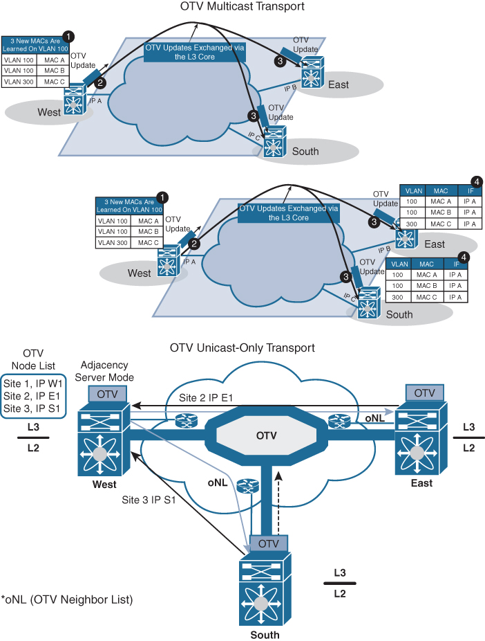
Figure 3-2 OTV Control Plane
![]()
OTV Data Plane Function
After the control plane adjacencies established between the OTV edge devices and MAC address reachability information are exchanged, traffic can start flowing across the overlay. Similar to any L2 Switch, data plane traffic can be
• Unicast traffic
• Multicast traffic
• Broadcast traffic
Unicast Traffic over OTV
In a Layer 2 switch, if PC1 is trying to communicate with PC2 and both belong to the same VLAN, the switch will perform Layer 2 MAC address lookup and forward the traffic to the destination local port. In OTV, an edge device will perform Layer 2 lookup, and the destination will be the remote edge IP address (as shown in Figure 3-3). The OTV edge will encapsulate the Layer 2 packet over Layer 3 and transport it to the OTV remote edge, as shown using the following steps:
Step 1. PC1 starts sending traffic to PC2.
Step 2. When traffic reaches the aggregation layer device (an OTV edge device), a usual Layer 2 lookup is performed to determine how to reach PC2.
Step 3. The MAC table points to a remote OTV edge IP address (in a local switch, MAC points to a local interface).
Step 4. The OTV edge device encapsulates the original Layer 2 frame. The source IP of the outer header is the IP address of its join interface, whereas the destination IP is the IP address of the join interface of the remote edge device. The OTV-encapsulated frame (a regular unicast IP packet) is carried across the transport infrastructure and delivered to the remote OTV edge device.
Step 5. The remote OTV edge device decapsulates the frame, exposing the original Layer 2 packet.
Step 6. The edge device performs another Layer 2 lookup on the original Ethernet frame and discovers that it is reachable through a physical interface, which means it is a MAC address local to the site.
Step 7. The frame is delivered to the MAC destination.
![]()

Figure 3-3 OTV Unicast Data Plane
Given that Ethernet frames are carried across the transport infrastructure after being OTV encapsulated, some considerations around MTU are necessary. In the first implementation, the OTV encapsulation increases the overall MTU size of 42 bytes. This is a result of the operation of the edge device that removes the CRC and the 802.1Q fields from the original Layer 2 frame and adds an OTV Shim (containing the VLAN and Overlay ID information also) and an external IP header.
All OTV control and data plane packets originate from an OTV edge device with the Don’t Fragment (DF) bit set. In a Layer 2 domain, the assumption is that all intermediate LAN segments support at least the configured interface MTU size of the host. This means that mechanisms like Path MTU Discovery (PMTUD) are not an option in this case.
Also, fragmentation and reassembly capabilities are not available on Nexus platforms. Consequently, Cisco recommends increasing the MTU size of all the physical interfaces along the path between the source and destination endpoints to account for introducing the extra 42 bytes by OTV.
Note
This consideration is not OTV specific because the same challenge applies to other Layer 2 VPN technologies, such as EoMPLS or VPLS.
Multicast Traffic over OTV
In certain scenarios, there may be a requirement to establish Layer 2 multicast communication between remote sites. This is the case when a multicast source sending traffic to a specific group is deployed in a given VLAN 10 in site A, whereas multicast receivers belonging to the same VLAN 10 are placed in remote sites B to site N and need to receive traffic for that same group.
Similarly to what is done for the OTV control plane, you need to distinguish the two scenarios where the transport infrastructure is multicast enabled, or not, for the data plane.
For multicast-enabled transport, the Layer 2 multicast traffic must flow across the OTV overlay, and to avoid suboptimal head-end replication, a specific mechanism is required to ensure that multicast capabilities of the transport infrastructure can be leveraged.
The idea is to use a set of source-specific multicast (SSM) groups in the transport to carry these Layer 2 multicast streams. These groups are independent from the ASM group previously introduced to transport the OTV control protocol between sites.
For a unicast-only transporter, when multicast capabilities are not available in the transport infrastructure, Layer 2 multicast traffic can be sent across the OTV overlay by leveraging head-end replication from the OTV device deployed in the DC site where the multicast source is located. However, a specific mechanism based on IGMP snooping is still available to ensure Layer 2 multicast packets are sent only to remote DC sites where active receivers interested in that flow are connected.
Broadcast Traffic over OTV
It is important to highlight that a mechanism is required so that Layer 2 broadcast traffic can be delivered between sites across the OTV overlay. Failure isolation will detail how to limit the amount of broadcast traffic across the transport infrastructure, but some protocols, like Address Resolution Protocol (ARP), would always mandate the delivery of broadcast packets.
In the current OTV software release, when a multicast-enabled transport infrastructure is available, the current NX-OS software release broadcast frames are sent to all remote OTV edge devices by leveraging the same ASM multicast group in the transport already used for the OTV control protocol. Layer 2 broadcast traffic will then be handled exactly the same way as the OTV Hello messages shown in Figure 3-2.
For unicast-only transport infrastructure deployments, head-end replication performed on the OTV device in the site originating the broadcast would ensure traffic delivery to all the remote OTV edge devices that are part of the unicast-only list.
Failure Isolation
One of the main requirements of every LAN extension solution is to provide Layer 2 connectivity between remote sites without giving up the advantages of resiliency, stability, scalability, and so on, obtained by interconnecting sites through a routed transport infrastructure.
OTV achieves this goal by providing four main functions: Spanning Tree Protocol (STP) isolation, unknown unicast traffic suppression, ARP optimization, and broadcast policy control.
STP Isolation
OTV, by default, does not transmit STP bridge protocol data units (BPDUs) across the overlay, as shown in Figure 3-4. This native function does not require the use of an explicit configuration, such as BPDU filtering, and so on. Every site can then become an independent STP domain; STP root configuration, parameters, and the STP protocol flavor can be decided on a per-site basis.
STP isolation fundamentally limits the fate of sharing between data center sites: an STP problem in the control plane of a given site would not produce any effect on the remote data centers.
Limiting the extension of STP across the transport infrastructure potentially creates undetected end-to-end loops that would occur when at least two OTV edge devices are deployed in each site, inviting a common best practice to increase resiliency of the overall solution. Multihoming details how OTV prevents the creation of end-to-end loops without sending STP frames across the OTV overlay.
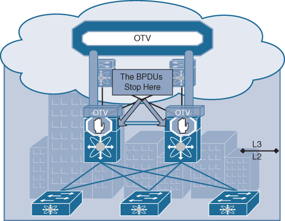
Figure 3-4 STP Isolation
Unknown Unicast Handling
The OTV control protocol will advertise MAC address reachability information between the OTV edge devices and mapping MAC address destinations to IP next hops. The consequence is that the OTV edge device starts behaving like a router instead of a Layer 2 bridge, because it forwards Layer 2 traffic across the overlay if it has previously received information on how to reach that remote MAC destination. Figure 3-5 shows this behavior.
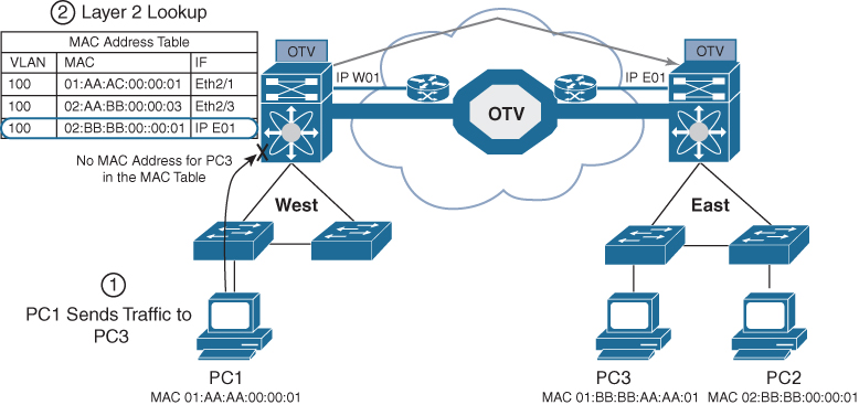
Figure 3-5 Unknown Unicast Traffic
When the OTV edge device receives a frame destined to PC3, it performs the usual Layer 2 lookup in the MAC table. Because it does not have information for the MAC of PC3, Layer 2 traffic is flooded out the internal interfaces, since they behave as regular Ethernet interfaces, but not via the overlay.
Note
This OTV behavior is important to minimize the effects of a server misbehaving and generating streams directed to random MAC addresses. This could occur as a result of a DoS attack as well.
The assumption is that there are no silent or unidirectional devices in the network, so sooner or later the local OTV edge device will learn an address and communicate it to the remaining edge devices through the OTV protocol. To support specific applications, like Microsoft Network Load Balancing Services (NLBS), which require the flooding of Layer 2 traffic to functions, a configuration knob is provided to enable selective flooding. Individual MAC addresses can be statically defined so that Layer 2 traffic destined to them can be flooded across the overlay, or it can be broadcast to all remote OTV edge devices instead of being dropped. The expectation is that this configuration would be required in very specific corner cases so that the default behavior of dropping unknown unicast would be the usual operation model.
ARP Optimization
Another function that reduces the amount of traffic sent across the transport infrastructure is ARP optimization. ARP optimization will reduce the amount of broadcast traffic between sites.
IP ARP is a Layer 2 broadcast frame used to determine the MAC address of the host with a particular IP address. ARP requests are sent across the OTV overlay to all remote sites, with the hope that they will reach the host with that particular IP. The intended host will respond to the originating host’s ARP request using an ARP reply, which will pass via the original OTV edge device that forwarded the ARP request. That OTV edge device will record the ARP reply. OTV edge devices are capable of snooping ARP reply traffic and caching the contained mapping information in a local data table called ARP ND (Neighbor-Discovery). Any subsequent ARP broadcast requests that have a match in the ARP ND will be served from there and will not be sent across the overlay. Figure 3-6 shows an ARP optimization example.
![]()

Figure 3-6 OTV ARP Optimization
One caveat to be aware of is the relation between the MAC aging timer and the ARP cache timer. The ARP cache timer should always be lower than the MAC aging timer; otherwise, traffic might be black-holed, which means incoming or outgoing traffic is silently discarded or dropped. Using the default NX-OS values, and provided the default gateway resides on a Nexus, this should never be an issue with the default set values.
The Nexus defaults for these timers are
• OTV ARP aging timer: 480 seconds / 8 minutes
• MAC aging timer: 1800 seconds / 30 minutes
Broadcast Policy Control
In addition to the previously described ARP optimization, OTV will provide additional functionality, such as broadcast suppression, broadcast white listing, and so on, to reduce the amount of overall Layer 2 broadcast traffic sent across the overlay. Details will be provided upon future functional availability.
![]()
Multihoming OTV
One important function is multihoming where two (or more) OTV edge devices provide LAN extension services to a given site. As mentioned, this redundant node deployment, combined with the fact that STP BPDUs are not sent across the OTV overlay, may lead to the creation of an end-to-end loop, as shown in Figure 3-7.
![]()

Figure 3-7 Creation of an End-to-End STP Loop
The concept of an Authoritative edge device (AED) is introduced to avoid the situation depicted in Figure 3-8. The AED has two main tasks:
1. Forwarding Layer 2 traffic (unicast, multicast and broadcast) between the site and the overlay (and vice versa)
2. Advertising MAC reachability information to the remote edge devices
The AED role is negotiated, on a per-VLAN basis, between all the OTV edge devices belonging to the same site (that is, characterized by the same site identifier, or site ID). OTV uses the site adjacencies as input to determine Authoritative edge devices for the VLANS being extended from the site.
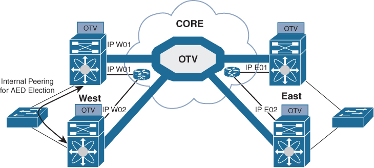
Figure 3-8 Establishment of Internal Peering
The site VLAN should be carried on multiple Layer 2 paths internal to a given site, to increase the resiliency of this internal adjacency (including vPC connections eventually established with other edge switches). However, the mechanism of electing an Authoritative edge device solely based on the communication established on the site VLAN may create situations (resulting from connectivity issues or misconfiguration) where OTV edge devices belonging to the same site can fail to detect one another and thereby end up in an “active/active” mode (for the same data VLAN). This could ultimately result in the creation of a loop scenario.
To address this concern, each OTV device maintains dual adjacencies with other OTV edge devices belonging to the same DC site. OTV edge devices continue to use the site VLAN for discovering and establishing adjacency with other OTV edge devices in a site. This adjacency is called site adjacency.
In addition to the site adjacency, OTV devices also maintain a second adjacency, called overlay adjacency, established via the join interfaces across the Layer 3 network domain. To enable this new functionality, it is now mandatory to configure each OTV device with a site-identifier value. All edge devices that are in the same site must be configured with the same site identifier. This site identifier is advertised in IS-IS hello packets sent over both the overlay as well as on the site VLAN. The combination of the site identifier and the IS-IS system ID is used to identify a neighbor edge device in the same site.
The dual-site adjacency state (and not simply the site adjacency established on the site VLAN) is now used to determine the Authoritative edge device role for each extended data VLAN. All the OTV edge devices can now proactively inform their neighbors in a local site about their capability to become Authoritative edge devices and their forwarding readiness. In other words, if something happens on an OTV device that prevents it from performing its LAN extension functionalities, it can now inform its neighbor about this and let itself be excluded from the AED election process.
An explicit AED capability notification allows the neighbor edge devices to get a fast and reliable indication of failures and to determine AED status accordingly in the consequent AED election, rather than solely depending on the adjacency creation and teardown. The forwarding readiness may change due to local failures, such as the site VLAN or the extended VLANs going down or the join interface going down, or it may be intentional, such as when the edge device is starting up and/or initializing. Hence, the OTV adjacencies may be up, but the OTV device may not be ready to forward traffic. The edge device also triggers a local AED election when its forwarding readiness changes. As a result of its AED capability going down, it will no longer be AED for its VLANs.
The AED capability change received from a neighboring edge device in the same site influences the AED assignment and hence will trigger an AED election. If a neighbor indicates that it is not AED capable, it will not be considered as active in the site. An explicit AED capability down notification received over either the site or the overlay adjacency will bring the neighbor’s dual-site adjacency state down into an inactive state, and the resulting AED election will not assign any VLANs to that neighbor.
The dual-site adjacencies are used to negotiate the Authoritative edge device role. A deterministic algorithm is implemented to split the AED role for odd and even VLANs between two OTV edge devices, as shown in Figure 3-9. More specifically, the edge device identified by a lower system ID will become authoritative for all the even extended VLANs, whereas the device with a higher system ID will “own” the odd extended VLANs.
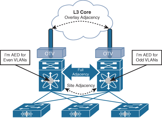
Figure 3-9 OTV AED VLAN Split
FHRP Isolation
One of the important capabilities introduced by OTV is to filter First Hop Redundancy Protocol (FHRP—HSRP, VRRP, and so on) messages across the logical overlay. This is required to allow for the existence of the same default gateway in different locations and optimize the outbound traffic flows (server-to-client direction). Figure 3-10 highlights the root of the problem.
Given that the same VLAN/IP subnet is available in different sites, the free exchange of FHRP messages across the OTV connection would lead to the election of a single default gateway. This would force traffic to follow a suboptimal path to reach the default gateway (in the site where it is deployed) each time it is required to be routed outside the subnet and the server is located in a different site.

Figure 3-10 Suboptimal Outbound Routing
Figure 3-11 shows the deployment of independent default gateways in each data center site, to optimize and localize routing of outbound traffic flows.

Figure 3-11 FHRP Isolation with OTV
It is critical that you enable the filtering of FHRP messages across the overlay because it allows the use of the same FHRP configuration in different sites. The end result is that the same default gateway is available and characterized by the same virtual IP and virtual MAC addresses in each data center. This means that the outbound traffic will be able to follow the optimal and shortest path, always leveraging the local default gateway.
It is important to stress how this outbound path optimization functionality should be deployed in conjunction with an equivalent one optimizing inbound traffic flows to avoid asymmetric traffic behavior (this would be highly undesirable, especially in deployments leveraging stateful services across data centers).
OTV Configurations and Verifications
Table 3-2 lists OTV default parameters. You can alter these parameters as necessary to optimize protocol functionality.
Table 3-2 OTV Default Settings

Table 3-3 covers the NX-OS feature license required for OTV. For more information, visit the Cisco NX-OS Licensing Guide.
Table 3-3 Feature-Based Licenses for Cisco NX-OS OTV

OTV has the following configuration recommendations and limitations:
• If the same device serves as the default gateway in a VLAN interface and the OTV edge device for the VLANs being extended, configure OTV on a device (Nexus 7000 VDC or switch) that is separate from the VLAN interfaces (SVIs).
• The site VLAN must not be extended into the OTV. This configuration is not supported, and this helps to avoid unexpected results.
• When possible, we recommend that you use a separate nondefault Nexus 7000 VDC for OTV to allow for better manageability and maintenance.
• An overlay interface will only be in an up state if the overlay interface configuration is complete and enabled (no shutdown). The join interface has to be in an up state.
• Configure the join interface and all Layer 3 interfaces that face the IP core between the OTV edge devices with the highest maximum transmission unit (MTU) size supported by the IP core. OTV sets the Don’t Fragment (DF) bit in the IP header for all OTV control and data packets so the core cannot fragment these packets.
• Only one join interface can be specified per overlay. You can decide to use one of the following methods:
• Configure a single join interface, which is shared across multiple overlays.
• Configure a different join interface for each overlay, which increases the OTV reliability.
For a higher resiliency, you can use a port channel, but it is not mandatory. There are no requirements for 1-Gigabit Ethernet versus 10-Gigabit Ethernet or dedicated versus shared mode.
• The transport network must support PIM sparse mode (ASM) or PIM-Bidir multicast traffic.
• OTV is compatible with a transport network configured only for IPv4. IPv6 is not supported.
• Do not enable PIM on the join interface.
• ERSPAN ACLs are not supported for use with OTV.
• Ensure the site identifier is configured and is the same for all edge devices on a site. OTV brings down all overlays when a mismatched site identifier is detected from a neighbor edge device and generates a system message.
• You must upgrade all edge devices in the site and configure the site identifier on all edge devices in the site before traffic is restored. An edge device with an older Cisco NX-OS release in the same site can cause traffic loops. You should upgrade all edge devices in the site during the same upgrade window. You do not need to upgrade edge devices in other sites because OTV interoperates between sites with different Cisco NX-OS versions.
• For OTV fast convergence, remote unicast MAC addresses are installed in the OTV Routing Information Base (ORIB), even on non-AED VLANs.
• For OTV fast convergence, even non-AED OTV devices create a delivery source, delivery group (DS,DG) mapping for local multicast sources and send a join request to remote sources if local receivers are available. As a result, there are two remote data groups instead of one for a particular VLAN, source, group (V,S,G) entry.
• One primary IP address and no more than three secondary IP addresses are supported for OTV tunnel depolarization.
Tables 3-4 through 3-7 show some of the most-used OTV configuration commands with their purpose. For full commands, refer to the Nexus Interface Configuration Guide links provided in the “References” section at the end of the chapter.
Table 3-4 OTV Global-Level Commands

Table 3-5 OTV Interface-Level Commands

Table 3-6 OTV Router-Level Commands

Table 3-7 OTV Global-Level Verification Commands

Figure 3-12 shows the OTV network topology with configurations.
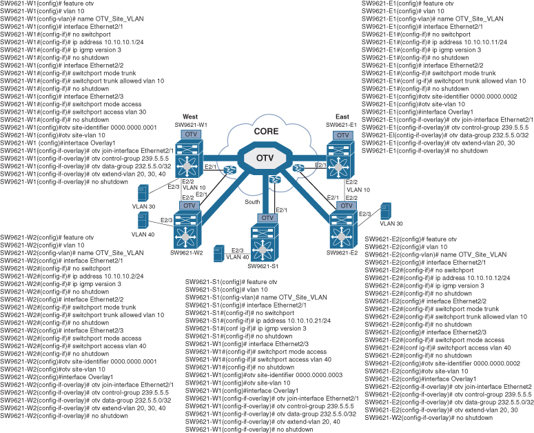
Figure 3-12 OTV Network Topology and Configurations
Example 3-1 shows switch one at the West site (SW9621-W1) with OTV information, neighbor adjacency, IS-IS underlay protocol, and multicast routing.
Example 3-1 SW9621-W1 OTV Results
SW9621-W1# show otv
OTV Overlay Information
Site Identifier 0000.0000.0001
Encapsulation-Format ip - gre
Overlay interface Overlay1
 VPN name            : Overlay1
 VPN state           : UP
 Extended vlans      : 20 30 40 (Total:3)
 Control group       : 239.5.5.5
 Data group range(s) : 232.5.5.0/32
 Broadcast group     : 239.5.5.5
 Join interface(s)   : Eth2/1 (10.10.10.1)
 Site vlan           : 10 (up)
 AED-Capable         : yes
 Capability          : Multicast-Reachable
SW9621-W1# show otv adjacency
Overlay Adjacency database
Overlay-Interface Overlay1  :
Hostname                    System-ID              Dest Addr        Up Time         State
SW9621-E2                   fa16.3e31.f889         10.10.10.12      00:41:40         UP
SW9621-E1                   fa16.3ec3.1f96         10.10.10.11      00:45:20         UP
SW9621-W2                   fa16.3ed2.730a         10.10.10.2       00:55:39         UP
SW9621-S1                   fa16.3ef4.5189         10.10.10.21      01:00:58         UP

SW9621-W1# show otv isis
ISIS process : default
Encap-Type for Multicast mode: GRE
VPN: Overlay1
fwd ready state FALSE
  System ID : fa16.3e56.e725  IS-Type : L1
 Version Number: 3
 Interoperability Flag: 0
  SAP : 439  Queue Handle : 15
  Maximum LSP MTU: 1392
  Graceful Restart enabled. State: Inactive
  Last graceful restart status : none
  Metric-style : advertise(wide), accept(narrow, wide)
  Area address(es) :
    00
  Process is up and running
  VPN ID: 132
  Incremental update routes during SPF run
  Stale routes during non-graceful controlled restart
  Interfaces supported by OTV-IS-IS :
    Overlay1
Level 1
Authentication type and keychain haven't been configured
Authentication check is specified
  Address family IPv4 unicast :
    Number of interface : 1
    Adjacency check disabled
    Distance : 115
    tib-id  : 0
  Address family IPv6 unicast :
    Number of interface : 1
    Adjacency check disabled
    Distance : 115
    tib-id  : 0
  Address family MAC unicast :
    Number of interface : 1
    Adjacency check disabled
    Distance : 115
    tib-id  : 0
  L1 Next SPF: Inactive
AED Server Info:
Capability: 1
Priority: 0
AED Server Elected Value: fa16.3e56.e725
AED State: 0
AED Elected Operational: 4
Backup AED Server Info:
Backup AED Server Elected Value: fa16.3ed2.730a
Backup AED State: 0
Backup AED Elected Operational: 3
SW9621-W1# show ip mroute
IP Multicast Routing Table for VRF “default”

(*, 239.5.5.5/32), uptime: 01:28:26, otv ip
  Incoming interface: Ethernet2/1, RPF nbr: 10.10.10.1
  Outgoing interface list: (count: 1)
    Overlay1, uptime: 01:28:26, otv
Example 3-2 shows switch two at at West site (SW9621-W2) with OTV information.
Example 3-2 SW9621-W2 OTV Results
SW9621-W2# show otv
OTV Overlay Information
Site Identifier 0000.0000.0001
Encapsulation-Format ip - gre
Overlay interface Overlay1
 VPN name            : Overlay1
 VPN state           : UP
 Extended vlans      : 20 30 40 (Total:3)
 Control group       : 239.5.5.5
 Data group range(s) : 232.5.5.0/32
 Broadcast group     : 239.5.5.5
 Join interface(s)   : Eth2/1 (10.10.10.2)
 Site vlan           : 10 (up)
 AED-Capable         : yes
 Capability          : Multicast-Reachable
Example 3-3 shows switch one at the East site (SW9621-E1) with OTV information. Be sure to pay attention to the AED status, which is shown as down, because there is no VLAN active at SW9621-E1.
Example 3-3 SW9621-E1 OTV Results
SW9621-E1# show otv
OTV Overlay Information
Site Identifier 0000.0000.0002
Encapsulation-Format ip - gre

Overlay interface Overlay1

 VPN name            : Overlay1
 VPN state           : UP
 Extended vlans      : 20 30 (Total:2)
 Control group       : 239.5.5.5
 Data group range(s) : 232.5.5.0/32
 Broadcast group     : 239.5.5.5
 Join interface(s)   : Eth2/1 (10.10.10.11)
 Site vlan           : 10 (up)
 AED-Capable         : No (No extended vlan operationally up) <- no active VLAN
 Capability          : Multicast-Reachable
Example 3-4 shows switch two at the East site (SW9621-E2) with OTV information.
Example 3-4 SW9621-E2 OTV Results
SW9621-E2# show otv

OTV Overlay Information
Site Identifier 0000.0000.0002
Encapsulation-Format ip - gre

Overlay interface Overlay1
 VPN name            : Overlay1
 VPN state           : UP
 Extended vlans      : 20 30 (Total:2)
 Control group       : 239.5.5.5
 Data group range(s) : 232.5.5.0/32
 Broadcast group     : 239.5.5.5
 Join interface(s)   : Eth2/3 (10.10.10.12)
 Site vlan           : 10 (up)
 AED-Capable         : Yes
 Capability          : Multicast-Reachable
Example 3-5 shows switch one at the South site (SW9621-S1) with OTV information. Again, be sure to pay attention to the VLAN site and the AED; both are shown as down, because there is a single OTV node at the South site.
Example 3-5 SW9621-S1 OTV Results
SW9621-S1# show otv

OTV Overlay Information
Site Identifier 0000.0000.0003
Encapsulation-Format ip - gre

Overlay interface Overlay1

 VPN name            : Overlay1
 VPN state           : UP
 Extended vlans      : 20 40 (Total:2)
 Control group       : 239.5.5.5
 Data group range(s) : 232.5.5.0/32
 Broadcast group     : 239.5.5.5
 Join interface(s)   : Eth2/1 (10.10.10.21)
 Site vlan           : 10 (down)
 AED-Capable         : No (Site-VLAN is Down)
 Capability          : Multicast-Reachable
Example 3-6 shows connectivity results across the OTV network.
Example 3-6 Connectivity Verifications
VVLAN30-W1# ping 30.0.0.2
Type escape sequence to abort.
Sending 5, 100-byte ICMP Echos to 30.0.0.2, timeout is 2 seconds:
..!!!
Success rate is 60 percent (3/5), round-trip min/avg/max = 1/20/40 ms

VLAN30-W2# Router# ping 30.0.0.2
Type escape sequence to abort.
Sending 5, 100-byte ICMP Echos to 30.0.0.2, timeout is 2 seconds:
!!!!!
Success rate is 100 percent (5/5), round-trip min/avg/max = 1/1/1 ms

VLAN40-W1# Router# ping 40.0.0.2
Type escape sequence to abort.
Sending 5, 100-byte ICMP Echos to 40.0.0.2, timeout is 2 seconds:
..!!!
Success rate is 60 percent (3/5), round-trip min/avg/max = 3/20/40 ms

VLAN40-W2# Router# ping 40.0.0.2
Type escape sequence to abort.
Sending 5, 100-byte ICMP Echos to 40.0.0.2, timeout is 2 seconds:
!!!!!
Success rate is 100 percent (5/5), round-trip min/avg/max = 1/1/3 ms
Virtual Extensible LAN (VXLAN) Overview
VXLAN is an extension to the Layer 2 VLAN. It was designed to provide the same VLAN functionality with greater extensibility and flexibility. VXLAN offers the following benefits:
• VLAN flexibility in multitenant segments: It provides a solution to extend Layer 2 segments over the underlying network infrastructure so that tenant workload can be placed across physical pods in the data center.
• Higher scalability: VXLAN uses a 24-bit segment ID known as the VXLAN network identifier (VNID), which enables up to 16 million VXLAN segments to coexist in the same administrative domain.
• Improved network utilization: VXLAN solved Layer 2 STP limitations. VXLAN packets are transferred through the underlying network based on its Layer 3 header and can take complete advantage of Layer 3 routing, equal-cost multipath (ECMP) routing, and link aggregation protocols to use all available paths.
![]()
VXLAN Encapsulation and Packet Format
VXLAN is a solution to support a flexible, large-scale multitenant environment over a shared common physical infrastructure. The transport protocol over the physical data center network is IP plus UDP.
VXLAN defines a MAC-in-UDP encapsulation scheme where the original Layer 2 frame has a VXLAN header added and is then placed in a UDP-IP packet. With this MAC-in-UDP encapsulation, VXLAN tunnels the Layer 2 network over the Layer 3 network. The VXLAN packet format is shown in Figure 3-13.
![]()

Figure 3-13 VXLAN Packet Format
As shown in Figure 3-13, VXLAN introduces an 8-byte VXLAN header that consists of a 24-bit VNID and a few reserved bits. The VXLAN header together with the original Ethernet frame goes in the UDP payload. The 24-bit VNID is used to identify Layer 2 segments and to maintain Layer 2 isolation between the segments. With all 24 bits in VNID, VXLAN can support 16 million LAN segments.
VXLAN Tunnel Endpoint
VXLAN uses the VXLAN tunnel endpoint (VTEP) to map tenants’ end devices to VXLAN segments and to perform VXLAN encapsulation and decapsulation. Each VTEP function has two interfaces: one is a switch interface on the local LAN segment to support local endpoint communication, and the other is an IP interface to the transport IP network.
Infrastructure VLAN is a unique IP address that identifies the VTEP device on the transport IP network. The VTEP device uses this IP address to encapsulate Ethernet frames and transmits the encapsulated packets to the transport network through the IP interface.
A VTEP device also discovers the remote VTEPs for its VXLAN segments and learns remote MAC Address-to-VTEP mappings through its IP interface. The functional components of VTEPs and the logical topology that is created for Layer 2 connectivity across the transport IP network are shown in Figure 3-14.
![]()

Figure 3-14 VXLAN Tunnel Endpoint (VTEP)
The VXLAN segments are independent of the underlying network topology; conversely, the underlying IP network between VTEPs is independent of the VXLAN overlay. It routes the encapsulated packets based on the outer IP address header, which has the initiating VTEP as the source IP address and the terminating VTEP as the destination IP address.
Virtual Network Identifier
A virtual network identifier (VNI) is a value that identifies a specific virtual network in the data plane. It is typically a 24-bit value part of the VXLAN header, which can support up to 16 million individual network segments. (Valid VNI values are from 4096 to 16,777,215.) There are two main VNI scopes:
• Network-wide scoped VNIs: The same value is used to identify the specific Layer 3 virtual network across all network edge devices. This network scope is useful in environments such as within the data center where networks can be automatically provisioned by central orchestration systems.
Having a uniform VNI per VPN is a simple approach, while also easing network operations (such as troubleshooting). It also means simplified requirements on network edge devices, both physical and virtual devices. A critical requirement for this type of approach is to have a very large number of network identifier values given the network-wide scope.
• Locally assigned VNIs: In an alternative approach supported as per RFC 4364, the identifier has local significance to the network edge device that advertises the route. In this case, the virtual network scale impact is determined on a per-node basis versus a network basis.
When it is locally scoped and uses the same existing semantics as an MPLS VPN label, the same forwarding behaviors as specified in RFC 4364 can be employed. This scope thus allows a seamless stitching together of a VPN that spans both an IP-based network overlay and an MPLS VPN.
This situation can occur, for instance, at the data center edge where the overlay network feeds into an MPLS VPN. In this case, the identifier may be dynamically allocated by the advertising device.
It is important to support both cases and, in doing so, ensure that the scope of the identifier be clear and the values not conflict with each other.
![]()
VXLAN Control Plane
Two widely adopted control planes are used with VXLAN: the VXLAN Flood and Learn Multicast-Based Control Plane and the VXLAN MPBGP EVPN Control Plane.
VXLAN Flood and Learn Multicast-Based Control Plane
Cisco Nexus switches utilize existing Layer 2 flooding mechanisms and dynamic MAC address learning to
• Transport broadcast, unknown unicast, and multicast (BUM) traffic
• Discover remote VTEPs
• Learn remote-host MAC addresses and MAC-to-VTEP mappings for each VXLAN segment
IP multicast is used to reduce the flooding scope of the set of hosts that are participating in the VXLAN segment. Each VXLAN segment, or VNID, is mapped to an IP multicast group in the transport IP network. Each VTEP device is independently configured and joins this multicast group as an IP host through the Internet Group Management Protocol (IGMP). The IGMP joins trigger Protocol Independent Multicast (PIM) joins and signaling through the transport network for the particular multicast group. The multicast distribution tree for this group is built through the transport network based on the locations of participating VTEPs. The multicast tunnel of a VXLAN segment through the underlying IP network is shown in Figure 3-15.
![]()

Figure 3-15 VXLAN Multicast Group in Transport Network
The multicast group shown in Figure 3-16 is used to transmit VXLAN broadcast, unknown unicast, and multicast traffic through the IP network, limiting Layer 2 flooding to those devices that have end systems participating in the same VXLAN segment. VTEPs communicate with one another through the flooded or multicast traffic in this multicast group.
![]()

Figure 3-16 VXLAN Multicast Control Plane
As an example, if End System A wants to talk to End System B, it does the following:
1. End System A generates an ARP request trying to discover the End System B MAC address.
2. When the ARP request arrives at SW1, it will look up its local table, and if an entry is not found, it will encapsulate the ARP request over VXLAN and send it over the multicast group configured for the specific VNI.
3. The multicast RP receives the packet, and it forwards a copy to every VTEP that has joined the multicast group.
4. Each VTEP receives and deencapsulates the packet VXLAN packet and learns the System A MAC address pointing to the remote VTEP address.
5. Each VTEP forwards the ARP request to its local destinations.
6. End System B generates the ARP reply. When SW2 VTEP2 receives it, it looks up its local table and finds an entry with the information that traffic destined to End System A must be sent to VTEP1 address. VTEP2 encapsulates the ARP reply with a VXLAN header and unicasts it to VTEP1.
7. VTEP1 receives and deencapsulates the packet and delivers it to End System A.
8. When the MAC address information is learned, additional packets are fed to the corresponding VTEP address.
VXLAN MPBGP EVPN Control Plane
The EVPN overlay specifies adaptations to the BGP MPLS-based EVPN solution so that it is applied as a network virtualization overlay with VXLAN encapsulation where
• The PE node role described in BGP MPLS EVPN is equivalent to the VTEP/network virtualization edge (NVE) device.
• VTEP information is distributed via BGP.
• VTEPs use control plane learning/distribution via BGP for remote MAC addresses instead of data plane learning.
• Broadcast, unknown unicast, and multicast (BUM) data traffic is sent using a shared multicast tree.
• A BGP route reflector (RR) is used to reduce the full mesh of BGP sessions among VTEPs to a single BGP session between a VTEP and the RR.
• Route filtering and constrained route distribution are used to ensure that the control plane traffic for a given overlay is distributed only to the VTEPs that are in that overlay instance.
• The host (MAC) mobility mechanism ensures that all the VTEPs in the overlay instance know the specific VTEP associated with the MAC.
• Virtual network identifiers (VNIs) are globally unique within the overlay.
The EVPN overlay solution for VXLAN can also be adapted to enable it to be applied as a network virtualization overlay with VXLAN for Layer 3 traffic segmentation. The adaptations for Layer 3 VXLAN are similar to L2 VXLAN, except the following:
• VTEPs use control plane learning/distribution via BGP of IP addresses (instead of MAC addresses).
• The virtual routing and forwarding instances are mapped to the VNI.
• The inner destination MAC address in the VXLAN header does not belong to the host but to the receiving VTEP that does the routing of the VXLAN payload. This MAC address is distributed via the BGP attribute along with EVPN routes.
VXLAN Gateways
VXLAN gateways are used to connect VXLAN and classic VLAN segments to create a common forwarding domain so that tenant devices can reside in both environments. The types of VXLAN gateways are
• Layer 2 Gateway: A Layer 2 VXLAN gateway is a device that encapsulates a classical Ethernet (CE) frame into a VXLAN frame and decapsulates a VXLAN frame into a CE frame. A gateway device transparently provides VXLAN benefits to a device that does not support VXLAN; that device could be a physical host or a virtual machine. The physical hosts or VMs are completely unaware of the VXLAN encapsulation.
• VXLAN Layer 3 Gateway: Similar to traditional routing between different VLANs, a VXLAN router is required for communication between devices that are in different VXLAN segments. The VXLAN router translates frames from one VNI to another. Depending on the source and destination, this process might require decapsulation and reencapsulation of a frame. The Cisco Nexus device supports all combinations of decapsulation, route, and encapsulation. The routing can also be done across native Layer 3 interfaces and VXLAN segments.
You can enable VXLAN routing at the aggregation layer or on Cisco Nexus device aggregation nodes. The spine forwards only IP-based traffic and ignores the encapsulated packets. To help scaling, a few leaf nodes (a pair of border leaves) perform routing between VNIs. A set of VNIs can be grouped into a virtual routing and forwarding (VRF) instance (tenant VRF) to enable routing among those VNIs. If routing must be enabled among a large number of VNIs, you might need to split the VNIs between several VXLAN routers. Each router is responsible for a set of VNIs and a respective subnet. Redundancy is achieved with FHRP.
VXLAN High Availability
For high availability, a pair of virtual port channel (vPC) switches can be used as a logical VTEP device sharing an anycast VTEP address (shown in Figure 3-17).
The vPC switches provide vPCs for redundant host connectivity while individually running Layer 3 protocols with the upstream devices in the underlay network. Both will join the multicast group for the same VXLAN VNI and use the same anycast VTEP address as the source to send VXLAN-encapsulated packets to the devices in the underlay network, including the multicast rendezvous point and the remote VTEP devices. The two vPC VTEP switches appear to be one logical VTEP entity.

Figure 3-17 VXLAN High Availability
vPC peers must have the following identical configurations:
• Consistent mapping of the VLAN to the virtual network segment (VN-segment)
• Consistent NVE binding to the same loopback secondary IP address (anycast VTEP address)
• Consistent VNI-to-group mapping.
For the anycast IP address, vPC VTEP switches must use a secondary IP address on the loopback interface bound to the VXLAN NVE tunnel. The two vPC switches need to have the exact same secondary loopback IP address.
Both devices will advertise this anycast VTEP address on the underlay network so that the upstream devices learn the /32 route from both vPC VTEPs and can load-share VXLAN unicast-encapsulated traffic between them.
In the event of vPC peer-link failure, the vPC operational secondary switch will shut down its loopback interface bound to VXLAN NVE. This shutdown will cause the secondary vPC switch to withdraw the anycast VTEP address from its IGP advertisement so that the upstream devices in the underlay network start to send all traffic just to the primary vPC switch. The purpose of this process is to avoid a vPC active-active situation when the peer link is down. With this mechanism, the orphan devices connected to the secondary vPC switch will not be able to receive VXLAN traffic when the vPC peer link is down.
VXLAN Tenant Routed Multicast
Tenant Routed Multicast (TRM) brings the efficiency of multicast delivery to VXLAN overlays. It is based on standards-based next-gen control plane (ngMVPN) described in IETF RFCs 6513 and 6514. TRM enables the delivery of customer Layer 3 multicast traffic in a multitenant fabric, and this in an efficient and resilient manner.
While BGP EVPN provides a control plane for unicast routing, as shown in Figure 3-18, ngMVPN provides scalable multicast routing functionality. It follows an “always route” approach where every edge device (VTEP) with distributed IP Anycast Gateway for unicast becomes a designated router (DR) for multicast. Bridged multicast forwarding is present only on the edge devices (VTEP) where IGMP snooping optimizes the multicast forwarding to interested receivers. All other multicast traffic beyond local delivery is efficiently routed.

Figure 3-18 Tenant Routed Multicast (TRM)
With TRM enabled, multicast forwarding in the underlay is leveraged to replicate VXLAN-encapsulated routed multicast traffic. A Default Multicast Distribution Tree (Default-MDT) is built per VRF. This is an addition to the existing multicast groups for Layer 2 VNI broadcast, unknown unicast, and Layer 2 multicast replication group. The individual multicast group addresses in the overlay are mapped to the respective underlay multicast address for replication and transport. The advantage of using a BGP-based approach is that TRM can operate as a fully distributed overlay rendezvous point (RP), with the RP presence on every edge device (VTEP).
A multicast-enabled data center fabric is typically part of an overall multicast network. Multicast sources, receivers, and even the multicast rendezvous point might reside inside the data center but might also be inside the campus or externally reachable via the WAN. TRM allows seamless integration with existing multicast networks. It can leverage multicast rendezvous points external to the fabric. Furthermore, TRM allows for tenant-aware external connectivity using Layer 3 physical interfaces or subinterfaces.
VXLAN Configurations and Verifications
VXLAN requires a license. Table 3-8 shows the NX-OS feature license required for VXLAN. For more information, visit the Cisco NX-OS Licensing Guide.
Table 3-8 VXLAN Feature-Based Licenses for Cisco NX-OS

Tables 3-9 through 3-12 show the most-used VXLAN configuration commands along with their purpose. For full commands, refer to the Nexus VXLAN Configuration Guide.
Table 3-9 VXLAN Global-Level Commands

Table 3-10 Interface-Level Commands

Table 3-11 Network Virtual Interface (NVE) Config Commands

Table 3-12 VXLAN Global-Level Verification Commands

Figure 3-19 shows the VXLAN network topology with configurations.

Figure 3-19 VXLAN Control Plane Topology
Example 3-7 shows the spine router (Spine-1 and Spine-2) OSPF and multicast routing configuration, VTEP (VETP-1 and VTEP-2) multicast routing configuration, and multicast routing verification.
Example 3-7 PIM Multicast Configurations and Verifications
Spine-1 Config
Spine-1(config)# feature pim
Spine-1(config)# interface loopback1
Spine-1(config-if)# ip address 192.168.0.100/32
Spine-1(config-if)# ip pim sparse-mode
Spine-1(config-if)# ip router ospf 1 area 0.0.0.0
Spine-1(config)# ip pim rp-address 192.168.0.100
Spine-1(config)# ip pim anycast-rp 192.168.0.100 192.168.0.6
Spine-1(config)# ip pim anycast-rp 192.168.0.100 192.168.0.7
Spine-1(config)# interface E1/1
Spine-1(config-if)# ip pim sparse-mode
Spine-1(config)# interface E1/2
Spine-1(config-if)# ip pim sparse-mode
Spine-1(config)# interface E1/3
Spine-1(config-if)# ip pim sparse-mode
Spine-1(config)# interface loopback0
Spine-1(config-if)# ip pim sparse-mode
Spine-2 Config (PIM Redundancy)
Spine-2(config)# feature pim
Spine-2(config)# interface loopback1
Spine-2(config-if)# ip address 192.168.0.100/32
Spine-2(config-if)# ip pim sparse-mode
Spine-2(config-if)# ip router ospf 1 area 0.0.0.0
Spine-2(config)# ip pim rp-address 192.168.0.100
Spine-2(config)# ip pim anycast-rp 192.168.0.100 192.168.0.6
Spine-2(config)# ip pim anycast-rp 192.168.0.100 192.168.0.7
Spine-2(config)# interface E1/1
Spine-2(config-if)# ip pim sparse-mode
Spine-2(config)# interface E1/2
Spine-2(config-if)# ip pim sparse-mode
Spine-2(config)# interface E1/3
Spine-2(config-if)# ip pim sparse-mode
Spine-2(config)# interface loopback0
Spine-2(config-if)# ip pim sparse-mode
VTEP-1 PIM Config
VTEP-1(config)# feature pim
VTEP-1(config)# ip pim rp-address 192.168.0.100
VTEP-1 (config)# interface E1/1
VTEP-1 (config-if)# ip pim sparse-mode
VTEP-1 (config)# interface E1/2
VTEP-1 (config-if)# ip pim sparse-mode
VTEP-1 (config)# interface loopback0
VTEP-1 (config-if)# ip pim sparse-mode
VTEP-1 (config)# interface loopback1
VTEP-1 (config-if)# ip pim sparse-mode
VTEP-3 PIM Config
VTEP-3(config)# feature pim
VTEP-3(config)# ip pim rp-address 192.168.0.100
VTEP-3(config)# interface E1/1
VTEP-3(config-if)# ip pim sparse-mode
VTEP-3(config)# interface E1/2
VTEP-3(config-if)# ip pim sparse-mode
VTEP-3(config)# interface loopback0
VTEP-3(config-if)# ip pim sparse-mode
VTEP-3(config)# interface loopback1
VTEP-3(config-if)# ip pim sparse-mode
Spine 1 Verifications
Spine-1# show ip pim neighbor
PIM Neighbor Status for VRF “default”
Neighbor         Interface         Uptime   Expires       DR        Bidir-   BFD
                                                          Priority  Capable  State
10.0.0.22        Ethernet1/1      00:02:21 00:01:23         1        yes      n/a
10.0.0.26        Ethernet1/2      00:01:50 00:01:20         1        yes      n/a
10.0.0.30        Ethernet1/3      00:00:37 00:01:38         1        yes      n/a
Spine-1# show ip pim rp
PIM RP Status Information for VRF “default”
BSR disabled
Auto-RP disabled
BSR RP Candidate policy: None
BSR RP policy: None
Auto-RP Announce policy: None
Auto-RP Discovery policy: None
Anycast-RP 192.168.0.100 members:
  192.168.0.6*  192.168.0.7
RP: 192.168.0.100*, (0),
 uptime: 00:04:29   priority: 255,
 RP-source: (local),
 group ranges:
 224.0.0.0/4
Spine 2 Verifications
Spine-2# show ip pim neighbor
PIM Neighbor Status for VRF “default”
Neighbor         Interface        Uptime   Expires        DR        Bidir-    BFD
                                                          Priority  Capable   State
10.0.128.6       Ethernet1/1      00:02:21 00:01:23        1         yes       n/a
10.0.128.10      Ethernet1/2      00:01:50 00:01:20        1         yes       n/a
10.0.128.14      Ethernet1/3      00:00:37 00:01:38        1         yes       n/a
Spine-2# show ip pim rp
PIM RP Status Information for VRF “default”
BSR disabled
Auto-RP disabled
BSR RP Candidate policy: None
BSR RP policy: None
Auto-RP Announce policy: None
Auto-RP Discovery policy: None
Anycast-RP 192.168.0.100 members:
  192.168.0.6  192.168.0.7*
RP: 192.168.0.100*, (0),
 uptime: 00:04:16   priority: 255,
 RP-source: (local),
 group ranges:
 224.0.0.0/4
VTEP-1 Verifications
VTEP-1# show ip pim neighbor
PIM Neighbor Status for VRF “default”
Neighbor         Interface           Uptime    Expires   DR       Bidir-        BFD
                                                         Priority Capable       State
10.0.0.21        Ethernet1/1         00:03:47  00:01:32   1        yes            n/a
10.0.128.5       Ethernet1/2         00:03:46  00:01:37   1        yes            n/a
VTEP-1# show ip pim rp
PIM RP Status Information for VRF “default”
BSR disabled
Auto-RP disabled
BSR RP Candidate policy: None
BSR RP policy: None
Auto-RP Announce policy: None
Auto-RP Discovery policy: None
RP: 192.168.0.100, (0),
 uptime: 00:03:53   priority: 255,
 RP-source: (local),
 group ranges:
 224.0.0.0/4
VTEP-3 Verifications
VTEP-3# show ip pim neighbor
PIM Neighbor Status for VRF “default”
Neighbor        Interface            Uptime    Expires   DR       Bidir-        BFD
                                                         Priority Capable       State
10.0.0.21       Ethernet1/1         00:03:47  00:21:32   1        yes            n/a
10.0.128.5      Ethernet1/2         00:03:46  00:03:37   1        yes            n/a
VTEP-3# show ip pim rp
PIM Neighbor Status for VRF “default”
Neighbor        Interface            Uptime    Expires   DR       Bidir-  BFD
                                                         Priority Capable State
10.0.0.29       Ethernet1/1          00:03:06  00:01:21  1        yes     n/a
10.0.128.13     Ethernet1/2          00:02:48  00:01:35  1        yes     n/a
Leaf-3(config)# show ip pim rp
PIM RP Status Information for VRF “default”
BSR disabled
Auto-RP disabled
BSR RP Candidate policy: None
BSR RP policy: None
Auto-RP Announce policy: None
Auto-RP Discovery policy: None
RP: 192.168.0.100, (0),
 uptime: 00:03:11   priority: 255,
 RP-source: (local),
 group ranges:
 224.0.0.0/4
Example 3-8 shows the VTEP (VETP-1 and VTEP-2) VXLAN and VXLAN Network Virtual Interface (NVE) configuration and status verification.
Example 3-8 VXLAN Configurations and Verifications
VTEP-1 Config
VTEP-1(config)# feature vn-segment-vlan-based
VTEP-1(config)# feature vn overlay
VTEP-1(config)# vlan 10
VTEP-1(config-vlan)# vn-segment 160010
VTEP-1(config)# vlan 20
VTEP-1(config-vlan)# vn-segment 160020
VTEP-1(config)# interface nve1
VTEP-1 (config-if)# source-interface loopback1
VTEP-1 (config-if)# member vni 160010 mcast-group 231.1.1.1
VTEP-1 (config-if)# member vni 160020 mcast-group 231.1.1.1
VTEP-1 (config-if)# no shutdown
VTEP-3 Config
VTEP-3(config)# feature vn-segment-vlan-based
VTEP-3(config)# feature vn overlay
VTEP-3(config)# vlan 10
VTEP-3(config-vlan)# vn-segment 160010
VTEP-3(config)# vlan 20
VTEP-3(config-vlan)# vn-segment 160020
VTEP-3(config)# interface nve1
VTEP-3(config-if)# source-interface loopback1
VTEP-3(config-if)# member vni 160010 mcast-group 231.1.1.1
VTEP-3(config-if)# member vni 160020 mcast-group 231.1.1.1
VTEP-3(config-if)# no shutdown
VTEP-1 Verifications
VTEP-1# show nve vni
Codes: CP - Control Plane        DP - Data Plane
       UC - Unconfigured         SA - Suppress ARP
       SU - Suppress Unknown Unicast
Interface VNI      Multicast-group   State Mode Type [BD/VRF]      Flags
--------- -------- ----------------- ----- ---- ------------------ -----
nve1      160010   231.1.1.1         Up    DP   L2    [10]
nve1      160020   231.1.1.1         Up    DP   L2    [20]
VTEP-1# show vxlan
Vlan            VN-Segment
====            ==========
10              160010
20              160020
VTEP-1# ping 10.10.10.3
PING 10.10.10.3 (10.10.10.3) : 56 data bytes
64 bytes from 10.10.10.3: icmp_seq=0 ttl=254 time=8.114 ms
64 bytes from 10.10.10.3: icmp_seq=1 ttl=254 time=5.641 ms
64 bytes from 10.10.10.3: icmp_seq=2 ttl=254 time=6.213 ms
64 bytes from 10.10.10.3: icmp_seq=3 ttl=254 time=6.119 ms
VTEP-1# show nve peers
Interface Peer-IP            State LearnType Uptime   Router-Mac
--------- ---------------  ----- --------- -------- -----------------
nve1      192.168.0.110     Up    DP        00:09:08      n/a
VTEP-1# show ip mroute
IP Multicast Routing Table for VRF “default”
(*, 231.1.1.1/32), uptime: 00:10:38, nve ip pim
  Incoming interface: Ethernet1/1, RPF nbr: 10.0.0.29
  Outgoing interface list: (count: 1)
    nve1, uptime: 00:10:38, nve
(192.168.0.18/32, 231.1.1.1/32), uptime: 00:02:34, ip mrib pim
  Incoming interface: Ethernet1/2, RPF nbr: 10.0.128.13
  Outgoing interface list: (count: 1)
    nve1, uptime: 00:02:34, mrib
(*, 232.0.0.0/8), uptime: 00:17:03, pim ip
  Incoming interface: Null, RPF nbr: 0.0.0.0
  Outgoing interface list: (count: 0)
VTEP-3 Verifications
VTEP-3# show nve vni
Codes: CP - Control Plane        DP - Data Plane
       UC - Unconfigured         SA - Suppress ARP
       SU - Suppress Unknown Unicast
Interface VNI      Multicast-group   State Mode Type [BD/VRF]      Flags
--------- -------- ----------------- ----- ---- ------------------ -----
nve1      160010   231.1.1.1         Up    DP   L2    [10]
nve1      160020   231.1.1.1         Up    DP   L2    [20]
VTEP-3# show vxlan
Vlan            VN-Segment
====            ==========
10              160010
20              160020
VTEP-3# ping 10.10.10.1
PING 10.10.10.1 (10.10.10.1) : 56 data bytes
64 bytes from 10.10.10.1: icmp_seq=0 ttl=254 time=7.212 ms
64 bytes from 10.10.10.1: icmp_seq=1 ttl=254 time=6.243 ms
64 bytes from 10.10.10.1: icmp_seq=2 ttl=254 time=5.268 ms
64 bytes from 10.10.10.1: icmp_seq=3 ttl=254 time=6.397 ms
VTEP-1# show nve peers
Interface Peer-IP            State LearnType Uptime   Router-Mac
--------- ---------------  ----- --------- -------- -----------------
nve1      192.168.0.18    Up    DP        00:09:08      n/a
VTEP-3# show ip mroute
IP Multicast Routing Table for VRF “default”
(*, 231.1.1.1/32), uptime: 00:10:38, nve ip pim
  Incoming interface: Ethernet1/1, RPF nbr: 10.0.0.29
  Outgoing interface list: (count: 1)
    nve1, uptime: 00:10:38, nve
(192.168.0.18/32, 231.1.1.1/32), uptime: 00:02:34, ip mrib pim
  Incoming interface: Ethernet1/2, RPF nbr: 10.0.128.13
  Outgoing interface list: (count: 1)
    nve1, uptime: 00:02:34, mrib
(192.168.0.110/32, 231.1.1.1/32), uptime: 00:10:38, nve mrib ip pim
  Incoming interface: loopback1, RPF nbr: 192.168.0.110
  Outgoing interface list: (count: 1)
    Ethernet1/2, uptime: 00:09:39, pim
(*, 232.0.0.0/8), uptime: 00:17:03, pim ip
  Incoming interface: Null, RPF nbr: 0.0.0.0
  Outgoing interface list: (count: 0)
Exam Preparation Tasks
As mentioned in the section “How to Use This Book” in the Introduction, you have a couple of choices for exam preparation: the exercises here, Chapter 20, “Final Preparation,” and the exam simulation questions in the Pearson Test Prep software online.
Review All Key Topics
Review the most important topics in the chapter, noted with the key topic icon in the outer margin of the page. Table 3-13 lists a reference to these key topics and the page numbers on which each is found.
![]()
Table 3-13 Key Topics for Chapter 3

The system does not form the vPC peer link until you configure a vPC
Define Key Terms
Define the following key terms from this chapter, and check your answers in the Glossary.
virtual private network (VPN)
any-source multicast (ASM)
source-specific multicast (SSM)
cyclic redundancy check (CRC)
Path MTU Discovery (PMTUD)
Network Load Balancing Services (NLBS)
broadcast unknown unicast and multicast (BUM)
Internet Group Management Protocol (IGMP)
Protocol Independent Multicast (PIM)
Ethernet VPN (EVPN)
Spanning Tree Protocol (STP)
bridge protocol data units (BPDUs)
Media Access Control (MAC)
local-area network (LAN)
wide-area network (WAN)
virtual LAN (VLAN)
User Datagram Protocol (UDP)
Internet Protocol (IP)
virtual port channels (vPCs)
Hot Standby Router Protocol (HSRP)
virtual routing and forwarding (VRF)
virtual device contexts (VDC)
equal-cost multipath (ECMP)
maximum transmission unit (MTU)
Address Resolution Protocol (ARP)
Cisco NX-OS
Cisco Nexus
References
Overlay Transport Virtualization (OTV): https://www.cisco.com/c/en/us/solutions/data-center-virtualization/overlay-transport-virtualization-otv/index.html
Cisco Overlay Transport Virtualization Technology Introduction and Deployment Considerations: https://www.cisco.com/c/en/us/td/docs/solutions/Enterprise/Data_Center/DCI/whitepaper/DCI3_OTV_Intro.pdf
Cisco Nexus 7000 Series NX-OS OTV Configuration Guide, Release 8.0(x): https://www.cisco.com/c/en/us/td/docs/switches/datacenter/nexus7000/sw/otv/config/cisco_nexus7000_otv_config_guide_8x.html
Cisco Nexus 9000 Series NX-OS VXLAN Configuration Guide, Release 9.3(x): https://www.cisco.com/c/en/us/td/docs/switches/datacenter/nexus9000/sw/93x/vxlan/configuration/guide/b-cisco-nexus-9000-series-nx-os-vxlan-configuration-guide-93x.html
Cisco Nexus 7000 Series NX-OS VXLAN Configuration Guide, Release 8.0(x): https://www.cisco.com/c/en/us/td/docs/switches/datacenter/nexus7000/sw/vxlan/config/cisco_nexus7000_vxlan_config_guide_8x.html
Configure VXLAN: https://www.cisco.com/c/en/us/support/docs/switches/nexus-9000-series-switches/118978-config-vxlan-00.html
Cisco Live Design and Implementation of DCI Network BRKDCN-2657: https://www.ciscolive.com/c/dam/r/ciscolive/emea/docs/2018/pdf/BRKDCN-2657.pdf
A Summary of Cisco VXLAN Control Planes: Multicast, Unicast, MP-BGP EVPN: https://blogs.cisco.com/perspectives/a-summary-of-cisco-vxlan-control-planes-multicast-unicast-mp-bgp-evpn-2