
Chapter 11. Cisco Unified Computing Systems Overview
The Cisco Unified Computing System (UCS) is the industry’s first converged data center platform. The Cisco UCS delivers smart, programmable infrastructure that simplifies and speeds enterprise-class applications and service deployment in bare-metal, virtualized, and cloud-computing environments.
The Cisco UCS is an integrated computing infrastructure with intent-based management to automate and accelerate deployment of all applications, including virtualization and cloud computing, scale-out and bare-metal workloads, and in-memory analytics, in addition to edge computing that supports remote and branch locations and massive amounts of data from the Internet of Things (IoT).
This chapter covers the following key topics:
• Cisco UCS Architecture: This section provides an overview of UCS B-Series, C-Series, and Fabric Interconnect (FI) architecture and connectivity.
• Cisco UCS Initial Setup and Management: This section cover UCS B-Series and C-Series initial setup and configuration.
• Network Management: This section discusses UCS LAN management, including VLANs, pools, polices, quality of service (QoS), and templates.
• UCS Storage Management: This section discusses UCS SAN management, including SAN connectivity (iSCSI, Fiber Channel, FCoE), VSANs, WWN pools, and zoning.
“Do I Know This Already?” Quiz
The “Do I Know This Already?” quiz enables you to assess whether you should read this entire chapter thoroughly or jump to the “Exam Preparation Tasks” section. If you are in doubt about your answers to these questions or your own assessment of your knowledge of the topics, read the entire chapter. Table 11-1 lists the major headings in this chapter and their corresponding “Do I Know This Already?” quiz questions. You can find the answers in Appendix A, “Answers to the ‘Do I Know This Already?’ Quizzes.”
Table 11-1 “Do I Know This Already?” Section-to-Question Mapping”

Caution
The goal of self-assessment is to gauge your mastery of the topics in this chapter. If you do not know the answer to a question or are only partially sure of the answer, you should mark that question as wrong for purposes of the self-assessment. Giving yourself credit for an answer you correctly guess skews your self-assessment results and might provide you with a false sense of security.
1. What are the Cisco UCS Mini main infrastructure components? (Choose two answers.)
a. Fabric Interconnect
b. Blade Server
c. Power Supply
d. I/O module
2. What type of connection does UCS blade chassis FEX fabric support? (Choose two answers.)
a. Basic mode
b. Discrete mode
c. Port mode
d. Port channel mode
3. When a host firmware package policy is created, what must it be associated with to upgrade the BIOS?
a. Blade or blade pool
b. Boot policy
c. Service profile
d. Service template
4. Which commands allow you to view the state of high availability between the two clustered fabric interconnects? (Choose two answers.)
a. show cluster HA status
b. show cluster state extended
c. show cluster extended-state
d. show cluster state
5. What is the correct path to verify the overall status of Chassis 1 | Server 3?
a. Servers tab > Chassis > Server 3 General tab
b. Status tab > Chassis > Chassis 1 > Servers > Server 3
c. Equipment tab > Chassis > Chassis 1 > Servers > Server 3 FSM tab
d. Equipment tab > Chassis > Chassis 1 > Servers > Server 3 Status tab
e. Admin tab > Chassis > Chassis 1 > Servers > Server 3 General tab
f. Equipment tab > Chassis > Chassis 1 > Servers > Server 3 General tab
6. If the virtual local-area network (VLAN) is deleted from the fabric interconnect using the Cisco UCS Manager, what happens?
a. The port belonging to the VLAN is assigned to the default VLAN.
b. The port belonging to the VLAN is pinned to a native VLAN.
c. You cannot delete the VLAN because an interface member belongs to that VLAN.
d. The port changes to a shutdown state.
7. Which of the following characteristics are true in the Cisco UCS unicast traffic path in end-host switching mode? (Choose two answers.)
a. Each server link is pinned as one-to-many uplink ports.
b. Server-to-server Layer 2 traffic is pinned to an uplink port.
c. Server-to-network traffic goes out on its pinned uplink port.
d. Server-to-server Layer 2 traffic is locally switched.
e. Server-to-network traffic is locally switched.
8. Which method is a TCP/IP-based protocol for establishing and managing connections between IP-based storage devices, hosts, and clients?
a. iFCP
b. FCIP
c. iSCSI
d. FCoE
9. Which important feature on the front end is provided to clients by multiple servers that access the same storage devices across a storage-area network?
a. Security
b. Storage
c. Redundancy
d. Recovery
Foundation Topics
Cisco UCS Architecture
The Cisco Unified Computing System (UCS) has a unique architecture that integrates compute, data network access, and storage network access into a common set of components under a single management portal (single-pane-of-glass portal). The Cisco UCS combines access layer networking and servers. This high-performance, next-generation server system provides a data center with a high degree of workload agility and scalability. The hardware and software components support Cisco’s unified fabric, which runs multiple types of data center traffic over a single converged network adapter. Figure 11-1 shows UCS management and network connectivity.
![]()

Figure 11-1 Cisco Unified Computing System Architecture
The simplified architecture of the Cisco UCS reduces the number of required devices and centralizes switching resources. By eliminating switching inside a chassis, Cisco significantly reduced the network access layer fragmentation. The Cisco UCS implements a Cisco unified fabric within racks and groups of racks, supporting Ethernet and Fibre Channel protocols. This simplification reduces the number of switches, cables, adapters, and management points by up to two-thirds. All devices in a Cisco UCS domain remain under a single management domain, which remains highly available through the use of redundant components. The Cisco UCS architecture provides the following features (see Figure 11-2):
• High availability: The management and data plane of the Cisco UCS is designed for high availability and redundant access layer fabric interconnects. In addition, the Cisco UCS supports existing high-availability and disaster recovery solutions for the data center, such as data replication and application-level clustering technologies.
• Scalability: A single Cisco UCS domain supports multiple chassis and their servers, all of which are administered through one Cisco UCS Manager.
• Flexibility: A Cisco UCS domain allows you to quickly align computing resources in the data center with rapidly changing business requirements. This built-in flexibility is determined by whether you choose to fully implement the stateless computing feature. Pools of servers and other system resources can be applied as necessary to respond to workload fluctuations, support new applications, scale existing software and business services, and accommodate both scheduled and unscheduled downtime. Server identity can be abstracted into a mobile service profile that can be moved from server to server with minimal downtime and no need for additional network configuration. With this level of flexibility, you can quickly and easily scale server capacity without having to change the server identity or reconfigure the server, LAN, or SAN. During a maintenance window, you can quickly do the following:
• Deploy new servers to meet unexpected workload demand and rebalance resources and traffic.
• Shut down an application, such as a database management system, on one server and then boot it up again on another server with increased I/O capacity and memory resources.
• Optimized for server virtualization: The Cisco UCS has been optimized to implement VM-FEX technology. This technology provides improved support for server virtualization, including better policy-based configuration and security, conformance with a company’s operational model, and accommodation for VMware’s VMotion.
![]()
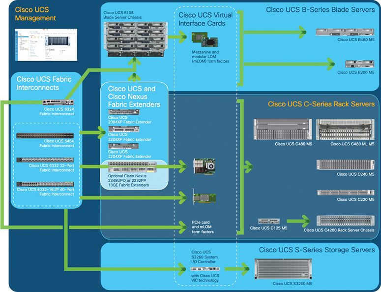
Figure 11-2 Cisco UCS Components and Connectivity
![]()
Cisco UCS Components and Connectivity
The main components of the Cisco UCS are as follows:
• Cisco UCS Manager: The Cisco UCS Manager is the centralized management interface for the Cisco UCS.
• Cisco UCS Fabric Interconnects: The Cisco UCS Fabric Interconnect is the core component of Cisco UCS deployments, providing both network connectivity and management capabilities for the Cisco UCS system. The Cisco UCS Fabric Interconnects run the Cisco UCS Manager control software and consist of the following components:
• Cisco UCS 6200 Series Fabric Interconnects, Cisco UCS 6332 Series Fabric Interconnects, and Cisco UCS Mini
• Transceivers for network and storage connectivity
• Expansion modules for the various Fabric Interconnects
• Cisco UCS Manager software
• Cisco UCS I/O modules and Cisco UCS Fabric Extender: I/O modules (or IOMs) are also known as Cisco Fabric Extenders (FEXs) or simply FEX modules. These modules serve as line cards to the FIs in the same way that Nexus series switches can have remote line cards. I/O modules also provide interface connections to blade servers. They multiplex data from blade servers and provide this data to FIs and do the same in the reverse direction. In production environments, I/O modules are always used in pairs to provide redundancy and failover.
Note
The 40G backplane setting is not applicable for 22xx IOMs.
• Cisco UCS blade server chassis: The Cisco UCS 5100 Series Blade Server Chassis is a crucial building block of the Cisco UCS, delivering a scalable and flexible architecture for current and future data center needs, while helping reduce total cost of ownership.
• Cisco UCS blade servers: Cisco UCS blade servers are at the heart of the Cisco UCS solution. They come in various system resource configurations in terms of CPU, memory, and hard disk capacity. All blade servers are based on Intel Xeon processors. There is no AMD option available.
• Cisco UCS rack servers: The Cisco UCS rack-mount servers are standalone servers that can be installed and controlled individually. Cisco provides FEXs for the rack-mount servers. FEXs can be used to connect and manage rack-mount servers from FIs. Rack-mount servers can also be directly attached to the fabric interconnect. Small and medium businesses (SMBs) can choose from different blade configurations as per business needs.
• Cisco UCS S-Series: Storage servers are modular servers that support up to 60 large-form-factor internal drives to support storage-intensive workloads including big data, content streaming, online backup, and storage-as-a-service applications. The servers support one or two computing nodes with up to two CPUs each, and with up 160 Gbps of unified fabric connectivity per node. These features simplify the process of deploying just the right amount of resources to most efficiently support your applications.
• Cisco UCS Mini solutions: These solutions can be created by using Cisco UCS 6234 Fabric Interconnects in the blade server chassis instead of rack-mount FEXs. This creates a standalone Cisco UCS instance that can connect to blade servers, rack servers, and external storage systems.
Cisco UCS 5108 Blade Server Chassis
The Cisco UCS 5108 Blade Server Chassis is six rack units (6RU) high, can mount in an industry-standard 19-inch rack, and uses standard front-to-back cooling (see Figure 11-3). A chassis can accommodate up to eight half-width or four full-width Cisco UCS B-Series blade servers form factors within the same chassis. By incorporating unified fabric and fabric-extender technology, the Cisco Unified Computing System enables the chassis to
• Have fewer physical components.
• Require no independent management.
• Be more energy efficient than a traditional blade server chassis.
The Cisco UCS 5108 Blade Server Chassis is supported with all generations of fabric interconnects.

Figure 11-3 UCS 5108 Blade Server Chassis
UCS Blade Servers
Cisco UCS B-Series blade servers are based on Intel Xeon processors (see Figure 11-4). They work with virtualized and nonvirtualized applications to increase performance, energy efficiency, flexibility, and administrator productivity.
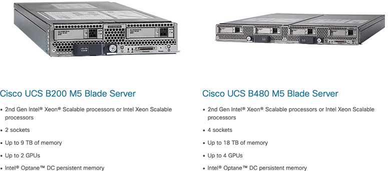
Figure 11-4 UCS B200 M5 and B480 M5 Blade Servers
With the Cisco UCS blade server, you can quickly deploy stateless physical and virtual workloads, with the programmability that the Cisco UCS Manager and Cisco Single Connect technology enables.
Cisco UCS B480 M5 is a full-width server that uses second-generation Intel Xeon Scalable processors or Intel Xeon Scalable processors with up to 6 TB of memory or 12 TB of Intel Optane DC persistent memory; up to four SAS, SATA, and NVMe drives; M.2 storage; up to four GPUs; and 160-Gigabit Ethernet connectivity. It offers exceptional levels of performance, flexibility, and I/O throughput to run the most demanding applications.
Cisco UCS B200 M5 is a half-width server that uses second-generation Intel Xeon Scalable processors or Intel Xeon Scalable processors with up to 3 TB of memory or 6 TB of Intel Optane DC persistent memory; up to two SAS, SATA, and NVMe drives; plus M.2 storage; up to two GPUs; and up to 80-Gigabit Ethernet. The Cisco UCS B200 M5 blade server offers exceptional levels of performance, flexibility, and I/O throughput to run applications.
Note
The central processing unit (CPU) is designed to control all computer parts, improve performance, and support parallel processing. The current CPU is a multicore processor. A graphic processing unit (GPU) is used in computer graphic cards and image processing. The GPU can be used as a coprocessor to accelerate CPUs. In today’s IT world, distributed applications (such as artificial intelligence, or AI) or deep learning applications require high-speed and parallel processing. GPUs are the best solution for distributed applications because GPUs contain high-core density (256 cores or more) compared to CPUs that contain 8 or 16 or a maximum of 32 cores. CPUs can offload some of the compute-intensive and time-consuming portions of the code to the GPU.
Cisco UCS Rack Servers
UCS C-Series rack servers deliver unified computing in an industry-standard form factor to increase agility (see Figure 11-5). Each server addresses varying workload challenges through a balance of processing, memory, I/O, and internal storage resources.

Figure 11-5 UCS C-Series Rack Servers
Cisco UCS Storage Servers
The Cisco UCS S3260 storage server is a modular dual-node x86 server designed for investment protection (see Figure 11-6). Its architectural flexibility provides high performance or high capacity for your data-intensive workloads. Using a storage server combined with the Cisco UCS Manager, you can easily deploy storage capacity from terabytes to petabytes within minutes.
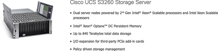
Figure 11-6 Cisco UCS Storage Server
The Cisco UCS S3260 helps you achieve the highest levels of performance and capacity. With a dual-node capability that is based on the Intel Xeon Scalable processors or Intel Xeon processor E5-2600 v4 series, it features up to 720 TB of local storage in a compact 4-rack-unit (4RU) form factor. The drives can be configured with enterprise-class Redundant Array of Independent Disks (RAID) redundancy or as “just a bunch of disks” (JBOD) in pass-through mode. Network connectivity is provided with dual-port 40G per server nodes with expanded unified I/O capabilities for connectivity between NAS and SAN environments. This high-capacity storage server comfortably fits in a standard 32-inch depth rack, such as the Cisco R42612 rack.
![]()
Cisco UCS Mini
The Cisco UCS Mini solution extends the Cisco UCS architecture into environments that requires smaller domains, including branch and remote offices, point-of-sale locations, and smaller IT environments.
The Cisco UCS Mini has three main infrastructure components:
• Cisco UCS 6324 Fabric Interconnect
• Cisco UCS blade server chassis
• Cisco UCS blade or rack-mount servers
In the Cisco UCS Mini solution, the Cisco UCS 6324 Fabric Interconnect is collapsed into the I/O module form factor and is inserted into the IOM slot of the blade server chassis. The Cisco UCS 6324 Fabric Interconnect has 24 × 10G ports available on it. Sixteen of these ports are server facing, and two 10G ports are dedicated to each of the eight half-width blade slots. The remaining eight ports are divided into groups of four 1/10G Enhanced Small Form-Factor Pluggable (SFP+) ports and one 40G Quad Small Form-Factor Pluggable (QSFP) port, which is called the scalability port. Figure 11-7 shows UCS Mini connectivity.
Note
Currently, the Cisco UCS Manager supports only one extended chassis for the Cisco UCS Mini.
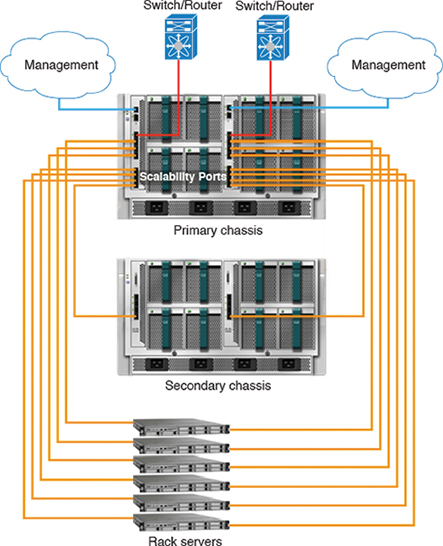
Figure 11-7 The Cisco UCS Mini Infrastructure
Cisco UCS Fabric Infrastructure
Cisco UCS Fabric Interconnects are top-of-rack devices and provide unified access to the Cisco UCS domain. The Cisco UCS Fabric Interconnect hardware is now in its fourth generation. The following fabric interconnects are available in the Cisco UCS Fabric Interconnects product family:
• Cisco UCS 6454 Fabric Interconnects
• Cisco UCS 6300 Series Fabric Interconnects
• Cisco UCS 6200 Series Fabric Interconnects
• Cisco UCS 6324 Fabric Interconnects
The Cisco UCS 6200 Series supports expansion modules that can be used to increase the number of 10G, Fibre Channel over Ethernet (FCoE), and Fibre Channel ports:
• The Cisco UCS 6248 UP has 32 ports on the base system. It can be upgraded with one expansion module providing an additional 16 ports.
• The Cisco UCS 6296 UP has 48 ports on the base system. It can be upgraded with three expansion modules providing an additional 48 ports.
Cisco UCS 6454 Fabric Interconnect
The Cisco UCS 6454 Fabric Interconnect provides both network connectivity and management capabilities to the Cisco UCS system. The fabric interconnect provides Ethernet and Fibre Channel to the servers in the system. The servers connect to the fabric interconnect and then to the LAN or SAN.
Each Cisco UCS 6454 Fabric Interconnect runs the Cisco UCS Manager to fully manage all Cisco UCS elements. The fabric interconnect supports 10/25-Gigabit Ethernet ports in the fabric with 40/100-Gigabit Ethernet uplink ports. High availability can be achieved when a Cisco UCS 6454 Fabric Interconnect is connected to another Cisco UCS 6454 Fabric Interconnect through the L1 or L2 port on each device. UCS 6454 FI is a 1RU top-of-rack switch that mounts in a standard 19-inch rack, such as the Cisco R Series rack. It has 48 10/25-Gigabit Ethernet SFP28 ports (16 unified ports) and 6 40/100-Gigabit Ethernet QSFP28 ports. Each 40/100-Gigabit Ethernet port can break out into 4 × 10/25-Gigabit Ethernet uplink ports. The 16 unified ports support 10/25-Gigabit Ethernet or 8/16/32-Gbps Fibre Channel speeds.
Note
The Cisco UCS 6454 Fabric Interconnect supported 8 unified ports (ports 1–8) with Cisco UCS Manager 4.0(1) and 4.0(2), but with release 4.0(4) and later it supports 16 unified ports (ports 1–16).
The Cisco UCS 6454 Fabric Interconnect supports a maximum of eight FCoE port channels or four SAN ports, or a maximum of eight SAN port channels and FCoE port channels (four each). It also has one network management port, one console port for setting the initial configuration, and one USB port for saving or loading configurations. The FI also includes L1/L2 ports for connecting two fabric interconnects for high availability. The fabric interconnect contains a CPU board that consists of the following:
• Intel Xeon D-1528 v4 Processor, 1.6 GHz
• 64 GB of RAM
• 8 MB of NVRAM (4 × NVRAM chips)
• 128-GB SSD (bootflash)
The ports on the Cisco UCS 6454 Fabric Interconnect can be configured to carry either Ethernet or Fibre Channel traffic. You can configure only the first 16 ports to carry Fibre Channel traffic. The ports cannot be used by a Cisco UCS domain until you configure them.
Note
When you configure a port on a fabric interconnect, the administrative state is automatically set to enabled. If the port is connected to another device, this may cause traffic disruption. The port can be disabled and enabled after it has been configured.
Ports on the Cisco UCS 6454 Fabric Interconnect are numbered and grouped according to their function. The ports are numbered top to bottom and left to right. Figure 11-8 shows the port numbering, which is as follows:

Figure 11-8 Cisco UCS 6454 Fabric Interconnect
1. Ports 1–16: Unified ports can operate as 10/25-Gigabit Ethernet or 8/16/32-Gbps Fibre Channel. FC ports are converted in groups of four.
2. Ports 17–44: Each port can operate as either a 10-Gbps or 25-Gbps SFP28 port.
Note
When you use Cisco UCS Manager releases earlier than 4.0(4), ports 9–44 are 10/25-Gbps Ethernet or FCoE.
3. Ports 45–48: Each port can operate as a 1-Gigabit Ethernet, 10-Gigabit Ethernet, or 25-Gigabit Ethernet or FCoE port.
4. Uplink Ports 49–54: Each port can operate as either a 40-Gbps or 100-Gbps Ethernet or FCoE port. When you use a breakout cable, each of these ports can operate as 4 × 10-Gigabit Ethernet or 4 × 25-Gigabit Ethernet or FCoE ports. Ports 49–54 can be used only to connect to Ethernet or FCoE uplink ports, and not to UCS server ports.
Cisco UCS 6454 Fabric Interconnects support splitting a single 40/100 Gigabit Ethernet QSFP port into four 10/25 Gigabit Ethernet ports using a supported breakout cable. These ports can be used only as uplink ports connecting to a 10/25G switch. On the UCS 6454 Fabric Interconnect, by default, there are six ports in the 40/100G mode. These are ports 49 to 54. These 40/100G ports are numbered in a 2-tuple naming convention. For example, the second 40G port is numbered as 1/50. The process of changing the configuration from 40G to 10G, or from 100G to 25G is called breakout, and the process of changing the configuration from 4 × 10G to 40G or from 4 × 25G to 100G is called unconfigure.
When you break out a 40G port into 10G ports or a 100G port into 25G ports, the resulting ports are numbered using a 3-tuple naming convention. For example, the breakout ports of the second 40-Gigabit Ethernet port are numbered as 1/50/1, 1/50/2, 1/50/3, and 1/50/4. Figure 11-8 shows the rear view of the Cisco UCS 6454 Fabric Interconnect and includes the ports that support breakout port functionality (Group 4).
Cisco UCS 6300 Series Fabric Interconnects
The Cisco UCS 6300 Series Fabric Interconnect joins next-generation UCS products, including the following hardware:
• Cisco UCS 6332 Fabric Interconnect, an Ethernet or Fibre Channel over Ethernet (FCoE) chassis with 32 40-Gigabit Ethernet QSFP+ ports
• Cisco UCS 6332-16UP Fabric Interconnect, an Ethernet, FCoE, and Fibre Channel chassis with 16 1- or 10-Gigabit Ethernet SFP+ ports or 16 4-, 8-, or 16-Gbps Fibre Channel ports, 24 40-Gigabit Ethernet QSFP+ ports
• Cisco 2304 IOM or Cisco 2304V2, I/O modules with eight 40-Gigabit backplane ports and four 40-Gigabit Ethernet uplink ports
• Multiple VICs
UCS 6332 Fabric Interconnect is a 1RU, top-of-rack switch with 32 40-Gigabit Ethernet QSFP+ ports, one 100/1000 network management port, one RS-232 console port for setting the initial configuration, and two USB ports for saving or loading configurations (see Figure 11-9). The switch also includes an L1 port and an L2 port for connecting two fabric interconnects to provide high availability. The switch mounts in a standard 19-inch rack, such as the Cisco R-Series rack. Cooling fans pull air front-to-rear. That is, air intake is on the fan side, and air exhaust is on the port side.
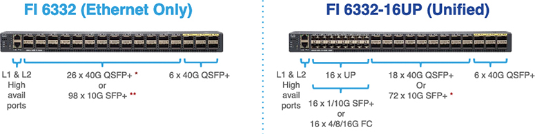
Figure 11-9 Cisco UCS Fabric Interconnect 6332
Ports on the Cisco UCS 6300 Series Fabric Interconnects can be configured to carry either Ethernet or Fibre Channel traffic. These ports are not reserved. They cannot be used by a Cisco UCS domain until you configure them. When you configure a port on a fabric interconnect, the administrative state is automatically set to enabled. If the port is connected to another device, this may cause traffic disruption. You can disable the port after it has been configured.
The Cisco UCS Fabric Interconnect 6300 Series supports splitting a single QSFP port into four 10-Gigabit Ethernet ports using a supported breakout cable. By default, there are 32 ports in the 40-Gigabit mode. These 40-Gigabit Ethernet ports are numbered in a 2-tuple naming convention. For example, the second 40-Gigabit Ethernet port is numbered as 1/2. The process of changing the configuration from 40-Gigabit Ethernet to 10-Gigabit Ethernet is called breakout, and the process of changing the configuration from 4 ×10-Gigabit Ethernet to 40-Gigabit Ethernet is called unconfigure. When you break out a 40-Gigabit Ethernet port into 10-Gigabit Ethernet ports, the resulting ports are numbered using a 3-tuple naming convention. For example, the breakout ports of the second 40-Gigabit Ethernet port are numbered as 1/2/1, 1/2/2, 1/2/3, and 1/2/4. Table 11-2 summarizes the constraints for breakout functionality for Cisco UCS 6300 Series Fabric Interconnects.
Table 11-2 Cisco UCS 6300 Port Breakout Summary

Note
Up to four breakout ports are allowed if QoS jumbo frames are used.
![]()
Fabric Interconnect and Fabric Extender Connectivity
Fabric Extenders (FEs) are extensions of the fabric interconnects (FIs) and act as remote line cards to form a distributed modular fabric system. The fabric extension is accomplished through the FEX fabric link, which is the connection between the fabric interconnect and the FEX. A minimum of one connection between the FI and FEX is required to provide server connectivity. Depending on the FEX model, subsequent connections can be up to eight links, which provides added bandwidth to the servers.
The Cisco UCS 2304 IOM (Fabric Extender) is an I/O module with 8 × 40-Gigabit backplane ports and 4 × 40-Gigabit uplink ports (see Figure 11-10). It can be hot-plugged into the rear of a Cisco UCS 5108 blade server chassis. A maximum of two UCS 2304 IOMs can be installed in a chassis. The Cisco UCS 2304 IOM provides chassis management control and blade management control, including control of the chassis, fan trays, power supply units, and blades. It also multiplexes and forwards all traffic from the blade servers in the chassis to the 10-Gigabit Ethernet uplink network ports that connect to the fabric interconnect. The IOM can also connect to a peer IOM to form a cluster interconnect.

Figure 11-10 Cisco UCS 2300 IOM
Figure 11-11 shows how the FEX modules in the blade chassis connect to the FIs. The 5108 chassis accommodates the following FEXs:
• Cisco UCS 2304
Note
The Cisco UCS 2304 Fabric Extender is not compatible with the Cisco UCS 6200 Fabric Interconnect series.
• Cisco UCS 2208XP
• Cisco UCS 2208XP
![]()

Figure 11-11 Connecting Blade Chassis Fabric Extenders to Fabric Interconnect
In a blade chassis, the FEX fabric link (the link between the FEX and the FI) supports two different types of connections:
• Discrete mode
• Port channel mode
In discrete mode, a half-width server slot is pinned to a given FEX fabric link. The supported numbers of links are 1, 2, 4, and 8, as shown in Table 11-3. Figure 11-12 shows an example of four FEX fabric link connections, and Figures 11-13 and 11-14 show an example of four FEX fabric link connections.
![]()
Table 11-3 Blade Chassis Slot to Link Mapping


Figure 11-12 Discrete Mode FEX Fabric Link Slot
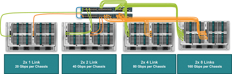
Figure 11-13 UCS 10-Gigabit Ethernet FEX to FI Connectivity
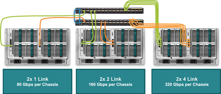
Figure 11-14 UCS 40-Gigabit Ethernet FEX to FI Connectivity
In port channel mode, the FEX fabric links are bundled into a single logical link (see Figure 11-15) to provide higher bandwidth to the servers. Depending on the FEX, up to eight links can be port channeled.

Figure 11-15 FEX Fabric Links in Port Channel Mode
The Adapter-FEX uses a mechanism to divide a single physical link into multiple virtual links or channels, as shown in Figure 11-16. Each channel is identified by a unique channel number, and its scope is limited to the physical link.
![]()

Figure 11-16 UCS FEX virtual links
The physical link connects a port on a server network adapter with an Ethernet port on the device, which allows the channel to connect a virtual network interface card (vNIC) on the server with a virtual Ethernet interface on the device.
Packets on each channel are tagged with a virtual network tag (VNTag) with a specific source virtual interface identifier (VIF). The VIF allows the receiver to identify which channel that the source transmit is using to the packet.
A rack-mount server has a different connectivity method. The Cisco C-Series support two types of connections:
• Single-wire management
• Dual-wire management
Cisco UCS Manager single-wire management supports an additional option to integrate the C-Series rack-mount server with the Cisco UCS Manager using the NC-SI. This option enables the Cisco UCS Manager to manage the C-Series rack-mount servers using a single wire for both management traffic and data traffic. When you use the single-wire management mode, one host-facing port on the FEX is sufficient to manage one rack-mount server instead of the two ports you would use in the Shared-LOM (LAN On Motherboard) mode. This connection method allows you to connect more rack-mount servers with the Cisco UCS Manager for integrated server management. You should make sure you have the correct server firmware for integration with the Cisco UCS Manager. If not, upgrade your server firmware before integrating the server with the Cisco UCS Manager. Figure 11-17 shows how the C-Series rack-mount chassis connect to the FEXs and FIs for single-wire management, with numbered elements as follows:
![]()
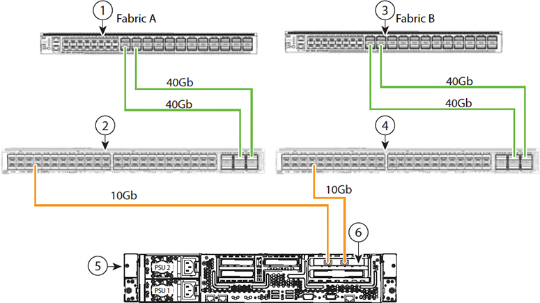
Figure 11-17 C-Series Rack Chassis with Single-Wire Management
1. Cisco UCS 6332-16UP FI (Fabric A)
2. Cisco Nexus 2232PP, 2232TM-E, or 2348UPQ (Fabric A)
3. Cisco UCS 6332-16UP FI (Fabric B)
4. Cisco Nexus 2232PP, 2232TM-E, or 2348UPQ (Fabric B)
5. Cisco UCS C-Series server
6. Cisco UCS VIC1225 in PCIe slot 1
The Cisco UCS dual-wire manager supports the existing rack server integration and management option through shared LOM, using two separate cables for data traffic and management traffic, as shown in Figure 11-18. The prerequisites for integration with the Cisco UCS Manager are built into the C-Series servers. You should make sure you have the correct server firmware for integration with the Cisco UCS Manager. If not, you need to upgrade your server firmware before integrating the server with the Cisco UCS Manager. Figure 11-18 shows how the C-Series rack-mount chassis connect to the FEXs and FIs for dual-wire management, with numbered elements as follows:
![]()

Figure 11-18 C-Series Rack-Mount Chassis with Dual-Wire Management
1. Cisco UCS 6332-16UP FI (Fabric A)
2. GLC-TE transceiver in FEX port (Fabric A)
3. Cisco Nexus 2232PP, 2232TM-E, or 2348UPQ (Fabric A)
4. Cisco UCS 6332-16UP FI (Fabric B)
5. GLC-TE transceiver in FEX port (Fabric B)
6. Cisco Nexus 2232PP, 2232TM-E, or 2348UPQ (Fabric B)
7. Cisco UCS C-Series server
8. 1-Gb Ethernet LOM ports
9. 10-Gb Adapter card in PCIe slot 1
![]()
Cisco UCS Virtualization Infrastructure
The Cisco UCS is a single integrated system with switches, cables, adapters, and servers all tied together and managed by unified management software. Thus, you are able to virtualize every component of the system at every level. The switch port, cables, adapter, and servers can all be virtualized.
Because of the virtualization capabilities at every component of the system, you have the unique ability to provide rapid provisioning of any service on any server on any blade through a system that is wired once. Figure 11-19 illustrates these virtualization capabilities.
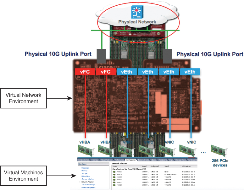
Figure 11-19 UCS Virtualization Infrastructure
The Cisco UCS Virtual Interface Card 1400 Series (Figure 11-19) extends the network fabric directly to both servers and virtual machines so that a single connectivity mechanism can be used to connect both physical and virtual servers with the same level of visibility and control. Cisco VICs provide complete programmability of the Cisco UCS I/O infrastructure, with the number and type of I/O interfaces configurable on demand with a zero-touch model.
Cisco VICs support Cisco Single Connect technology, which provides an easy, intelligent, and efficient way to connect and manage computing in your data center. Cisco Single Connect unifies LAN, SAN, and systems management into one simplified link for rack servers, blade servers, and virtual machines. This technology reduces the number of network adapters, cables, and switches needed and radically simplifies the network, reducing complexity. Cisco VICs can support 256 PCI Express (PCIe) virtual devices, either virtual network interface cards (vNICs) or virtual host bus adapters (vHBAs), with a high rate of I/O operations per second (IOPS), support for lossless Ethernet, and 10/25/40/100-Gbps connection to servers. The PCIe Generation 3 × 16 interface helps ensure optimal bandwidth to the host for network-intensive applications, with a redundant path to the fabric interconnect. Cisco VICs support NIC teaming with fabric failover for increased reliability and availability. In addition, it provides a policy-based, stateless, agile server infrastructure for your data center.
The VIC 1400 Series is designed exclusively for the M5 generation of UCS B-Series blade servers, C-Series rack servers, and S-Series storage servers. The adapters are capable of supporting 10/25/40/100-Gigabit Ethernet and Fibre Channel over Ethernet. It incorporates Cisco’s next-generation converged network adapter (CNA) technology and offers a comprehensive feature set, providing investment protection for future feature software releases. In addition, the VIC supports Cisco’s Data Center Virtual Machine Fabric Extender (VM-FEX) technology. This technology extends the Cisco UCS Fabric Interconnect ports to virtual machines, simplifying server virtualization deployment.
The Cisco UCS VIC 1400 Series provides the following features and benefits (see Figure 11-20):
• Stateless and agile platform: The personality of the card is determined dynamically at boot time using the service profile associated with the server. The number, type (NIC or HBA), identity (MAC address and World Wide Name [WWN]), failover policy, bandwidth, and quality of service (QoS) policies of the PCIe interfaces are all determined using the service profile. The capability to define, create, and use interfaces on demand provides a stateless and agile server infrastructure.
• Network interface virtualization: Each PCIe interface created on the VIC is associated with an interface on the Cisco UCS Fabric Interconnect, providing complete network separation for each virtual cable between a PCIe device on the VIC and the interface on the fabric interconnect.
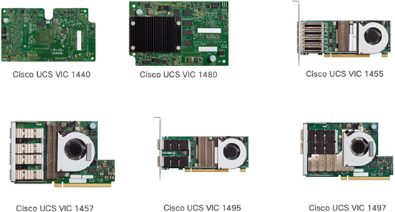
Figure 11-20 Cisco UCS Virtual Interface Cards (VICs)
UCS M5 B-Series VIC:
• Cisco VIC 1440
• Single-port 40-Gigabit Ethernet or 4 × 10-Gbps Ethernet/FCoE capable modular LAN On Motherboard (mLOM).
• Cisco UCS VIC 1440 capabilities are enabled for two ports of 40-Gbps Ethernet.
• UCS VIC 1440 enables a policy-based, stateless, agile server infrastructure that can present to the host PCIe standards-compliant interfaces that can be dynamically configured as either NICs or HBAs.
• Cisco VIC 1480
• Single-port 40-Gigabit Ethernet s or 4 × 10-Gigabit Ethernet/FCoE capable mezzanine card (mezz).
• UCS VIC 1480 enables a policy-based, stateless, agile server infrastructure that can present PCIe standards-compliant interfaces to the host that can be dynamically configured as either NICs or HBAs.
UCS M5 C-Series VIC:
• Cisco VIC 1455
• Quad-port Small Form-Factor Pluggable (SFP28) half-height PCIe card.
• Supports 10/25-Gigabit Ethernet or FCoE. The card can present PCIe standards-compliant interfaces to the host, and these can be dynamically configured as either NICs or HBAs.
• Cisco VIC 1457
• Quad-port Small Form-Factor Pluggable (SFP28) mLOM card.
• Supports 10/25-Gigabit Ethernet or FCoE. The card can present PCIe standards-compliant interfaces to the host, and these can be dynamically configured as either NICs or HBAs.
• Cisco VIC 1495
• Dual-port Quad Small Form-Factor (QSFP28) PCIe.
• Supports 40/100-Gigabit Ethernet or FCoE. The card can present PCIe standards-compliant interfaces to the host, and these can be dynamically configured as NICs or HBAs.
• Cisco VIC 1497
• Dual-port Quad Small Form-Factor (QSFP28) mLOM card.
• The card supports 40/100-Gigabit Ethernet or FCoE. The card can present PCIe standards-compliant interfaces to the host, and these can be dynamically configured as NICs or HBAs.
Cisco UCS Initial Setup and Management
The Cisco UCS Manager enables you to manage general and complex server deployments. For example, you can manage a general deployment with a pair of fabric interconnects, which is the redundant server access layer that you get with the first chassis that can scale up to 20 chassis and up to 160 physical servers. This can be a combination of blades and rack-mount servers to support the workload in your environment. As you add more servers, you can continue to perform server provisioning, device discovery, inventory, configuration, diagnostics, monitoring, fault detection, and auditing.
Beginning with release 4.0(2a), the Cisco UCS Manager extends support for all existing features on the following Cisco UCS hardware unless specifically noted:
• Cisco UCS C480 M5 ML Server
• Cisco UCS VIC 1495
• Cisco UCS VIC 1497
• Cisco UCS 6454 Fabric Interconnect
• Cisco UCS VIC 1455
• Cisco UCS VIC 1457
• Cisco UCS C125 M5 Server
By default, the Cisco UCS 6454 Fabric Interconnect, the Cisco UCS 6332 FIs, the Cisco UCS Mini 6324 FIs, and the UCS 6200 Series FIs include centralized management. You can manage the Cisco UCS blade servers and rack-mount servers that are in the same domain from one console. You can also manage the Cisco UCS Mini from the Cisco UCS Manager.
To ensure optimum server performance, you can configure the amount of power that you allocate to servers. You can also set the server boot policy, the location from which the server boots, and the order in which the boot devices are invoked. You can create service profiles for the Cisco UCS B-Series blade servers and the Cisco UCS Mini to assign to servers. Service profiles enable you to assign BIOS settings, security settings, the number of vNICs and vHBAs, and anything else that you want to apply to a server. Initial configuration of fabric interconnects is performed using the console connection. It is essential to maintain symmetric Cisco UCS Manager versions between the fabric interconnects in a domain.
Follow these steps to perform the initial configuration for the Cisco UCS Manager:
Step 1. Power on the fabric interconnect. You see the power-on self-test messages as the fabric interconnect boots.
Step 2. If the system obtains a lease IPv4 or IPv6 address, go to step 6; otherwise, continue to the next step.
Step 3. Connect to the console port.
Step 4. At the installation method prompt, enter GUI.
Step 5. If the system cannot access a DHCP server, you are prompted to enter the following information:
• IPv4 or IPv6 address for the management port on the fabric interconnect
• IPv4 subnet mask or IPv6 prefix for the management port on the fabric interconnect
• IPv4 or IPv6 address for the default gateway assigned to the fabric interconnect
Note
In a cluster configuration, both fabric interconnects must be assigned the same management interface address type during setup.
Step 6. Copy the web link from the prompt into a web browser and go to the Cisco UCS Manager GUI launch page.
Step 7. On the Cisco UCS Manager GUI launch page, select Express Setup.
Step 8. On the Express Setup page, select Initial Setup and click Submit.
Step 9. In the Cluster and Fabric Setup area, do the following:
• Click the Enable Clustering option.
• For the Fabric Setup option, select Fabric A.
• In the Cluster IP Address field, enter the IPv4 or IPv6 address that the Cisco UCS Manager will use.
Step 10. In the System Setup area, complete the following fields:

Step 11. Click Submit. A page then displays the results of your setup operation.
Another option is to use the command-line interface (CLI) to configure the primary fabric interconnect as follows:
Step 1. Connect to the console port.
Step 2. Power on the fabric interconnect. You see the power-on self-test messages as the fabric interconnect boots.
Step 3. When the unconfigured system boots, it prompts you for the setup method to be used. Enter console to continue the initial setup using the console CLI.
Step 4. Enter setup to continue as an initial system setup.
Step 5. Enter y to confirm that you want to continue the initial setup.
Step 6. Enter the password for the admin account.
Step 7. To confirm, reenter the password for the admin account.
Step 8. Enter yes to continue the initial setup for a cluster configuration.
Step 9. Enter the fabric interconnect fabric (either A or B).
Step 10. Enter the system name.
Step 11. Enter the IPv4 or IPv6 address for the management port of the fabric interconnect. If you enter an IPv4 address, you are prompted to enter an IPv4 subnet mask. If you enter an IPv6 address, you are prompted to enter an IPv6 network prefix.
Step 12. Enter the respective IPv4 subnet mask or IPv6 network prefix; then press Enter. You are prompted for an IPv4 or IPv6 address for the default gateway, depending on the address type you entered for the management port of the fabric interconnect.
Step 13. Enter either of the following:
• IPv4 address of the default gateway
• IPv6 address of the default gateway
Step 14. Enter yes if you want to specify the IP address for the DNS server or no if you do not.
Step 15. (Optional) Enter the IPv4 or IPv6 address for the DNS server. The address type must be the same as the address type of the management port of the fabric interconnect.
Step 16. Enter yes if you want to specify the default domain name or no if you do not.
Step 17. (Optional) Enter the default domain name.
Step 18. Review the setup summary and enter yes to save and apply the settings, or enter no to go through the Setup wizard again to change some of the settings. If you choose to go through the Setup wizard again, it provides the values you previously entered, and the values appear in brackets. To accept previously entered values, press Enter.
Example 11-1 sets up the first fabric interconnect for a cluster configuration using the console to set IPv4 management addresses.
Example 11-1 UCS FI IPv4 Initialization
Enter the installation method (console/gui)? console
Enter the setup mode (restore from backup or initial setup) [restore/setup]? setup
You have chosen to setup a new switch. Continue? (y/n): y
Enter the password for “admin”: adminpassword
Confirm the password for “admin”: adminpassword
Do you want to create a new cluster on this switch (select ‘no’ for standalone setup or if you want this switch to be added to an existing cluster)? (yes/no) [n]: yes
Enter the switch fabric (A/B): A
Enter the system name: dccor
Mgmt0 IPv4 address: 192.168.10.11
Mgmt0 IPv4 netmask: 255.255.255.0
IPv4 address of the default gateway: 192.168.0.1
Virtual IPv4 address: 192.168.0.10
Configure the DNS Server IPv4 address? (yes/no) [n]: yes
DNS IPv4 address: 198.18.133.200
Configure the default domain name? (yes/no) [n]: yes
Default domain name: domainname.com
Join centralized management environment (UCS Central)? (yes/no) [n]: no
Following configurations will be applied:
  Switch Fabric=A
  System Name=dccor
  Management IP Address=192.168.0.11
  Management IP Netmask=255.255.255.0
  Default Gateway=192.168.0.1
  Cluster Enabled=yes
  Virtual Ip Address=192.168.0.10
  DNS Server=198.18.133.200
  Domain Name=domainname.com
Apply and save the configuration (select ‘no’ if you want to re-enter)? (yes/no): yes
Example 11-2 sets up the first fabric interconnect for a cluster configuration using the console to set IPv6 management addresses:
Example 11-2 UCS FI IPv6 Initialization
Enter the installation method (console/gui)? console
Enter the setup mode (restore from backup or initial setup) [restore/setup]? setup
You have chosen to setup a new switch. Continue? (y/n): y
Enter the password for “admin”: adminpassword
Confirm the password for “admin”: adminpassword
Do you want to create a new cluster on this switch (select ‘no’ for standalone setup or if
you want this switch to be added to an existing cluster)? (yes/no) [n]: yes
Enter the switch fabric (A/B): A
Enter the system name: dccor
Mgmt0 address: 2020::207
Mgmt0 IPv6 prefix: 64
IPv6 address of the default gateway: 2020::1
Configure the DNS Server IPv6 address? (yes/no) [n]: yes
DNS IP address: 2020::201
Configure the default domain name? (yes/no) [n]: yes
Default domain name: domainname.com
Join centralized management environment (UCS Central)? (yes/no) [n]: no
Following configurations will be applied:
Switch Fabric=A
System Name=dccor
Enforced Strong Password=no
Physical Switch Mgmt0 IPv6 Address=2020::207
Physical Switch Mgmt0 IPv6 Prefix=64
Default Gateway=2020::1
Ipv6 value=1
DNS Server=2020::201
Domain Name=domainname.com
Apply and save the configuration (select ‘no’ if you want to re-enter)? (yes/no): yes
To configure the subordinate fabric interconnect using the GUI, follow these steps:
Step 1. Power up the fabric interconnect. You see the power-on self-test message as the fabric interconnect boots.
Step 2. It the system obtains a lease, go to step 6; otherwise, continue to the next step.
Step 3. Connect to the console port.
Step 4. At the installation method prompt, enter GUI.
Step 5. If the system cannot access a DHCP server, you are prompted to enter the following information:
• IPv4 or IPv6 address for the management port on the fabric interconnect
• IPv4 subnet mask or IPv6 prefix for the management port on the fabric interconnect
• IPv4 or IPv6 address for the default gateway assigned to the fabric interconnect
Note
In a cluster configuration, both fabric interconnects must be assigned the same management interface address type during setup.
Step 6. Copy the web link from the prompt into a web browser and go to the Cisco UCS Manager GUI launch page.
Step 7. On the Cisco UCS Manager GUI launch page, select Express Setup.
Step 8. On the Express Setup page, select Initial Setup and click Submit. The fabric interconnect should detect the configuration information for the first fabric interconnect.
Step 9 In the Cluster and Fabric Setup Area, do the following:
• Select the Enable Clustering option.
• For the Fabric Setup option, make sure Fabric B is selected.
Step 10. In the System Setup Area, enter the password for the Admin account into the Admin Password of Master field. The Manager Initial Setup Area is displayed.
Step 11. In the Manager Initial Setup Area, the field that is displayed depends on whether you configured the first fabric interconnect with an IPv4 or IPv6 management address. Complete the field that is appropriate for your configuration, as follows:
• Peer FI is IPv4 Cluster enabled. Please Provide Local fabric interconnect Mgmt0 IPv4 Address: Enter an IPv4 address for the Mgmt0 interface on the local fabric interconnect.
• Peer FI is IPv6 Cluster Enabled. Please Provide Local fabric interconnect Mgmt0 IPv6 Address: Enter an IPv6 address for the Mgmt0 interface on the local fabric interconnect.
Step 12. Click Submit. A page displays the results of your setup operation.
To configure the subordinate fabric interconnect using the CLI, follow these steps:
Step 1. Connect to the console port.
Step 2. Power up the fabric interconnect. You see the power-on self-test messages as the fabric interconnect boots.
Step 3. When the unconfigured system boots, it prompts you for the setup method to be used. Enter console to continue the initial setup using the console CLI.
Note
The fabric interconnect should detect the peer fabric interconnect in the cluster. If it does not, check the physical connections between the L1 and L2 ports, and verify that the peer fabric interconnect has been enabled for a cluster configuration.
Step 4. Enter y to add the subordinate fabric interconnect to the cluster.
Step 5. Enter the admin password of the peer fabric interconnect.
Step 6. Enter the IP address for the management port on the subordinate fabric interconnect.
Step 7. Review the setup summary and enter yes to save and apply the settings, or enter no to go through the Setup wizard again to change some of the settings. If you choose to go through the Setup wizard again, it provides the values you previously entered, and the values appear in brackets. To accept previously entered values, press Enter.
Example 11-3 sets up the second fabric interconnect for a cluster configuration using the console and the IPv4 address of the peer.
Example 11-3 UCS Second FI IPv4 Initialization
Enter the installation method (console/gui)? console
Installer has detected the presence of a peer Fabric interconnect. This Fabric interconnect
will be added to the cluster. Continue (y/n) ? y
Enter the admin password of the peer Fabric Interconnect: adminpassword
Peer Fabric interconnect Mgmt0 IPv4 Address: 192.168.10.11
Apply and save the configuration (select ‘no’ if you want to re-enter)? (yes/no): yes
Example 11-4 sets up the second fabric interconnect for a cluster configuration using the console and the IPv6 address of the peer.
Example 11-4 UCS Second FI IPv6 Initialization
Enter the installation method (console/gui)? console
Installer has detected the presence of a peer Fabric interconnect. This Fabric interconnect
will be added to the cluster. Continue (y/n) ? y
Enter the admin password of the peer Fabric Interconnect: adminpassword
Peer Fabric interconnect Mgmt0 IPv6 Address: 2020::207
Apply and save the configuration (select ‘no’ if you want to re-enter)? (yes/no): yes
You can verify that both fabric interconnect configurations are complete by logging in to the fabric interconnect via the SSH or GUI and verifying the cluster status through the CLI as the commands in Table 11-4 or through the GUI, as shown in Figure 11-21.
![]()
Table 11-4 Cluster Verification CLI


Figure 11-21 Cisco UCS Manager Cluster Verification
Fabric Interconnect Connectivity and Configurations
A fully redundant Cisco Unified Computing System consists of two independent fabric planes: Fabric A and Fabric B. Each plane consists of a central fabric interconnect (Cisco UCS 6300 or 6200 Series Fabric Interconnects) connected to an I/O module (Fabric Extender) in each blade chassis. The two fabric interconnects are completely independent from the perspective of the data plane; the Cisco UCS can function with a single fabric interconnect if the other fabric is offline or not provisioned (see Figure 11-22).


Figure 11-22 UCS Fabric Interconnect (FI) Status
The following steps show how to determine the primary fabric interconnect:
Step 1. In the Navigation pane, click Equipment.
Step 2. Expand Equipment > Fabric Interconnects.
Step 3. Click the fabric interconnect for which you want to identify the role.
Step 4. In the Work pane, click the General tab.
Step 5. In the General tab, click the down arrows on the High Availability Details bar to expand that area.
Step 6. View the Leadership field to determine whether the fabric interconnect is primary or subordinate.
Note
If the admin password is lost, you can determine the primary and secondary roles of the fabric interconnects in a cluster by opening the Cisco UCS Manager GUI from the IP addresses of both fabric interconnects. The subordinate fabric interconnect fails with the following message: “UCSM GUI is not available on secondary node.”
The fabric interconnect is the core component of the Cisco UCS. Cisco UCS Fabric Interconnects provide uplink access to LAN, SAN, and out-of-band management segments, as shown in Figure 11-23. Cisco UCS infrastructure management is handled through the embedded management software, the Cisco UCS Manager, for both hardware and software management. The Cisco UCS Fabric Interconnects are top-of-rack devices and provide unified access to the Cisco UCS domain.
![]()

Figure 11-23 Cisco UCS Components Logical Connectivity
All network endpoints, such as host bus adapters (HBAs) and management entities such as Cisco Integrated Management Controllers (CIMCs; formerly referred to as baseboard management controllers, or BMCs), are dual-connected to both fabric planes and thus can work in an active-active configuration.
Virtual port channels (vPCs) are not supported on the fabric interconnects, although the upstream LAN switches to which they connect can be vPC or Virtual Switching System (VSS) peers.
Cisco UCS Fabric Interconnects provide network connectivity and management for the connected servers. They run the Cisco UCS Manager control software and consist of expansion modules for the Cisco UCS Manager software.
Uplink Connectivity
Fabric interconnect ports configured as uplink ports are used to connect to upstream network switches. You can connect these uplink ports to upstream switch ports as individual links or as links configured as port channels. Port channel configurations provide bandwidth aggregation as well as link redundancy.
You can achieve northbound connectivity from the fabric interconnect through a standard uplink, a port channel, or a virtual port channel configuration. The port channel name and ID configured on the fabric interconnect should match the name and ID configuration on the upstream Ethernet switch.
It is also possible to configure a port channel as a vPC, where port channel uplink ports from a fabric interconnect are connected to different upstream switches. After all uplink ports are configured, you can create a port channel for these ports.
Downlink Connectivity
Each fabric interconnect is connected to I/O modules in the Cisco UCS chassis, which provides connectivity to each blade server. Internal connectivity from blade servers to IOMs is transparently provided by the Cisco UCS Manager using the 10BASE-KR Ethernet standard for backplane implementations, and no additional configuration is required. You must configure the connectivity between the fabric interconnect server ports and IOMs. Each IOM, when connected with the fabric interconnect server port, behaves as a line card to fabric interconnect; hence, IOMs should never be cross-connected to the fabric interconnect. Each IOM is connected directly to a single fabric interconnect.
The Fabric Extender (also referred to as the IOM, or FEX) logically extends the fabric interconnects to the blade server. The best analogy is to think of it as a remote line card that’s embedded in the blade server chassis, allowing connectivity to the external world. IOM settings are pushed via the Cisco UCS Manager and are not managed directly. The primary functions of this module are to facilitate blade server I/O connectivity (internal and external), multiplex all I/O traffic up to the fabric interconnects, and help monitor and manage the Cisco UCS infrastructure. You should configure fabric interconnect ports that should be connected to downlink IOM cards as server ports. You need to make sure there is physical connectivity between the fabric interconnect and IOMs. You must also configure the IOM ports and the global chassis discovery policy.
![]()
Fabric Interconnect Port Modes
The port mode determines whether a unified port on the fabric interconnect is configured to carry Ethernet or Fibre Channel traffic. You configure the port mode in the Cisco UCS Manager. However, the fabric interconnect does not automatically discover the port mode.
Changing the port mode deletes the existing port configuration and replaces it with a new logical port. Any objects associated with that port configuration, such as VLANs and VSANS, are also removed. There is no restriction on the number of times you can change the port mode for a unified port.
![]()
When you set the port mode to Ethernet, you can configure the following Ethernet port types:
• Server ports
• Ethernet uplink ports
• Ethernet port channel members
• Appliance ports
• Appliance port channel members
• SPAN destination ports
• SPAN source ports
Note
For SPAN source ports, you configure one of the port types and then configure the port as a SPAN source.
For Fiber Channel, you can configure the following port types:
• Fibre Channel uplink ports
• Fibre Channel port channel members
• Fibre Channel storage ports
• FCoE Uplink ports
• SPAN source ports
A port must be explicitly defined as a specific type, and this type defines the port behavior. For example, discovery of components such as Fabric Extenders or blades is performed only on server ports. Similarly, uplink ports are automatically configured as IEEE 802.1Q trunks for all VLANs defined on the fabric interconnect.
The following steps show how to verify fabric interconnect neighbors:
Step 1. In the Navigation pane, click Equipment.
Step 2. In the Equipment tab, expand Equipment > Fabric Interconnects.
Step 3. Click the fabric interconnect for which you want to view the LAN or SAN or LLDP neighbors.
Step 4. In the Work pane, click the Neighbors tab.
Step 5. Click the LAN or SAN or LLDP subtab. This subtab lists all the LAN or SAN or LLDP neighbors of the specified Fabric Interconnect. (See Figure 11-24.)
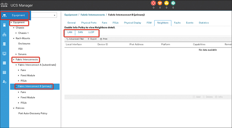
Figure 11-24 UCS Fabric Interconnect (FI) Neighbors Detail
Note
In either Ethernet switching mode, a fabric interconnect does not require an upstream switch for Layer 2 traffic between two servers connected to it on the same fabric.
An external switch is required for switching Layer 2 traffic between servers if vNICs belonging to the same VLAN are mapped to different fabric interconnects (see Figure 11-25).

Figure 11-25 UCS FI to External LAN Connection
Fabric Failover for Ethernet: High-Availability vNIC
To understand the switching mode behavior, you need to understand the fabric-based failover feature for Ethernet in the Cisco UCS. Each adapter in the Cisco UCS is a dual-port adapter that connects to both fabrics (A and B). The two fabrics in the Cisco UCS provide failover protection in the event of planned or unplanned component downtime in one of the fabrics. Typically, host software—such as NIC teaming for Ethernet and PowerPath or multipath I/O (MPIO) for Fibre Channel—provides failover across the two fabrics (see Figure 11-26).
![]()

Figure 11-26 UCS Fabric Traffic Failover Example
A vNIC in the Cisco UCS is a host-presented PCI device that is centrally managed by the Cisco UCS Manager. The fabric-based failover feature, which you enable by selecting the high-availability vNIC option in the service profile definition, allows network interface virtualization (NIV)-capable adapters (Cisco virtual interface card, or VIC) and the fabric interconnects to provide active-standby failover for Ethernet vNICs without any NIC-teaming software on the host.
For unicast traffic failover, the fabric interconnect in the new path sends gratuitous Address Resolution Protocols (gARPs). This process refreshes the forwarding tables on the upstream switches.
For multicast traffic, the new active fabric interconnect sends an Internet Group Management Protocol (IGMP) Global Leave message to the upstream multicast router. The upstream multicast router responds by sending an IGMP query that is flooded to all vNICs. The host OS responds to these IGMP queries by rejoining all relevant multicast groups. This process forces the hosts to refresh the multicast state in the network in a timely manner.
Cisco UCS fabric failover is an important feature because it reduces the complexity of defining NIC teaming software for failover on the host. It does this transparently in the fabric based on the network property that is defined in the service profile.
Ethernet Switching Mode
The Ethernet switching mode determines how the fabric interconnect behaves as a switching device between the servers and the network. The fabric interconnect operates in either of the following Ethernet switching modes:
• End-host mode
• Switching mode
In end-host mode, the Cisco UCS presents an end host to an external Ethernet network. The external LAN sees the Cisco UCS Fabric Interconnect as an end host with multiple adapters (see Figure 11-27).

Figure 11-27 UCS FI End-Host Mode Ethernet
End-host mode allows the fabric interconnect to act as an end host to the network, representing all servers (hosts) connected to it through vNICs. This behavior is achieved by pinning (either dynamically pinning or hard pinning) vNICs to uplink ports, which provides redundancy to the network, and makes the uplink ports appear as server ports to the rest of the fabric.
In end-host mode, the fabric interconnect does not run the Spanning Tree Protocol (STP), but it avoids loops by denying uplink ports from forwarding traffic to each other and by denying egress server traffic on more than one uplink port at a time. End-host mode is the default Ethernet switching mode and should be used if either of the following is used upstream:
• Layer 2 switching for Layer 2 aggregation
• vPC or VSS aggregation layer
Note
When you enable end-host mode, if a vNIC is hard pinned to an uplink port and this uplink port goes down, the system cannot repin the vNIC, and the vNIC remains down.
Server links (vNICs on the blades) are associated with a single uplink port, which may also be a port channel. This association process is called pinning, and the selected external interface is called a pinned uplink port. The pinning process can be statically configured when the vNIC is defined or dynamically configured by the system. In end-host mode, pinning is required for traffic flow to a server.
Static pinning is performed by defining a pin group and associating the pin group with a vNIC. Static pinning should be used in scenarios in which a deterministic path is required. When the target (as shown on Figure 11-28) on Fabric Interconnect A goes down, the corresponding failover mechanism of the vNIC goes into effect, and traffic is redirected to the target port on Fabric Interconnect B.

Figure 11-28 UCS LAN Pinning Group Configuration
If the pinning is not static, the vNIC is pinned to an operational uplink port on the same fabric interconnect, and the vNIC failover mechanisms are not invoked until all uplink ports on that fabric interconnect fail. In the absence of Spanning Tree Protocol, the fabric interconnect uses various mechanisms for loop prevention while preserving an active-active topology.
In the Cisco UCS, two types of Ethernet traffic paths will have different characteristics—Unicast and Multicast/Broadcast.
• Unicast traffic paths in the Cisco UCS are shown in Figure 11-29. Characteristics of unicast traffic in the Cisco UCS include the following:
• Each server link is pinned to exactly one uplink port (or port channel).
• Server-to-server Layer 2 traffic is locally switched.
• Server-to-network traffic goes out on its pinned uplink port.
• Network-to-server unicast traffic is forwarded to the server only if it arrives on a pinned uplink port. This feature is called the Reverse Path Forwarding (RPF) check.
• Server traffic received on any uplink port, except its pinned uplink port, is dropped (called the deja-vu check).
• The server MAC address must be learned before traffic can be forwarded to it.
![]()
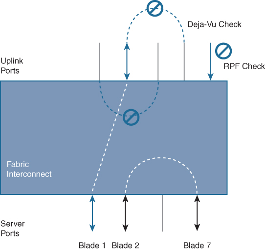
Figure 11-29 UCS Unicast Traffic Path
• Multicast/broadcast traffic paths in the Cisco UCS are shown in Figure 11-30. Characteristics of multicast/broadcast traffic in the Cisco UCS include the following:
• Broadcast traffic is pinned on exactly one uplink port in the Cisco UCS Manager, and the incoming broadcast traffic is pinned on a per-VLAN basis, depending on uplink port VLAN membership.
• IGMP multicast groups are pinned based on IGMP snooping. Each group is pinned to exactly one uplink port.
• Server-to-server multicast traffic is locally switched.
• RPF and deja-vu checks also apply to multicast traffic.
![]()
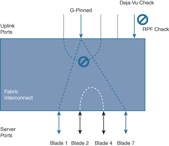
Figure 11-30 Multicast and Broadcast Traffic Summary
In switching mode the fabric interconnect runs STP to avoid loops, broadcast and multicast packets are handled in the traditional way. You should use the switching mode only if the fabric interconnect is directly connected to a router or if either of the following is used upstream:
• Layer 3 aggregation
• VLAN in a box
In Ethernet switching mode (see Figure 11-31), the Cisco UCS Fabric Interconnects act like traditional Ethernet switches with support for Spanning Tree Protocol on the uplink ports.

Figure 11-31 UCS FI Switch Mode Ethernet
The following are Ethernet switching mode features:
• Spanning Tree Protocol is run on the uplink ports per VLAN as defined by Cisco Per-VLAN Spanning Tree Plus (PVST+).
• Configuration of Spanning Tree Protocol parameters (such as bridge priority and hello timers) is not supported.
• VLAN Trunk Protocol (VTP) is not supported.
• MAC address learning and aging occur on both the server and uplink ports as in a typical Layer 2 switch.
• Upstream links are blocked according to Spanning Tree Protocol rules.
• In most cases, end-host mode is preferable because it offers scalability and simplicity for server administrators when connecting to an upstream network. However, there are other factors to consider when selecting the appropriate switching mode, including the following:
• Scalability
• Efficient use of bandwidth
• Fabric failover
• Active-active link utilization
• Disjoint Layer 2 domain or a loop-free topology
• Optimal network behavior for the existing network topology
• Application-specific requirements
Note
For both Ethernet switching modes, even when vNICs are hard-pinned to uplink ports, all server-to-server unicast traffic in the server array is sent only through the fabric interconnect and is never sent through uplink ports. Server-to-server multicast and broadcast traffic is sent through all uplink ports in the same VLAN.
Note
Cisco UCS Manager Release 4.0(2) and later releases support Ethernet and Fibre Channel switching modes on Cisco UCS 6454 Fabric Interconnects.
To configure Ethernet switching mode (see Figure 11-32), follow these steps:
Step 1. In the Navigation pane, click Equipment.

Figure 11-32 Cisco UCS Switch Fabric Mode Configuration
Step 2. Expand Equipment > Fabric Interconnects > Fabric_Interconnect_Name.
Step 3. In the Work pane, click the General tab.
Step 4. In the Actions area of the General tab, click one of the following links:
• Set Ethernet Switching Mode
• Set Ethernet End-Host Mode
Note
The link for the current mode is dimmed.
Step 5. In the dialog box, click Yes. The Cisco UCS Manager restarts the fabric interconnect, logs you out, and disconnects the Cisco UCS Manager GUI.
Note
When you change the Ethernet switching mode, the Cisco UCS Manager logs you out and restarts the fabric interconnect. For a cluster configuration, the Cisco UCS Manager restarts both fabric interconnects. The subordinate fabric interconnect reboots first as a result of the change in switching mode. The primary fabric interconnect reboots only after you acknowledge it in Pending Activities. The primary fabric interconnect can take several minutes to complete the change in Ethernet switching mode and become system ready. The existing configuration is retained. While the fabric interconnects are rebooting, all blade servers lose LAN and SAN connectivity, causing a complete outage of all services on the blades. This might cause the operating system to fail.
In some commonly deployed LAN topologies, switch mode provides the best network behavior. A typical example is a switch directly connected to a pair of Hot Standby Router Protocol (HSRP) routers that are the Spanning Tree Protocol roots on different VLANs. Switch mode provides the optimal path because of the use of Spanning Tree Protocol. For example, a vNIC belonging to an odd-numbered VLAN can be dynamically pinned to link X on Fabric Interconnect A (see Figure 11-33). As a result of this process, traffic traverses an extra hop to the HSRP master.

Figure 11-33 VLANs Load-Balanced Across a Pair of Switches
When a switch is directly connected to a pair of HRSP routers, the recommended Ethernet switching mode is switch mode because it provides the optimal path. End-host mode can be used if static pinning is employed.
UCS Device Discovery
The chassis connectivity policy determines whether a specific chassis is included in a fabric port channel after chassis discovery. This policy is helpful for users who want to configure one or more chassis differently from what is specified in the global chassis discovery policy. The chassis connectivity policy also allows for different connectivity modes per fabric interconnect, further expanding the level of control offered with regards to chassis connectivity.
By default, the chassis connectivity policy is set to global. This means that connectivity control is configured when the chassis is newly discovered, using the settings configured in the chassis discovery policy. Once the chassis is discovered, the chassis connectivity policy controls whether the connectivity control is set to none or port channel.
Chassis /FEX Discovery
The chassis discovery policy determines how the system reacts when you add a new chassis. The Cisco UCS Manager uses the settings in the chassis discovery policy to determine the minimum threshold for the number of links between the chassis and the fabric interconnect and whether to group links from the IOM to the fabric interconnect in a fabric port channel. In a Cisco UCS Mini setup, chassis discovery policy is supported only on the extended chassis.
The Cisco UCS Manager cannot discover any chassis that is wired for fewer links than are configured in the chassis/FEX discovery policy. For example, if the chassis/FEX discovery policy is configured for four links, the Cisco UCS Manager cannot discover any chassis that is wired for one link or two links. Reacknowledgement of the chassis resolves this issue.
Rack Server Discovery Policy
The rack server discovery policy determines how the system reacts when you add a new rack-mount server. The Cisco UCS Manager uses the settings in the rack server discovery policy to determine whether any data on the hard disks is scrubbed and whether server discovery occurs immediately or needs to wait for explicit user acknowledgment.
The Cisco UCS Manager cannot discover any rack-mount server that has not been correctly cabled and connected to the fabric interconnects. The steps to configure rack server discovery are as follows:
Step 1. In the Navigation pane, click Equipment.
Step 2. Click the Equipment node. In the Work pane, click the Policies tab.
Step 3. Click the Global Policies subtab.
Step 4. In the Rack Server Discovery Policy area, specify the action that you want to occur when a new rack server is added and specify the scrub policy. Then click Save Changes.
Initial Server Setup for Standalone UCS C-Series
Use the following procedure to perform initial setup on a UCS C-Series server:
Step 1. Power up the server. Wait for approximately two minutes to let the server boot in standby power during the first bootup. You can verify power status by looking at the Power Status LED:
• Off: There is no AC power present in the server.
• Amber: The server is in standby power mode. Power is supplied only to the CIMC and some motherboard functions.
• Green: The server is in main power mode. Power is supplied to all server components.
Note
Verify server power requirements because some servers (UCS C-240, for example) require 220V instead of 110V.
Note
During bootup, the server beeps once for each USB device that is attached to the server. Even if no external USB devices are attached, there is a short beep for each virtual USB device, such as a virtual floppy drive, CD/DVD drive, keyboard, or mouse. A beep is also emitted if a USB device is hot-plugged or hot-unplugged during the BIOS power-on self-test (POST), or while you are accessing the BIOS Setup utility or the EFI shell.
Step 2. Connect a USB keyboard and VGA monitor by using the supplied Kernel-based Virtual Machine (KVM) cable connected to the KVM connector on the front panel. You can use the VGA and USB ports on the rear panel. However, you cannot use the front-panel VGA and the rear-panel VGA at the same time. If you are connected to one VGA connector and you then connect a video device to the other connector, the first VGA connector is disabled.
Step 3. Open the Cisco IMC Configuration Utility as follows:
• Press the Power button to boot the server. Watch for the prompt to press F8.
• During bootup, press F8 when prompted to open the Cisco IMC Configuration Utility, as shown in Figure 11-34.
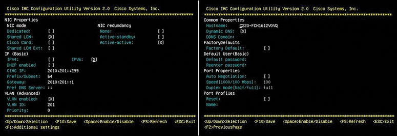
Figure 11-34 Standalone UCS CIMC Configuration Utility
Note
The first time that you enter the Cisco IMC Configuration Utility, you are prompted to change the default password. The default password is password.
The following are the requirements for a strong password:
• The password can have a minimum of 8 characters and a maximum of 14 characters.
• The password must not contain the user’s name.
• The password must contain characters from three of the following four categories:
• English uppercase letters (A through Z)
• English lowercase letters (a through z)
• Base 10 digits (0 through 9)
• Nonalphabetic characters (!, @, #, $, %, ^, &, *, -, _, =, “)
Step 4. Set NIC mode and NIC redundancy as follows:
• Set the NIC mode to your choice for which ports to use to access the CIMC for server management:
• Shared LOM EXT (default): This is shared LOM extended mode. This is the factory-default setting, along with Active-active NIC redundancy and DHCP-enabled. With this mode, the shared LOM and Cisco card interfaces are both enabled.
In this mode, DHCP replies are returned to both the shared LOM ports and the Cisco card ports. If the system determines that the Cisco card connection is not getting its IP address from a Cisco UCS Manager system because the server is in standalone mode, further DHCP requests from the Cisco card are disabled. Use the Cisco card NIC mode if you want to connect to the CIMC through a Cisco card in standalone mode.
• Dedicated: The dedicated management port is used to access the CIMC. You must select a NIC redundancy and IP setting.
• Shared LOM: The 1-Gigabit Ethernet ports are used to access the CIMC. You must select a NIC redundancy and IP setting.
• Cisco Card: The ports on an installed Cisco UCS virtual interface card are used to access the CIMC. You must select a NIC redundancy and IP setting.
• Use this utility to change the NIC redundancy to your preference. This server has three possible NIC redundancy settings:
• None: The Ethernet ports operate independently and do not fail over if there is a problem.
• Active-standby: If an active Ethernet port fails, traffic fails over to a standby port.
• Active-active: All Ethernet ports are utilized simultaneously.
Step 5. Choose whether to enable DHCP for dynamic network settings or to enter static network settings. The static IPv4 and IPv6 settings include the following:
• The Cisco IMC IP address.
• The prefix/subnet. For IPv6, valid values are 1–127.
• The gateway. For IPv6, if you do not know the gateway, you can set it as none by typing :: (two colons).
• The preferred DNS server address. For IPv6, you can set this as none by typing :: (two colons).
Step 6. (Optional) Use this utility to make VLAN settings.
Step 7. (Optional) Set a host name for the server.
Step 8. (Optional) Enable dynamic DNS and set a dynamic DNS (DDNS) domain.
Step 9. (Optional) If you select the Factory Default check box, the server is set back to the factory defaults.
Step 10. (Optional) Set a default user password.
Step 11. (Optional) Enable autonegotiation of port settings or set the port speed and duplex mode manually. Autonegotiation is applicable only when you use the Dedicated NIC mode. Autonegotiation sets the port speed and duplex mode automatically based on the switch port to which the server is connected. If you disable autonegotiation, you must set the port speed and duplex mode manually.
Step 12. (Optional) Reset port profiles and the port name.
Step 13. Press F5 to refresh the settings you made. You might have to wait about 45 seconds until the new settings appear and the “Network settings configured” message is displayed before you reboot the server in the next step.
Step 14. Press F10 to save your settings and reboot the server. If you chose to enable DHCP, the dynamically assigned IP and MAC addresses are displayed on the console screen during bootup.
Step 15. Connect to the CIMC for server management. Connect Ethernet cables from your LAN to the server, using the ports that you selected by your NIC mode setting in step 4. The Active-active and Active-passive NIC redundancy settings require you to connect to two ports.
Step 16. Use a browser and the IP address of the CIMC to connect to the CIMC Setup Utility. The IP address is based on the settings that you made in step 4 (either a static address or the address assigned by your DHCP server). The default username for the server is admin. The default password is password.
The following steps explain how to install the operating system on the Cisco UCS C-Series Standalone server:
Step 1. Launch CIMC from a web browser (use the static IP you configured during initial setup or DHCP IP if you enabled DHCP) as shown in Figure 11-35. Accept all the certification alerts that you get.

Figure 11-35 C-Series Standalone CIMC GUI
Step 2. To prepare the storage, navigate to Storage, as shown in Figure 11-36.

Figure 11-36 C-Series Standalone Storage Configuration
Step 3. Navigate to Storage > Controller Info. Then from Controller Info, select Create Virtual Drive from Unused Physical Drives, as shown in Figure 11-37.

Figure 11-37 C-Series Standalone Virtual Drive Configuration
Step 4. Select RAID Level 5 from the drop-down option (to enable RAID5). Then select Physical Drives. (Note that you need to select at least three HDDs for Raid 5.) Next, from the Virtual Drive Properties tab, set the RAID5 drive name and properties (access policy, read policy, strip size, size and so on) then click Create Virtual Drive to create the drive. From the Virtual Drive Info tab verify the RAID5 drive health from the Virtual Drive info, as shown in Figure 11-38.
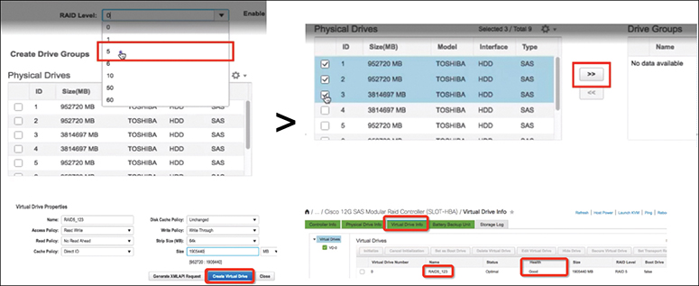
Figure 11-38 C-Series Standalone RAID Configuration
Step 5. To install any operating system (ESXi, for example), you need to map the operating system ISO image to a DVD. From the Fabric Interconnect Setup CIMC, select Launch KVM. (Ensure JRE 1.7 or higher is installed on the PC if you use a Java-based KVM.) In this case, you use an HTML-based KVM, as shown in the Figure 11-39.

Figure 11-39 C-Series Standalone KVM
Step 6. Mount the Virtual ISO with the KVM Console, as shown in Figure 11-40.
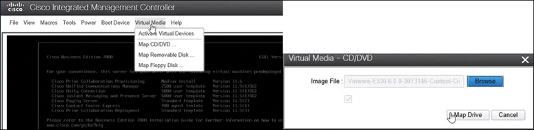
Figure 11-40 C-Series Standalone CD/DVD Mapping
Step 7. Reboot the Cisco UCS server from the KVM. Press F6 on startup, choose the Virtual CD/DVD option, and then press Enter (see Figure 11-41).

Figure 11-41 C-Series Standalone Boot OS from CD/DVD
Network Management
The Cisco UCS Fabric Interconnect behaves as a switching device between the servers and the network, and the Cisco UCS Manager is embedded in the fabric interconnect, providing server hardware state abstraction. This section covers switching and server network profile configurations.
UCS Virtual LAN
A virtual LAN (VLAN) is a switched network that is logically segmented by function, project team, or application, without regard to the physical locations of the users. VLANs have the same attributes as physical LANs, but you can group end stations even if they are not physically located on the same LAN segment.
Any switch port can belong to a VLAN. Unicast, broadcast, and multicast packets are forwarded and flooded only to end stations in the VLAN. Each VLAN is considered a logical network, and packets destined for stations that do not belong to the VLAN must be forwarded through a router or bridge.
VLANs are typically associated with IP subnetworks. For example, all of the end stations in a particular IP subnet belong to the same VLAN. To communicate between VLANs, you must route the traffic. By default, a newly created VLAN is operational. Additionally, you can configure VLANs to be in the active state, which is passing traffic, or in the suspended state, in which the VLANs are not passing packets. By default, the VLANs are in the active state and pass traffic.
You can use the Cisco UCS Manager to manage VLANs by doing the following:
• Configure named VLANs and private VLANs (PVLANs).
• Assign VLANS to an access or trunk port.
• Create, delete, and modify VLANs.
VLANs are numbered from 1 to 4094. All configured ports belong to the default VLAN when you first bring up a switch. The default VLAN (VLAN 1) uses only default values. You cannot create, delete, or suspend activity in the default VLAN.
The native VLAN and the default VLAN are not the same. Native refers to VLAN traffic without an 802.1q header and can be assigned or not. The native VLAN is the only VLAN that is not tagged in a trunk, and the frames are transmitted unchanged.
You can tag everything and not use a native VLAN throughout your network, and the VLAN or devices are reachable because switches use VLAN 1 as the native by default.
The UCS Manager - LAN Uplink Manager configuration page enables you to configure VLANs and to change the native VLAN setting. Changing the native VLAN setting requires a port flap for the change to take effect; otherwise, the port flap is continuous. When you change the native VLAN, there is a loss of connectivity for approximately 20–40 seconds.
Native VLAN guidelines are as follows:
• You can configure native VLANs only on trunk ports.
• You can change the native VLAN on a UCS vNIC; however, the port flaps and can lead to traffic interruptions.
• Cisco recommends using the native VLAN 1 setting to prevent traffic interruptions if using the Cisco Nexus 1000v switches. The native VLAN must be the same for the Nexus 1000v port profiles and your UCS vNIC definition.
• If the native VLAN 1 setting is configured, and traffic routes to an incorrect interface, there is an outage, or the switch interface flaps continuously, your disjoint Layer 2 network configuration might have incorrect settings.
• Using the native VLAN 1 for management access to all of your devices can potentially cause problems if someone connects another switch on the same VLAN as your management devices.
You configure a VLAN by assigning a number to it. You can delete VLANs or move them from the active operational state to the suspended operational state. If you attempt to create a VLAN with an existing VLAN ID, the switch goes into the VLAN sub-mode but does not create the same VLAN again. Newly created VLANs remain unused until you assign ports to the specific VLAN. All of the ports are assigned to VLAN 1 by default. Depending on the range of the VLAN, you can configure the following parameters for VLANs (except for the default VLAN):
• VLAN name
• Shut down or not shut down
When you delete a specified VLAN, the ports associated with that VLAN are shut down and no traffic flows. However, the system retains all of the VLAN-to-port mappings for that VLAN. When you re-enable or re-create the specified VLAN, the system automatically reinstates all of the original ports to that VLAN.
If a VLAN group is used on a vNIC and also on a port channel assigned to an uplink, you cannot delete and add VLANs in the same transaction. The act of deleting and adding VLANs in the same transaction causes ENM pinning failure on the vNIC. vNIC configurations are done first, so the VLAN is deleted from the vNIC and a new VLAN is added, but this VLAN is not yet configured on the uplink. Hence, the transaction causes a pinning failure. You must add and delete a VLAN from a VLAN group in separate transactions.
Access ports only send untagged frames and belong to and carry the traffic of only one VLAN. Traffic is received and sent in native formats with no VLAN tagging. Anything arriving on an access port is assumed to belong to the VLAN assigned to the port.
You can configure a port in access mode and specify the VLAN to carry the traffic for that interface. If you do not configure the VLAN for a port in access mode or an access port, the interface carries the traffic for the default VLAN, which is VLAN 1.
You can change the access port membership in a VLAN by configuring it. You must create the VLAN before you can assign it as an access VLAN for an access port. If you change the access VLAN on an access port to a VLAN that is not yet created, the Cisco UCS Manager shuts down that access port.
If an access port receives a packet with an 802.1Q tag in the header other than the access VLAN value, that port drops the packet without learning its MAC source address. If you assign an access VLAN that is also a primary VLAN for a private VLAN, all access ports with that access VLAN receive all the broadcast traffic for the primary VLAN in the private VLAN mode.
Trunk ports allow multiple VLANs to transport between switches over that trunk link. A trunk port can carry untagged packets simultaneously with the 802.1Q tagged packets. When you assign a default port VLAN ID to the trunk port, all untagged traffic travels on the default port VLAN ID for the trunk port, and all untagged traffic is assumed to belong to this VLAN. This VLAN is referred to as the native VLAN ID for a trunk port. The native VLAN ID is the VLAN that carries untagged traffic on trunk ports.
The trunk port sends an egressing packet with a VLAN that is equal to the default port VLAN ID as untagged; all the other egressing packets are tagged by the trunk port. If you do not configure a native VLAN ID, the trunk port uses the default VLAN.
Note
Changing the native VLAN on a trunk port or an access VLAN of an access port flaps the switch interface.
![]()
Named VLANs
The name that you assign to a VLAN ID adds a layer of abstraction that allows you to globally update all servers associated with service profiles that use the named VLAN. You do not need to reconfigure the servers individually to maintain communication with the external LAN.
You can create more than one named VLAN with the same VLAN ID. For example, if servers that host business services for Human Resources and Finance need to access the same external LAN, you can create VLANs named HR and Finance with the same VLAN ID. Then, if the network is reconfigured and Finance is assigned to a different LAN, you only have to change the VLAN ID for the named VLAN for Finance.
In a cluster configuration, you can configure a named VLAN to be accessible only to one fabric interconnect or to both fabric interconnects.
Note
You cannot create VLANs with IDs from 3915 to 4042. These ranges of VLAN IDs are reserved. The VLAN IDs you specify must also be supported on the switch that you are using. For example, on Cisco Nexus 5000 Series switches, the VLAN ID range from 3968 to 4029 is reserved. Before you specify the VLAN IDs in the Cisco UCS Manager, make sure that the same VLAN IDs are available on your switch.
Note
VLAN 4048 is user configurable. However, the Cisco UCS Manager uses VLAN 4048 for the following default values. If you want to assign 4048 to a VLAN, you need to change the FCoE default VLAN. The FCoE VLAN for the default VSAN uses VLAN 4048 by default. The FCoE storage port native VLAN uses VLAN 4049.
The VLAN name is case sensitive. The following types of ports are counted in the VLAN port calculation:
• Border uplink Ethernet ports
• Border uplink Ether-channel member ports
• FCoE ports in a SAN cloud
• Ethernet ports in a NAS cloud
• Static and dynamic vNICs created through service profiles
• VM vNICs created as part of a port profile in a hypervisor in hypervisor domain
Based on the number of VLANs configured for these ports, the Cisco UCS Manager tracks the cumulative count of VLAN port instances and enforces the VLAN port limit during validation. The Cisco UCS Manager reserves some predefined VLAN port resources for control traffic. These include management VLANs configured under HIF and NIF ports.
The Cisco UCS Manager validates VLAN port availability during the following operations:
• Configuring and unconfiguring border ports and border port channels.
• Adding or removing VLANs from a cloud.
• Configuring or unconfiguring SAN or NAS ports.
• Associating or disassociating service profiles that contain configuration changes.
• Configuring or unconfiguring VLANs under vNICs or vHBAs.
• Receiving creation or deletion notifications from a VMWare vNIC and from an ESX hypervisor.
• Fabric interconnect reboot.
• Cisco UCS Manager upgrade or downgrade.
The Cisco UCS Manager strictly enforces the VLAN port limit on service profile operations. If the Cisco UCS Manager detects that the VLAN port limit is exceeded, the service profile configuration fails during deployment.
Exceeding the VLAN port count in a border domain is less disruptive. When the VLAN port count is exceeded in a border domain, the Cisco UCS Manager changes the allocation status to Exceeded. To change the status back to Available, complete one of the following actions:
• Unconfigure one or more border ports.
• Remove VLANs from the LAN cloud.
• Unconfigure one or more vNICs or vHBAs.
Use the following steps to configure named VLANs:
Step 1. In the Navigation pane, click LAN.
Step 2. On the LAN tab, click the LAN node. Then in the Work pane, click the VLANs tab. On the icon bar to the right of the table, click + (the plus sign). If the + icon is disabled, click an entry in the table to enable it.
Step 3. In the Create VLANs dialog box, as shown in Figure 11-42.


Figure 11-42 Name VLAN Configuration
Step 4. If you clicked the Check Overlap button, do the following:
• Click the Overlapping VLANs tab and review the fields to verify that the VLAN ID does not overlap with any IDs assigned to existing VLANs.
• Click the Overlapping VSANs tab and review the fields to verify that the VLAN ID does not overlap with any FCoE VLAN IDs assigned to existing VSANs.
• Click OK.
• If the Cisco UCS Manager identified any overlapping VLAN IDs or FCoE VLAN IDs, change the VLAN ID to one that does not overlap with an existing VLAN.
Step 7. Click OK.
The Cisco UCS Manager adds the VLAN to one of the following VLANs nodes:
• The LAN Cloud > VLANs node for a VLAN accessible to both fabric interconnects.
• The Fabric_Interconnect_Name > VLANs node for a VLAN accessible to only one fabric interconnect.
Use the following steps to delete named VLANs:
Step 1. In the Navigation pane, click LAN. Then on the LAN tab, click the LAN node. In the Work pane, click the VLANs tab.
Step 2. Click one of the following subtabs, based on the VLAN that you want to delete (see Figure 11-43).


Figure 11-43 Deleting a Named VLAN
Step 3. In the table, click the VLAN that you want to delete. You can use the Shift key or Ctrl key to select multiple entries.
Step 4. Right-click the highlighted VLAN or VLANs and click Delete. If a confirmation dialog box is displayed, click Yes.
Note
If the Cisco UCS Manager includes a named VLAN with the same VLAN ID as the one you delete, the VLAN is not removed from the fabric interconnect configuration until all named VLANs with that ID are deleted.
Note
If you are deleting a private primary VLAN, ensure that you reassign the secondary VLANs to another working primary VLAN.
Note
Before you delete a VLAN from a fabric interconnect, ensure that the VLAN was removed from all vNICs and vNIC templates. If you delete a VLAN that is assigned to a vNIC or vNIC template, the vNIC might allow that VLAN to flap.
![]()
Private VLANs
A private VLAN (PVLAN) partitions the Ethernet broadcast domain of a VLAN into subdomains and allows you to isolate some ports. Each subdomain in a PVLAN includes a primary VLAN and one or more secondary VLANs. All secondary VLANs in a PVLAN must share the same primary VLAN. The secondary VLAN ID differentiates one subdomain from another. All secondary VLANs in a Cisco UCS domain can be isolated or community VLANs.
Note
You cannot configure an isolated VLAN to use with a regular VLAN.
Communications on an isolated VLAN can use only the associated port in the primary VLAN. These ports are isolated ports and are not configurable in the Cisco UCS Manager. A primary VLAN can have only one isolated VLAN, but multiple isolated ports on the same isolated VLAN are allowed. These isolated ports cannot communicate with each other. The isolated ports can communicate only with a regular trunk port or promiscuous port that allows the isolated VLAN.
An isolated port is a host port that belongs to an isolated secondary VLAN. This port has complete isolation from other ports within the same private VLAN domain. PVLANs block all traffic to isolated ports except traffic from promiscuous ports. Traffic received from an isolated port is forwarded only to promiscuous ports. You can have more than one isolated port in a specified isolated VLAN. Each port is completely isolated from all other ports in the isolated VLAN.
Community ports communicate with each other and with promiscuous ports. Community ports have Layer 2 isolation from all other ports in other communities. A promiscuous port can communicate with all interfaces.
When you create PVLANs, use the following guidelines:
• The uplink Ethernet port channel cannot be in promiscuous mode.
• Each primary VLAN can have only one isolated VLAN.
• VIFs on VNTAG adapters can have only one isolated VLAN.
![]()
UCS Identity Pools
The Cisco UCS Manager can classify servers into resource pools based on criteria including physical attributes (such as processor, memory, and disk capacity) and location (for example, blade chassis slot). Server pools can help automate configuration by identifying servers that can be configured to assume a particular role (such as web server or database server) and automatically configuring them when they are added to a pool.
Resource pools are collections of logical resources that can be accessed when configuring a server. These resources include universally unique IDs (UUIDs), MAC addresses, and WWNs.
The Cisco UCS platform utilizes a dynamic identity instead of hardware burned-in identities. A unique identity is assigned from identity and resource pools. Computers and peripherals extract these identities from service profiles. A service profile has all the server identities including UUIDs, MACs, WWNNs, firmware versions, BIOS settings, policies, and other server settings. A service profile is associated with the physical server that assigns all the settings in a service profile to the physical server.
In case of server failure, the failed server needs to be removed and the replacement server needs to be associated with the existing service profile of the failed server. In this service profile association process, the new server automatically picks up all the identities of the failed server, and the operating system or applications that depend on these identities do not observe any change in the hardware. In case of peripheral failure, the replacement peripheral automatically acquires the identities of the failed components. This significantly improves the system recovery time in case of a failure. Server profiles include many identity pools:
• UUID suffix pools
• MAC pools
• IP pools
• Server pools
Universally Unique Identifier Suffix Pools
A universally unique identifier suffix pool is a collection of System Management BIOS (SMBIOS) UUIDs that are available to be assigned to servers. The first number of digits that constitute the prefix of the UUID is fixed. The remaining digits, the UUID suffix, are variable. A UUID suffix pool ensures that these variable values are unique for each server associated with a service profile which uses that particular pool to avoid conflicts.
If you use UUID suffix pools in service profiles, you do not have to manually configure the UUID of the server associated with the service profile.
An example of creating UUID pools is as follows:
Step 1. In the Navigation pane, click Servers.
Step 2. Expand Servers > Pools.
Step 3. Expand the node for the organization where you want to create the pool. If the system does not include multitenancy, expand the root node.
Step 4. Right-click UUID Suffix Pools and select Create UUID Suffix Pool.
Step 5. In the Define Name and Description page of the Create UUID Suffix Pool wizard, complete the following fields (see Figure 11-44).

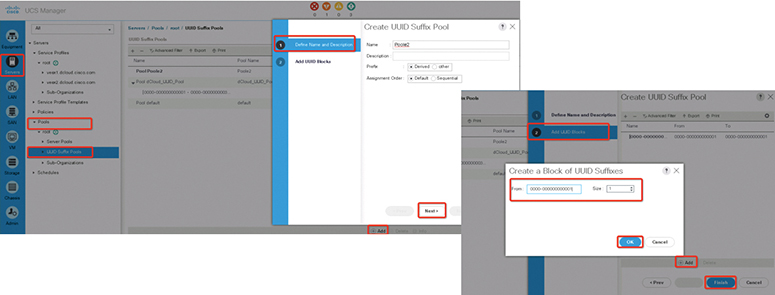
Figure 11-44 Creating UUID Suffix Pool
Step 6. Click Next.
Step 7. In the Add UUID Blocks page of the Create UUID Suffix Pool wizard, click Add.
Step 8. In the Create a Block of UUID Suffixes dialog box, complete the following fields:

Step 9. Click OK.
Step 10. Click Finish to complete the wizard.
You need to assign the UUID suffix pool to a service profile and/or template.
MAC Pools
A MAC pool is a collection of network identities, or MAC addresses, that are unique in their Layer 2 environment and are available to be assigned to vNICs on a server. If you use MAC pools in service profiles, you do not have to manually configure the MAC addresses to be used by the server associated with the service profile.
In a system that implements multitenancy, you can use the organizational hierarchy to ensure that MAC pools can only be used by specific applications or business services. The Cisco UCS Manager uses the name resolution policy to assign MAC addresses from the pool. To assign a MAC address to a server, you must include the MAC pool in a vNIC policy. The vNIC policy is then included in the service profile assigned to that server. You can specify your own MAC addresses or use a group of MAC addresses provided by Cisco.
An example of creating a Management IP pool is as follows:
Step 1. In the Navigation pane, click the LAN tab. In the LAN tab, expand LAN > Pools and then expand the node for the organization where you want to create the pool. If the system does not include multitenancy, expand the root node.
Step 2. Right-click MAC Pools and select Create MAC Pool.
Step 3. In the first page of the Create MAC Pool wizard, do the following:
• Enter a unique name and description for the MAC Pool.
• Click Next.
Step 4. In the second page of the Create MAC Pool wizard, do the following:
• Click Add.
• In the Create a Block of MAC Addresses page, enter the first MAC address in the pool and the number of MAC addresses to include in the pool.
• Click OK.
• Click Finish.
IP Pools
IP pools are collections of IP addresses that do not have a default purpose. You can create IPv4 or IPv6 address pools in the Cisco UCS Manager to do the following:
• Replace the default management IP pool ext-mgmt for servers that have an associated service profile. The Cisco UCS Manager reserves each block of IP addresses in the IP pool for external access that terminates in the Cisco Integrated Management Controller (CIMC) on a server. If there is no associated service profile, you must use the ext-mgmt IP pool for the CIMC to get an IP address.
• Replace the management in-band or out-of-band IP addresses for the CIMC.
Note
You cannot create iSCSI boot IPv6 pools in the Cisco UCS Manager.
You can create IPv4 address pools in the Cisco UCS Manager to do the following:
• Replace the default iSCSI boot IP pool iscsi-initiator-pool. The Cisco UCS Manager reserves each block of IP addresses in the IP pool that you specify.
• Replace both the management IP address and iSCSI boot IP addresses.
Note
The IP pool must not contain any IP addresses that were assigned as static IP addresses for a server or service profile.
An example of creating a management IP pool is as follows:
Step 1. In the Navigation pane, click the LAN tab. In the LAN tab, expand LAN > Pools > Organization_Name.
Step 2. Right-click IP Pools and select Create IP Pool.
Step 3. In the Define Name and Description page of the Create IP Pool wizard, complete the following fields:

Step 4. Click Next.
Step 5. In the Add IPv4 Blocks page of the Create IP Pool wizard, click Add.
Step 6. In the Create a Block of IPv4 Addresses dialog box, complete the following fields (see Figure 11-45).

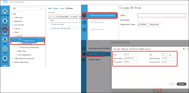
Figure 11-45 Creating an IP Pool
Step 7. Click Next.
Step 8. In the Add IPv6 Blocks page of the Create IP Pool wizard, click Add.
Step 9. In the Create a Block of IPv6 Addresses dialog box, complete the following fields.

Step 10. Click OK, and then click Finish to complete the wizard.
Server Pools
A server pool contains a set of servers. These servers typically share the same characteristics. Those characteristics can be their location in the chassis or an attribute such as server type, amount of memory, local storage, type of CPU, or local drive configuration. You can manually assign a server to a server pool, or you can use server pool policies and server pool policy qualifications to automate the assignment.
If your system implements multitenancy through organizations, you can designate one or more server pools to be used by a specific organization. For example, a pool that includes all servers with two CPUs could be assigned to the Marketing organization, while all servers with 64-GB memory could be assigned to the Finance organization. A server pool can include servers from any chassis in the system, and a given server can belong to multiple server pools.
Note
The Cisco UCS Director displays only the managed servers in a server pool, but the size of the pool includes all servers. For example, if a server pool contains two servers and only one server is managed by the Cisco UCS Director, all server pool reports and actions on that pool display only one (managed) server. However, the pool size is displayed as two.
An example of creating a server pool is as follows:
Step 1. On the menu bar, choose Physical > Compute.
Step 2. In the left pane, expand the pod and then click the Cisco UCS Manager account.
Step 3. In the right pane, click the Organizations tab.
Step 4. Click the organization in which you want to create the pool and then click View Details.
Step 5. Click the Server Pools tab and then click Add.
Step 6. In the Add Server Pool dialog box, add a name and description for the pool.
Step 7. (Optional) In the Servers field, do the following to add servers to the pool:
• Click Select.
• On the Select Items page, click the check boxes for the servers that you want to add to the pool.
• Click Select.
Step 8. Click Add.
The following steps show how to assign a server pool to a Cisco UCS Director Group:
Step 1. On the menu bar, choose Physical > Compute.
Step 2. In the left pane, expand the pod and then click the Cisco UCS Manager account.
Step 3. In the right pane, click the Organizations tab.
Step 4. Click the organization that contains the pool you want to assign, and then click View Details.
Step 5. Click the Server Pools tab.
Step 6. Click the row in the table for the pool that you want to assign to a Cisco UCS Director group.
Step 7. Click Assign Group.
Step 8. In the Select Group dialog box, do the following:
• From the Group drop-down list, choose the Cisco UCS Director group to which you want to assign this server pool.
• In the Label field, enter a label to identify this server pool.
• Click Submit.
Service Profiles
Every server that is provisioned in the Cisco Unified Computing System is specified by a service profile. A service profile is a software definition of a server and its LAN and SAN network connectivity; in other words, a service profile defines a single server and its storage and networking characteristics. Service profiles are stored in the Cisco UCS Fabric Interconnects. When a service profile is deployed to a server, the Cisco UCS Manager automatically configures the server, adapters, Fabric Extenders, and fabric interconnects to match the configuration specified in the service profile. This automation of device configuration reduces the number of manual steps required to configure servers, network interface cards, host bus adapters, and LAN and SAN switches.
A service profile typically includes four types of information:
1. Server definition: It defines the resources (for example, a specific server or a blade inserted to a specific chassis) that are required to apply to the profile.
2. Identity information: Identity information includes the UUID, MAC address for each virtual NIC (vNIC), and WWN specifications for each HBA.
3. Firmware revision specifications: These are used when a certain tested firmware revision is required to be installed or for some other reason a specific firmware is used.
4. Connectivity definition: It is used to configure network adapters, Fabric Extenders, and parent interconnects; however, this information is abstract because it does not include the details of how each network component is configured.
A service profile is created by the Cisco UCS server administrator. This service profile leverages configuration policies that were created by the server, network, and storage administrators. Server administrators can also create a service profile template that can be used later to create service profiles in an easier way. A service template can be derived from a service profile, with server and I/O interface identity information abstracted. Instead of specifying exact UUID, MAC address, and WWN values, a service template specifies where to get these values. For example, a service profile template might specify the standard network connectivity for a web server and the pool from which its interface’s MAC addresses can be obtained. Service profile templates can be used to provision many servers with the same simplicity as creating a single one.
There are two types of service profiles in a UCS system:
• Service profiles that inherit server identity: These service profiles are similar in concept to a rack-mounted server. These service profiles use the burned-in values (such as MAC addresses, WWN addresses, BIOS version and settings) of the hardware. Due to the nature of using these burned-in values, these profiles are not easily portable and can’t be used for moving from one server to the other. In other words, these profiles exhibit the nature of 1:1 mapping and thus require changes to be made to them when moving from one server to another.
• Service profiles that override server identity: These service policies exhibit the nature of stateless computing in the Cisco UCS system. These service profiles take the resources (such as MAC addresses, WWN addresses, BIOS version) from a resource pool already created in the Cisco UCS Manager. The settings or values from these resource pools override the burned-in values of the hardware. Hence, these profiles are very flexible and can be moved from one server to the other easily, and this movement is transparent to the network. In other words, these profiles provide a one-to-many mapping and require no change to be made to them when moving from one server to another.
To create a service profile, navigate to the Servers tab, right-click Service Profiles, and choose Create Service Profile, as shown in Figure 11-46.
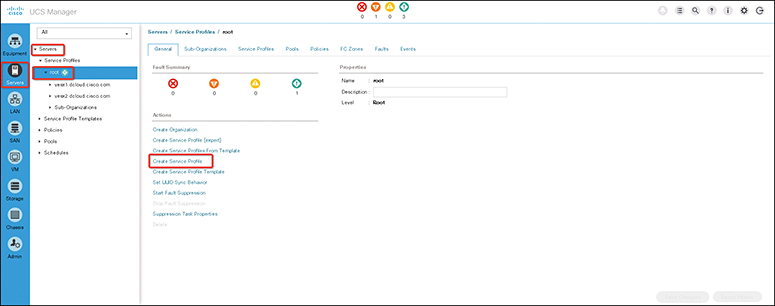
Figure 11-46 Creating a Service Profile
The vNIC creation for servers is part of the server profile or server profile template creation. After a service profile (Expert) is started for the blade servers, creating the vNIC is the second step in the configuration wizard.
Using a vNIC template is the recommended method for configuring the NIC settings once, for each template, and then quickly creating new vNICs with the desired configuration. The vNIC configuration settings can be optimized for various operating systems, storage devices, and hypervisors. A vNIC template can be configured as either of the following:
• Initiating template: This vNIC template provides one-time configuration for the vNICs created using this template. Any subsequent changes to the template are not propagated to abstracted vNICs.
• Updating template: This vNIC template provides initial configuration for the vNICs created using this template. Any subsequent changes to the template are also propagated to abstracted vNICs. It is a good practice to create a vNIC template for production environments.
vNIC MAC addresses can be assigned manually or by configuring a MAC address pool. It is possible to either use the burned-in MAC addresses or abstract MAC addresses from an identity pool with system-defined prefixes. Stateless computing is the salient feature of the Cisco UCS platform. Therefore, it is a good practice to abstract vNIC MAC addresses for server profiles and consequently use server vNIC MAC addresses from MAC address identity pools instead of using burned-in NIC MAC addresses. The benefit of abstracting the MAC identity is that in case of physical server failure, the server profile can be easily associated with the replacement server. The new server acquires all the identities associated with the old server, including the vNIC MAC addresses. From the operating system perspective, there is no change at all.
A good exercise is to create vNIC templates with different configurations and create individual vNICs from vNIC templates as required. Also, you can define MAC address pools and assign MAC addresses to individual vNICs using those MAC address pools.
A vNIC is typically abstracted from the physical mezzanine card. The Cisco mezzanine NIC card, also known as a Palo card or virtual interface card (VIC), provides dynamic server interfaces. Cisco VIC cards provide up to 256 dynamic interfaces. vNICs can be created within server profiles or by using a vNIC template. Using a vNIC template is the recommended method for configuring the NIC settings, doing so once for each template and then quickly creating additional vNICs with the desired configurations. The vNIC configuration settings can be optimized for various operating systems, storage devices, and hypervisors.
![]()
UCS Server Policies
The Cisco UCS Manager uses server policies to assign settings and to define behavior of several server components. These policies include BIOS policies, boot policies, host firmware policies, maintenance policies, local disk policies, power control polices, scrub policies, vNIC/vHBA placement policies, and so on, as shown in Figure 11-47.
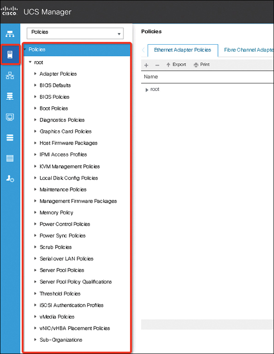
Figure 11-47 UCS Server Policies List
• BIOS policy: The Cisco UCS provides two methods for making global modifications to the BIOS settings on servers in a Cisco UCS domain.
• You can create one or more BIOS policies that include a specific grouping of BIOS settings that match the needs of a server or set of servers.
• You can use the default BIOS settings for a specific server platform.
Both the BIOS policy and the default BIOS settings for a server platform enable you to fine-tune the BIOS settings for a server managed by the Cisco UCS Manager.
Depending on the needs of the data center, you can configure BIOS policies for some service profiles and use the BIOS defaults in other service profiles in the same Cisco UCS domain, or you can use only one of them. You can also use the Cisco UCS Manager to view the actual BIOS settings on a server and determine whether they are meeting current needs. BIOS policies include
• Main BIOS Settings
• Processor BIOS Settings
• Intel Directed I/O BIOS Settings
• RAS Memory BIOS Settings
• Serial Port BIOS Settings
• USB BIOS Settings
• PCI Configuration BIOS Settings
• QPI BIOS Settings
• LOM and PCIe Slots BIOS Settings
• Graphics Configuration BIOS Settings
• Boot Options BIOS Settings
• Server Management BIOS Settings
Note
The Cisco UCS Manager pushes BIOS configuration changes through a BIOS policy or default BIOS settings to the CIMC buffer. These changes remain in the buffer and do not take effect until the server is rebooted. We recommend that you verify the support for BIOS settings in the server that you want to configure. Some settings, such as Mirroring mode for RAS Memory, are not supported by all Cisco UCS servers.
• Boot policy: The Cisco UCS Manager boot policy overrides the boot order in the BIOS setup menu and determines the following:
• Selection of the boot device
• Location from which the server boots
• Order in which boot devices are invoked
For example, you can choose to have associated servers boot from a local device, such as a local disk or CD-ROM (VMedia), or you can select a SAN boot or a LAN (PXE) boot. You must include this policy in a service profile, and that service profile must be associated with a server for it to take effect. If you do not include a boot policy in a service profile, the Cisco UCS Manager applies the default boot policy.
Note
Changes to a boot policy might be propagated to all servers created with an updating service profile template that includes that boot policy. Reassociation of the service profile with the server to rewrite the boot order information in the BIOS is automatically triggered.
• Host firmware policies: Use host firmware policy to associate qualified or well-known versions of the BIOS, adapter ROM, or local disk controller with logical service profiles, as described earlier. A best practice is to create one policy, based on the latest packages that correspond with the Cisco UCS Manager infrastructure and server software release, and to reference that host firmware package for all service profiles and templates created. This best practice helps ensure version consistency of a server’s lowest-level firmware, regardless of physical server failures that may cause reassociation of service profiles on other blades.
![]()
• Maintenance policy: Use the maintenance policy to specify how the Cisco UCS Manager should proceed for configuration changes that will have a service impact or require a server reboot. Values for the maintenance policy can be “immediate,” “userack,” or “timer automatic.” The best practice is to not use the “default” policy and instead to create and use maintenance policies for either “user-ack” or “timer automatic,” and to always have these as elements of the service profile or service profile template definition.
![]()
• Power control policy: The Cisco UCS uses the priority set in the power control policy along with the blade type and configuration to calculate the initial power allocation for each blade within a chassis. During normal operation, the active blades within a chassis can borrow power from idle blades within the same chassis. If all blades are active and reach the power cap, service profiles with higher priority power control policies take precedence over service profiles with lower priority power control policies.
Priority is ranked on a scale of 1 to 10, where 1 indicates the highest priority and 10 indicates lowest priority. The default priority is 5.
For mission-critical applications, a special priority called no-cap is also available. Setting the priority to no-cap prevents the Cisco UCS from leveraging unused power from a particular server. With this setting, the server is allocated the maximum amount of power possible for that type of server.
• Local disk policies: A local disk policy specifies how to configure any local disks on the blade. A best practice is to specify no local storage for SAN boot environments, thereby precluding any problems at service profile association time, when local disks may present themselves to the host OS during installation. You can also remove or unseat local disks from blades completely, especially blades used for OS installation.
• Scrub policies: A scrub policy determines what happens to local disks and the BIOS upon service profile disassociation. The default policy is no scrubbing. A best practice is to set the policy to scrub the local disk, especially for service providers, multitenant customers, and environments in which network installation to a local disk is used.
• vNIC/vHBA placement policies: vNIC/vHBA placement policies are used to determine what types of vNICs or vHBAs can be assigned to the physical adapters on a server. Each vNIC/vHBA placement policy contains four virtual network interface connections (vCons) that are virtual representations of the physical adapters. When a vNIC/vHBA placement policy is assigned to a service profile, and the service profile is associated with a server, the vCons in the vNIC/vHBA placement policy are assigned to the physical adapters.
If you do not include a vNIC/vHBA placement policy in the service profile or you use the default configuration for a server with two adapters, the Cisco UCS Manager defaults to the All configuration and equally distributes the vNICs and vHBAs between the adapters.
You can use this policy to assign vNICs or vHBAs to either of the two vCons. The Cisco UCS Manager uses the vCon assignment to determine how to assign the vNICs and vHBAs to the physical adapter during service profile association.
• All: All configured vNICs and vHBAs can be assigned to the vCon, whether they are explicitly assigned to it, unassigned, or dynamic.
• Assigned Only: vNICs and vHBAs must be explicitly assigned to the vCon. You can assign them explicitly through the service profile or the properties of the vNIC or vHBA.
• Exclude Dynamic: Dynamic vNICs and vHBAs cannot be assigned to the vCon. The vCon can be used for all static vNICs and vHBAs, whether they are unassigned or explicitly assigned to it.
• Exclude Unassigned: Unassigned vNICs and vHBAs cannot be assigned to the vCon. The vCon can be used for dynamic vNICs and vHBAs and for static vNICs and vHBAs that are explicitly assigned to it.
UCS Service Profile Templates
With a service profile template, you can quickly create several service profiles with the same basic parameters, such as the number of vNICs and vHBAs, and with identity information drawn from the same pools.
For example, if you need several service profiles with similar values to configure servers to host database software, you can create a service profile template, either manually or from an existing service profile. You then use the template to create the service profiles. The Cisco UCS supports the following types of service profile templates:
• Initial template: Service profiles created from an initial template inherit all the properties of the template. However, after you create the profile, it is no longer connected to the template. If you need to make changes to one or more profiles created from this template, you must change each profile individually.
• Updating template: Service profiles created from an updating template inherit all the properties of the template and remain connected to the template. Any changes to the template automatically update the service profiles created from the template.
Service profile templates created in Cisco UCS Central can be used on any of your registered Cisco UCS domains. The following steps show how to create a service profile template:
Step 1. In the Navigation pane, click the Servers tab.
Step 2. On the Servers tab, expand Servers > Service Profiles.
Step 3. Expand the node for the organization where you want to create the service profile. If the system does not include multitenancy, expand the root node.
Step 4. Right-click the organization and select Create Service Profile (Expert), as shown in Figure 11-48.

Figure 11-48 Creating a Service Profile Template
Step 5. In the Create Service Profile (expert) wizard, complete the following:
Page 1: Identifying the Service Profile, as in Figure 11-49.
Page 2: Configuring the Storage Options, as in Figure 11-50.
Page 3: Configuring the Networking Options, as in Figure 11-51.
Page 4: Setting the vNIC/vHBA Placement, as in Figure 11-52.
Page 5: Setting the Server Boot Order, as in Figure 11-53.
Page 6: Adding the Maintenance Policy, as in Figure 11-54.
Page 7: Specifying the Server Assignment, as in Figure 11-55.
Page 8: Adding Operational Policies, as in Figure 11-56.

Figure 11-49 Service Profile Template Wizard page 1

Figure 11-50 Service Profile Template Wizard page 2
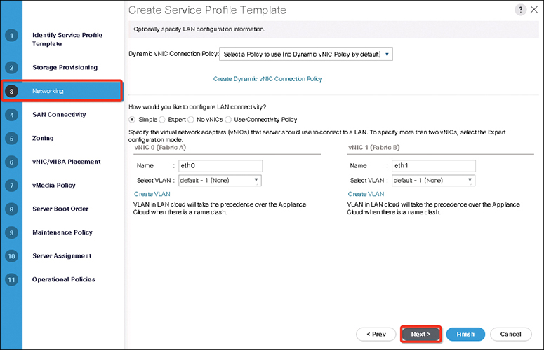
Figure 11-51 Service Profile Template Wizard page 3
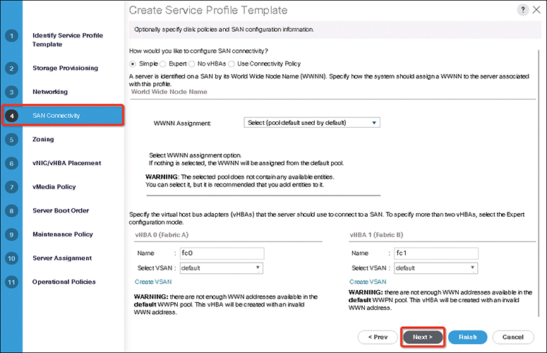
Figure 11-52 Service Profile Template Wizard page 4
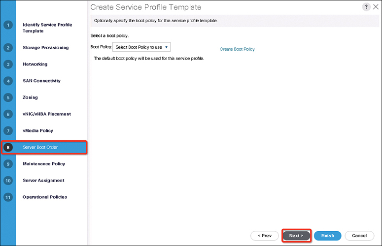
Figure 11-53 Service Profile Template Wizard page 5
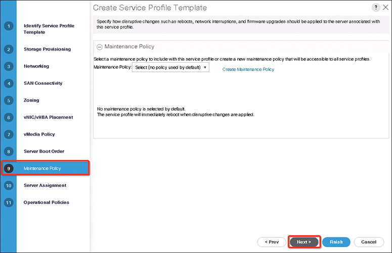
Figure 11-54 Service Profile Template Wizard page 6
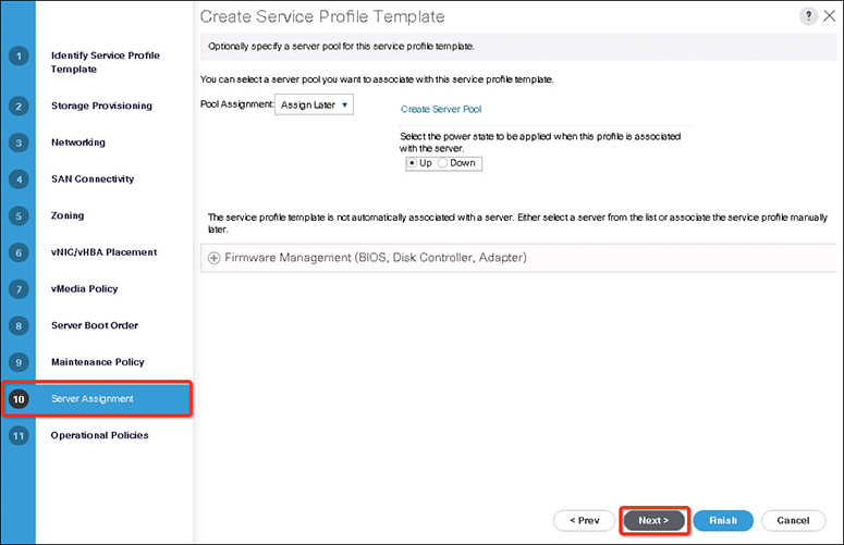
Figure 11-55 Service Profile Template Wizard page 7

Figure 11-56 Service Profile Template Wizard page 8
Quality of Service
The Cisco UCS provides the following methods to implement quality of service:
• System classes that specify the global configuration for certain types of traffic across the entire system
• QoS policies that assign system classes for individual vNICs
• Flow control policies that determine how uplink Ethernet ports handle pause frames
Global QoS changes made to the QoS system class may result in brief data-plane interruptions for all traffic. Some examples of such changes are
• Changing the MTU size for an enabled class.
• Changing packet drop for an enabled class.
• Changing the class of service (CoS) value for an enabled class.
![]()
QoS System Classes
The Cisco UCS uses Data Center Ethernet (DCE) to handle all traffic inside a Cisco UCS domain. This industry standard enhancement to Ethernet divides the bandwidth of the Ethernet pipe into eight virtual lanes. Two virtual lanes are reserved for internal system and management traffic, and you can configure QoS for the other six virtual lanes.
System classes determine how the DCE bandwidth in these six virtual lanes is allocated across the entire Cisco UCS domain. Each system class reserves a specific segment of the bandwidth for a specific type of traffic, which provides a level of traffic management, even in an oversubscribed system. For example, you can configure the Fibre Channel Priority system class to determine the percentage of DCE bandwidth allocated to FCoE traffic. Table 11-5 describes the system classes that you can configure.
Table 11-5 UCS System QoS Class

QoS System Classes Configurations
The type of adapter in a server might limit the maximum MTU supported. For example, network MTU above the maximums might cause the packet to drop for some adapters.
Note
Under the network QoS policy, the MTU is used only for buffer carving when no-drop classes are configured. No additional MTU adjustments are required under the network QoS policy to support jumbo MTU.
You need to use the same CoS values on UCS and Nexus 5000 for all the no-drop policies. To ensure that end-to-end priority-based flow control (PFC) works correctly, have the same QoS policy configured on all intermediate switches.
An example of configuring and enabling LAN QoS is as follows:
Step 1. In the Navigation pane, click LAN. Expand LAN > LAN Cloud.
Step 2. Select the QoS System Class node. The packet drop should be unchecked to configure MTU. MTU is not configurable for drop-type QoS system classes and is always set to 9216. MTU is only configurable for no-drop-type QoS system classes.
Step 3. In the Work pane, click the General tab. Update the properties for the system class that you want to configure to meet the traffic management needs of the system.
Step 4. (Optional) To enable the system class, check the Enabled check box for the QoS system that you want to enable. Then click Save Changes (see Figure 11-57).
Note
Some properties might not be configurable for all system classes. The maximum value for MTU is 9216.
Note
The Best Effort or Fibre Channel system classes are enabled by default. You cannot disable these two system classes. All QoS policies that are associated with a disabled system class default to Best Effort or, if the disabled system class is configured with a CoS of 0, to the CoS 0 system class.
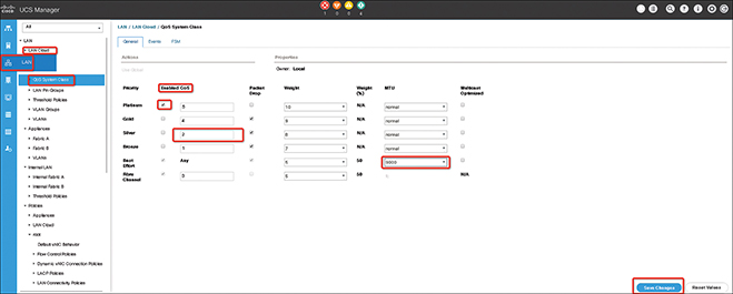
Figure 11-57 UCS LAN QoS System Class Configuration
Configuring Quality of Service Policies
A QoS policy assigns a system class to the outgoing traffic for a vNIC or vHBA. This system class determines the quality of service for that traffic. For certain adapters, you can also specify additional controls on the outgoing traffic, such as burst and rate.
You must include a QoS policy in a vNIC policy or vHBA policy and then include that policy in a service profile to configure the vNIC or vHBA.
The following steps show how to create a QoS policy:
Step 1. In the Navigation pane, click LAN. Next, expand LAN > Policies. Then expand the node for the organization where you want to create the pool. If the system does not include multitenancy, expand the root node.
Step 2. Right-click QoS Policy and select Create QoS Policy. In the Create QoS Policy dialog box, complete the required fields, as shown in Figure 11-58. Then click OK. Include the QoS policy in a vNIC or vHBA template.


Figure 11-58 UCS LAN QoS Policy Configuration
UCS Storage
The Cisco UCS support storage types are as follows:
• Direct-attached storage (DAS): This is the storage available inside a server and is directly connected to the system through the motherboard within a parallel SCSI implementation. DAS is commonly described as captive storage. Devices in a captive storage topology do not have direct access to the storage network and do not support efficient sharing of storage. To access data with DAS, you must go through a front-end network. DAS devices provide little or no mobility to other servers and little scalability.
DAS devices limit file sharing and can be complex to implement and manage. For example, to support data backups, DAS devices require resources on the host and spare disk systems that other systems cannot use. The cost and performance of this storage depend on the disks and RAID controller cards inside the servers. DAS is less expensive and is simple to configure; however, it lacks the scalability, performance, and advanced features provided by high-end storage.
• Network-attached storage (NAS): This storage is usually an appliance providing file system access. This storage could be as simple as a Network File System (NFS) or Common Internet File System (CIFS) share available to the servers. Typical NAS devices are cost-effective devices that do not provide very high performance but have very high capacity with some redundancy for reliability. NAS is usually moderately expensive and simple to configure; plus it provides some advanced features. However, it also lacks scalability, performance, and advanced features provided by SAN.
• Storage-area network (SAN): A SAN is a specialized high-speed network that attaches servers and storage devices. A SAN allows an any-to-any connection across the network by using interconnect elements, such as switches and directors. It eliminates the traditional dedicated connection between a server and storage, and the concept that the server effectively owns and manages the storage devices. It also eliminates any restriction to the amount of data that a server can access, currently limited by the number of storage devices that are attached to the individual server. Instead, a SAN introduces the flexibility of networking to enable one server or many heterogeneous servers to share a common storage utility. A network might include many storage devices, including disk, tape, and optical storage. Additionally, the storage utility might be located far from the servers that it uses. This type of storage provides maximum reliability, expandability, and performance. The cost of SAN is also very high compared to other storage options. A SAN is the most resilient, highly scalable, and high-performance storage; however, it is also the most expensive and complex to manage.
![]()
UCS SAN Connectivity
The Cisco Unified Computing System model supports different methods to connect to centralized storage. The first storage connectivity method uses a pure Ethernet IP network to connect the servers to both their user community and the shared storage array. Communication between the servers and storage over IP can be accomplished by using a Small Computer System Interface over IP (iSCSI), which is a block-oriented protocol encapsulated over IP, or traditional network-attached storage (NAS) protocols such as Common Internet File System (CIFS) or Network File System (NFS). LAN-based storage access follows the path through the Cisco Nexus 5500 Series Switching Fabric shown in Figure 11-59. A more traditional but advanced second method is using a Fibre Channel SAN using the Data Center Core Cisco Nexus 5500UP switches or the Cisco MDS Series for larger SAN environments. Fibre Channel over Ethernet (FCoE) builds on the lossless Ethernet infrastructure to provide a converged network infrastructure.
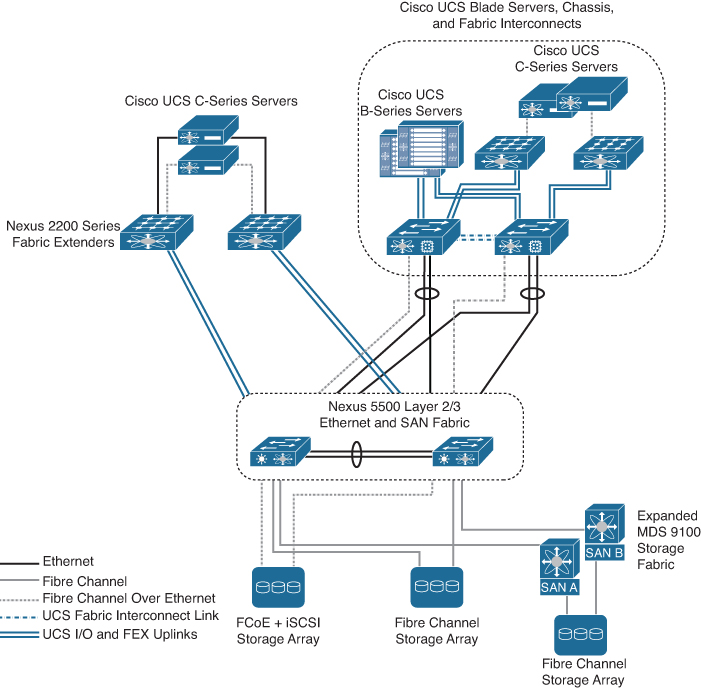
Figure 11-59 LAN-Based Storage
For resilient access, SANs are normally built with two distinct fabric switches that are not cross connected. Currently, Fibre Channel offers the widest support for various disk-array platforms and also support for boot-from-SAN. Cisco UCS Fabric Interconnects maintain separate Fibre Channel fabrics, so each fabric is attached to one of the Data Center Core switches running either SAN A or SAN B, as shown in Figure 11-60. When Fibre Channel is used for storage access from Cisco UCS B-Series blade servers, the system provides virtual host bus adapters to the service profiles to be presented to the host operating system. A Cisco UCS Fabric Interconnect can connect to the Data Center Core switches with FCoE uplinks.

Figure 11-60 Fibre Channel–Based Storage
On the Cisco UCS Fabric Interconnect, the Fibre Channel ports that connect to the Data Center Core SAN operate in N-port virtualization mode. All Fibre Channel switching happens upstream at the Data Center Core switches running N-port identifier virtualization (NPIV). NPIV allows multiple Fibre Channel port IDs to share a common physical port although there are multiple Fibre Channel ports on the fabric interconnects. You can connect the Cisco UCS C-Series rack-mount servers to the Fibre Channel SAN by using dedicated host bus adapters that attach directly to the SAN switches. Alternately, you can use a converged network adapter, which allows Ethernet data FCoE storage traffic to share the same physical set of cabling. This Unified Wire approach allows these servers to connect directly to the Cisco Nexus 5500UP Series switches or a Cisco Nexus Fabric Extender for data traffic, as well as SAN A and SAN B highly available storage access, as shown in Figure 11-61. The Cisco Nexus 5500UP switch fabric is responsible for splitting FCoE traffic off to the Fibre Channel attached storage array. Many storage arrays now include FCoE connectivity as an option and can be directly connected to the Data Center Core.
![]()

Figure 11-61 Storage High Availability
Many available shared storage systems offer multiprotocol access to the system, including iSCSI, Fibre Channel, FCoE, CIFS, and NFS. Multiple methods can be combined on the same storage system to meet the access requirements of a variety of server implementations. This flexibility also helps facilitate migration from legacy third-party server implementations onto the Cisco UCS. The Cisco UCS main storage protocols are as follows:
• iSCSI: An industry standard protocol for attaching various I/O peripherals such as printers, scanners, tape drives, and storage devices. The most common SCSI devices are disks and tape libraries.
SCSI is the core protocol to connect raw hard disk storage with the servers. To control remote storage with the SCSI protocol, different technologies are used as wrappers to encapsulate commands, such as FC and iSCSI. The Fiber Channel protocol provides the infrastructure to encapsulate SCSI traffic and provides connectivity between computers and storage. FC operates at speeds of 2, 4, 8, and 16 Gbps.
• Fiber Channel (FC): Fiber Channel identifies infrastructure components with World Wide Names (WWN). WWNs are 64-bit addresses that uniquely identify the FC devices. Like MAC addresses, FC has bits assigned to vendors to identify their devices. Each end device (like an HBA port) is given a World Wide Port Name (WWPN), and each connectivity device (like a fabric switch) is given a World Wide Node Name (WWNN). A Fiber Chanel HBA used for connecting to a SAN is known as an initiator, and a Fiber Channel SAN providing disks as LUNs is known as a target. The Fiber Channel protocol is different from Ethernet or TCP/IP protocols. Fiber Channel consists of the following:
• Hard disk arrays that provide raw storage capacity.
• Storage processors to manage hard disks and provide storage LUNs and masking for the servers.
• Fiber Channel switches (also known as fabric) that provide connectivity between storage processors and server HBAs.
• Fiber Channel Host Bus Adapters that are installed in the computer and provide connectivity to the SAN.
• Fiber Channel over Ethernet (FCoE): FCoE transport replaces the Fibre Channel cabling with 10-Gigabit Ethernet cables and provides lossless delivery over unified I/O. Ethernet is widely used in networking. With some advancements such as Data Center Ethernet (DCE) and priority-based flow control (PFC) in Ethernet to make it more reliable for the data center, Fiber Channel is now also implemented on top of Ethernet. This implementation is known as FCoE.
UCS SAN Configuration
The Cisco UCS Manager has a SAN tab that enables you to create, modify, and delete configuration elements related to SANs (FC, iSCSI) or direct-attached FC/FCoE or NAS appliances and communications, as shown in Figure 11-62. The major configurations under SAN are the following:
• SAN Cloud: This node allows you to
• Configure SAN uplinks, including storage ports and port channels and SAN pin groups.
• View the FC identity assignment.
• Configure WWN pools, including WWPN, WWxN, and WWxN, and iSCSI Qualified Name (IQN) pools.
• View the FSM details for a particular endpoint to determine if a task succeeded or failed and use the FSM to troubleshoot any failures.
• Monitor storage events and faults for health management.
• Storage Cloud: This node allows you to
• Configure storage FC links and storage FCoE interfaces (using the SAN Storage Manager).
• Configure VSAN settings.
• Monitor SAN cloud events for health management.
• Policies: This node allows you to
• Configure threshold policies, classes, and properties and monitor events.
• Configure threshold organization and suborganization storage policies, including default VHBA, behavior, FC adapter, LACP, SAN connectivity, SAN connector, and VHBA templates.
• Pools: This node allows you to configure pools defined in the system, including IQN, IQN suffix, WWNN, WWPN, and WWxN.
• Traffic Monitoring Sessions: This node allows you to configure port traffic monitoring sessions defined in the system.
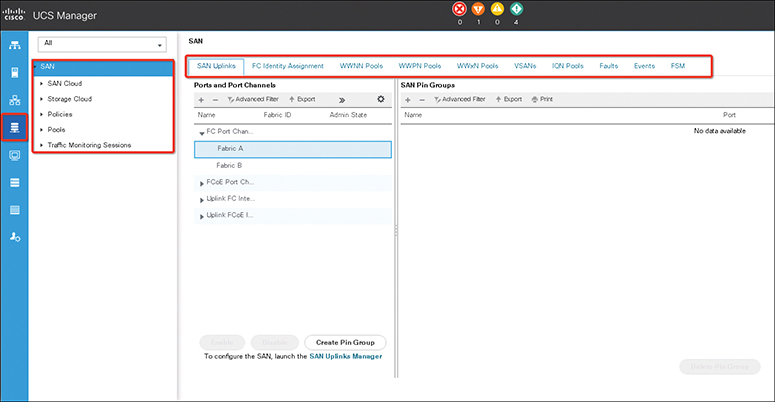
Figure 11-62 The Cisco UCS Manager’s SAN Tab
Virtual Storage-Area Networks
A virtual storage-area network, or VSAN, is a logical partition in a storage-area network. The VSAN isolates traffic to that external SAN, including broadcast traffic. The Cisco UCS supports a maximum of 32 VSANs. The Cisco UCS uses named VSANs, which are similar to named VLANs. The name that you assign to a VSAN ID adds a layer of abstraction that allows you to globally update all servers associated with service profiles that use the named VSAN. You do not need to reconfigure the servers individually to maintain communication with the external SAN. You can create more than one named VSAN with the same VSAN ID. Then you can use the VSAN name used in the profile. The traffic on one named VSAN knows that the traffic on another named VSAN exists but cannot read or access that traffic.
Named VSANs Configurations
In a cluster configuration, a named VSAN can be configured to be accessible only to the Fibre Channel uplink ports on one fabric interconnect or to the Fibre Channel uplink ports on both fabric interconnects. You must configure each named VSAN with an FCoE VLAN ID. This property determines which VLAN is used for transporting the VSAN and its Fibre Channel packets.
The following steps show how to create a named VSAN and storage VSAN:
Step 1. In the Navigation pane, click SAN. Then expand SAN > SAN Cloud.
Step 2. In the Work pane, click the VSANs tab. On the icon bar to the right of the table, click + (the plus sign). If the + icon is disabled, click an entry in the table to enable it.
Step 3. In the Create VSAN dialog box, complete the required fields, as shown in Figure 11-63. Then click OK.
Note
FCoE VLANs in the SAN cloud and VLANs in the LAN cloud must have different IDs. Using the same ID for FCoE VLANs in a VSAN and a VLAN results in a critical fault and traffic disruption for all vNICs and uplink ports using that FCoE VLAN. Ethernet traffic is dropped on any VLAN with an ID that overlaps with an FCoE VLAN ID.

Figure 11-63 Creating VSANs
The Cisco UCS Manager GUI adds the VSAN to one of the following VSANs nodes:
• The SAN Cloud > VSANs node for a storage VSAN accessible to both fabric interconnects
• The SAN Cloud > Fabric_Name > VSANs node for a VSAN accessible to only one fabric interconnect, as shown in Figure 11-64

Figure 11-64 VSAN Nodes
Step 4. In the Navigation pane, click SAN. On the SAN tab, expand SAN > Storage Cloud.
Step 5. In the Work pane, click the VSANs tab. On the icon bar to the right of the table, click +. If the + icon is disabled, click an entry in the table to enable it.
Step 6. In the Create VSAN dialog box, complete the required fields, as shown in Figure 11-65. Then click OK.

Figure 11-65 Creating Storage VSANs
The Cisco UCS Manager GUI adds the VSAN to one of the following VSANs nodes:
• The Storage Cloud > VSANs node for a storage VSAN accessible to both fabric interconnects
• The Storage Cloud > Fabric_Name > VSANs node for a VSAN accessible to only one fabric interconnect, as in Figure 11-66

Figure 11-66 VSAN Storage Nodes
Zones and Zone Sets
A zone is a collection of ports that can communicate between them over the SAN. Zoning allows you to partition the Fibre Channel fabric into one or more zones. Each zone defines the set of Fibre Channel initiators and Fibre Channel targets that can communicate with each other in a VSAN. Zoning also enables you to set up access control between hosts and storage devices or user groups. A zone has the following characteristics:
• Members in a zone can access each other; members in different zones cannot access each other.
• Zones can vary in size.
• Devices can belong to more than one zone.
• A physical fabric can have a maximum of 8000 zones.
A zone set consists of one or more zones. Zone sets provide you with flexibility to activate or deactivate all zone members in a single activity. Any changes to a zone set are not applied until the zone set is activated. A zone can be a member of more than one zone set, but only one zone set can be activated at any time. You can use zone sets to enforce access control within the Fibre Channel fabric.
The Cisco UCS Manager supports switch-based Fibre Channel zoning and Cisco UCS Manager-based Fibre Channel zoning. You cannot configure a combination of zoning types in the same Cisco UCS domain. However, you can configure a Cisco UCS domain with one of the following types of zoning:
• Cisco UCS Manager-based Fibre Channel zoning: This configuration combines direct-attached storage with local zoning. Fibre Channel or FCoE storage is directly connected to the fabric interconnects, and zoning is performed in the Cisco UCS Manager using Cisco UCS local zoning. Any existing Fibre Channel or FCoE uplink connections need to be disabled. The Cisco UCS does not currently support active Fibre Channel or FCoE uplink connections coexisting with the utilization of the UCS Local Zoning feature.
• Switch-based Fibre Channel zoning: This configuration combines direct-attached storage with uplink zoning. The Fibre Channel or FCoE storage is directly connected to the fabric interconnects, and zoning is performed externally to the Cisco UCS domain through an MDS or Nexus 5000 switch. This configuration does not support local zoning in the Cisco UCS domain.
Note
Zoning is configured on a per-VSAN basis. You cannot enable zoning at the fabric level.
The following steps show how to create a new Fibre Channel zone profile:
Step 1. In the Navigation pane, click SAN.
Step 2. On the SAN tab, click Storage Cloud.
Step 3. Right-click FC Zone Profiles and choose Create FC Zone Profile, as shown in Figure 11-67.
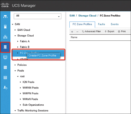
Figure 11-67 Creating an FC Zone Profile
Step 4. In the Create FC Zone Profile dialog box, complete the following fields (see Figure 11-68).

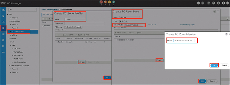
Figure 11-68 Adding an FC Zone Member
Step 5. Complete the following fields in the Create FC User Zone dialog box.

Step 6. Click OK to close the Create FC Zone Member window. Then click OK again to close the Create FC User Zone window. Then click OK to close the Create FC Zone Profile window. The new Fibre Channel zone profile is created and listed under FC Zone Profiles, as shown in Figure 11-69.
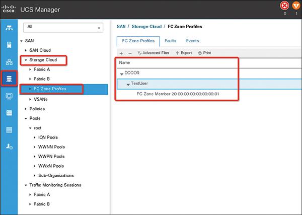
Figure 11-69 Zone Profile List
World Wide Name Pool
A World Wide Name pool is a collection of WWNs for use by the Fibre Channel vHBAs in a Cisco UCS domain. If you use WWN pools in service profiles, you do not have to manually configure the WWNs that will be used by the server associated with the service profile. In a system that implements multitenancy, you can use a WWN pool to control the WWNs used by each organization.
• A WWNN pool is a WWN pool that contains only World Wide Node Names. If you include a pool of WWNNs in a service profile, the associated server is assigned a WWNN from that pool.
• A WWPN pool is one that contains only World Wide Port Names. If you include a pool of WWPNs in a service profile, the port on each vHBA of the associated server is assigned a WWPN from that pool.
• A WWxN pool is a WWN pool that contains both World Wide Node Names and World Wide Port Names. You can specify how many ports per node are created with WWxN pools. The pool size must be a multiple of ports-per-node + 1. For example, if you specify 7 ports per node, the pool size must be a multiple of 8. If you specify 63 ports per node, the pool size must be a multiple of 64.
You can use a WWxN pool whenever you select a WWNN or WWPN pool. The WWxN pool must be created before it can be assigned.
You create separate pools for the following:
• World Wide Node Names assigned to the vHBA
• World Wide Port Names assigned to the vHBA
• Both World Wide Node Names and World Wide Port Names
The following steps show how to create WWxN pool:
Step 1. In the Navigation pane, click SAN. Then in the SAN tab, expand SAN > Pools.
Step 2. Expand the node for the organization where you want to create the pool. If the system does not include multitenancy, expand the root node, right-click WWxN Pools, and select Create WWxN Pool.
Step 3. In the Define Name and Description page of the Create WWxN Pool wizard, complete the following fields (see Figure 11-70).

Step 4. Click Next.
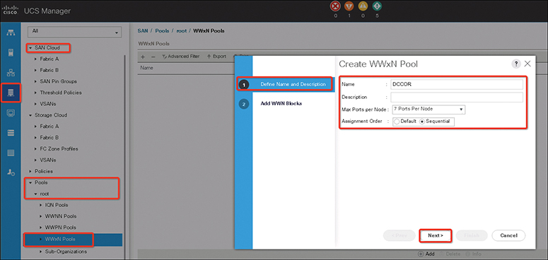
Figure 11-70 Creating WWxN Pool
Step 5. In the Add WWN Blocks page of the Create WWxN Pool wizard, click Add. In the Create WWN Block dialog box, complete the following fields (see Figure 11-71).

Step 6. Click OK and then click Finish.
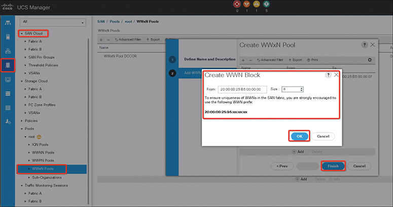
Figure 11-71 Adding a WWxN Block
Note
A WWN pool can include only WWNNs or WWPNs in the ranges from 20:00:00:00:00:00:00:00 to 20:FF:00:FF:FF:FF:FF:FF or from 50:00:00:00:00:00:00:00 to 5F:FF:00:FF:FF:FF:FF:FF. All other WWN ranges are reserved. When Fibre Channel traffic is sent through the Cisco UCS infrastructure, the source WWPN is converted to a MAC address. You cannot use WWPN pool that can translate to a source multicast MAC address. To ensure the uniqueness of the Cisco UCS WWNNs and WWPNs in the SAN fabric, Cisco recommends using the following WWN prefix for all blocks in a pool: 20:00:00:25:B5:XX:XX:XX.
SAN Connectivity Policies
SAN connectivity policies determine the connections and the network communication resources between the server and the SAN. These policies use pools to assign WWNs and WWPNs to servers and to identify the vHBAs that the servers use to communicate with the network. You can configure SAN connectivity for a service profile through either of the following methods:
• Local vHBAs that are created in the service profile
• Local SAN connectivity policy
• Local vHBAs connectivity policy
The Cisco UCS maintains mutual exclusivity between connectivity policies and local vHBA configuration in the service profile. You cannot have a combination of connectivity policies and locally created vHBAs. When you include a SAN connectivity policy, all existing vHBA configuration in that service profile is erased.
The following steps show how to create a SAN connectivity policy:
Step 1. In the Navigation pane, click SAN. Then expand SAN > Policies. Expand the node for the organization where you want to create the policy. If the system does not include multitenancy, expand the root node. Right-click SAN Connectivity Policies and choose Create SAN Connectivity Policy.
Step 2. In the Create SAN Connectivity Policy dialog box, enter a name and optional description. From the WWNN Assignment drop-down list in the World Wide Node Name area, do one of the following:
• Choose Select (pool default used by default) to use the default WWN pool.
• Choose one of the options listed under Manual Using OUI and then enter the WWN in the World Wide Node Name field. You can specify a WWNN in the range from 20:00:00:00:00:00:00:00 to 20:FF:FF:FF:FF:FF:FF:FF or from 50:00:00:00:00:00:00:00 to 5F:FF:FF:FF:FF:FF:FF:FF. You can click the here link to verify that the WWNN you specified is available.
• Choose a WWN pool name from the list to have a WWN assigned from the specified pool. Each pool name is followed by two numbers in parentheses that show the number of WWNs still available in the pool and the total number of WWNs in the pool.
Step 3. In the vHBAs table, click Add. In the Create vHBAs dialog box, enter the name and an optional description. Then choose the Fabric ID, Select VSAN, Pin Group, Persistent Binding, and Max Data Field Size. You can also create a VSAN or SAN pin group from this area.
Step 4. In the Operational Parameters area, choose the Stats Threshold Policy. In the Adapter Performance Profile area, choose the Adapter Policy and QoS Policy. You can also create a Fibre Channel adapter policy or QoS policy from this area.
Step 5. After you have created all the vHBAs you need for the policy, click OK.
Exam Preparation Tasks
As mentioned in the section “How to Use This Book” in the Introduction, you have a couple of choices for exam preparation: the exercises here, Chapter 20, “Final Preparation,” and the exam simulation questions in the Pearson Test Prep software online.
Review All Key Topics
Review the most important topics in the chapter, noted with the key topic icon in the outer margin of the page. Table 11-6 lists a reference to these key topics and the page numbers on which each is found.
![]()
Table 11-6 Key Topics for Chapter 11

Define Key Terms
Define the following key terms from this chapter, and check your answers in the Glossary.
Internet of Things (IoT)
virtual storage-area network (VSAN)
Small Computer System over IP (iSCSI)
Fiber Channel (FC)
Fiber Channel over Ethernet (FCoE)
World Wide Port Name (WWPN)
World Wide Node Name (WWNN)
just a bunch of disks (JBOD)
Small Form-Factor Pluggable Plus (SFP+)
Quad Small Form-Factor Pluggable (QSFP)
virtual interface card (VIC)
host bus adapter (HBA)
Kernel-based Virtual Machine (KVM)
Zoning
References
Cisco UCS Manager Network Management Guide, Release 4.0: https://www.cisco.com/c/en/us/td/docs/unified_computing/ucs/ucs-manager/GUI-User-Guides/Network-Mgmt/4-0/b_UCSM_Network_Mgmt_Guide_4_0.html
Cisco UCS Manager Storage Management Guide, Release 4.0: https://www.cisco.com/c/en/us/td/docs/unified_computing/ucs/ucs-manager/GUI-User-Guides/Storage-Mgmt/4-0/b_UCSM_GUI_Storage_Management_Guide_4_0.html
Cisco UCS Manager Server Management Guide, Release 4.0 Updated: https://www.cisco.com/c/en/us/td/docs/unified_computing/ucs/ucs-manager/GUI-User-Guides/Server-Mgmt/4-0/b_Cisco_UCS_Manager_Server_Mgmt_Guide_4_0.html
Cisco UCS B260 M4 and B460 M4 Blade Server Installation and Service Note for Servers with E7 v4 CPUs: https://www.cisco.com/c/en/us/td/docs/unified_computing/ucs/hw/blade-servers/install/b_B260_M4_E7v4.html
Cisco UCS C240 M5 Server Installation and Service Guide: https://www.cisco.com/c/en/us/td/docs/unified_computing/ucs/c/hw/C240M5/install/C240M5.html
Cisco Live UCS Fundamentals BRKCOM 1001: https://www.ciscolive.com/c/dam/r/ciscolive/apjc/docs/2016/pdf/BRKCOM-1001.pdf
Cisco Live UCS Networking Deep Dive BRKCOM-2003: https://www.alcatron.net/Cisco%20Live%202015%20Melbourne/Cisco%20Live%20Content/Data%20Centre/BRKCOM-2003%20UCS%20Networking%20Deep%20Dive.pdf