
Chapter 16. Evaluate Automation and Orchestration Technologies
Most of the early automation tools were developed for server automation. As use cases of automation increased, many companies developed products that supported automation from day one. Cisco is no different; it developed several products such as the Cisco UCS Server, Cisco Nexus switches, and Cisco ACI, which now support automation tools such as Ansible and Puppet. Automation tools help maintain consistent configuration throughout a network with no or minimal human intervention. Some automation tools are agentless, such as Ansible, which utilizes device-specific APIs or SSH to push configuration to network devices, and do not require installation of an agent. However, some automation tools, such as Puppet, work with the help of an agent, meaning they are installed on the network devices, which are responsible for converting configuration details to a device-specific configuration.
This chapter discusses the following key topics:
• Ansible: This section discusses Ansible concepts, components, and Ansible command-line interface (CLI) tools. Later in this section, we look at a Cisco NX-OS Ansible example.
• Puppet: This section discusses Puppet workflow, integration with the NX-OS environment, Puppet master and agent installation, resource types, along with Puppet and Cisco UCS Manager integration.
• Python: This section discusses the Python package for Cisco, CLI command APIs, Python in interactive and noninteractive mode, UCS Manager Python SDK, and the Convert to UCS Python API.
• PowerOn Auto Provisioning (POAP): This section discusses limitations and network requirements for POAP, POAP configuration scripts, POAP processes, and how to configure a switch using POAP.
• DCNM: This section discusses the Data Center Network Manager (DCNM) features and benefits, along with the Cisco DCNM Web User Interface.
• Cisco UCS Director: This section discusses automation and orchestration features and benefits of the Cisco UCS Director and Cisco UCS Director system setup.
• PowerShell: This section discusses the installation process of the Cisco UCS Director PowerShell agent. Later in this section, we discuss how to execute PowerShell agent commands.
”Do I Know This Already?” Quiz
The “Do I Know This Already?” quiz enables you to assess whether you should read this entire chapter thoroughly or jump to the “Exam Preparation Tasks” section. If you are in doubt about your answers to these questions or your own assessment of your knowledge of the topics, read the entire chapter. Table 16-1 lists the major headings in this chapter and their corresponding “Do I Know This Already?” quiz questions. You can find the answers in Appendix A, “Answers to the ‘Do I Know This Already?’ Quizzes.”
Table 16-1 “Do I Know This Already?” Section-to-Question Mapping”

Caution
The goal of self-assessment is to gauge your mastery of the topics in this chapter. If you do not know the answer to a question or are only partially sure of the answer, you should mark that question as wrong for purposes of the self-assessment. Giving yourself credit for an answer you correctly guess skews your self-assessment results and might provide you with a false sense of security.
1. Which structured format are Ansible playbooks written in?
a. JSON
b. XML
c. YAML
d. TOML
2. Which statements are CORRECT for the Ansible automation tool? (Choose two answers.)
a. Engineers create Ansible playbooks in JSON that describe a workflow or the configuration of the infrastructure.
b. Ansible scripts run on Cisco devices using Ansile Agent installed on the remote hosts.
c. When the control station runs the Ansible playbooks, they typically copy modules written in Python to remote hosts.
d. Ansible runs the modules on the remote hosts to perform the work described in playbooks.
3. Which platform does not support Puppet agent installation?
a. Bash shell
b. Guest shell
c. Open Agent Container (OAC)
d. NX-OS command line
4. Which command starts the Puppet agent process?
a. yum install $PUPPET_RPM
b. yum install puppet
c. gem install cisco_node_utils
d. puppet agent -t
5. What is the name of the Python package for Cisco?
a. cisco
b. cisco_secret
c. cisco_socket
d. cisco.acl
6. When it is used for executing CLI commands, which API prints the command output directly to stdout and returns nothing to Python?
a. cli()
b. clid()
c. clip()
d. clistdout()
7. Which of the following statements about POAP are INCORRECT? (Choose two answers.)
a. For the POAP feature to function, the switch software image must support POAP.
b. Checking for a USB device containing the configuration script file in POAP mode is supported on the Cisco Nexus 9000 Series switches.
c. The POAP process requires a minimum DHCP lease period of 1800 seconds (30 minutes).
d. POAP does not support provisioning of the switch after it has been configured and is operational.
8. Which of the following is NOT a phase of POAP process?
a. DHCP discovery phase
b. Configuration loading phase
c. Script execution phase
d. Post-installation reload phase
9. The Data Center Network Manager (DCNM) can be deployed in which of the following variants? (Choose three answers.)
a. Classic LAN
b. LAN Fabric
c. Data center LAN
d. SAN management
10. Which of the following is not a menu item in DCNM Classic LAN deployment?
a. Topology
b. Control
c. Configure
d. Applications
11. Which of the following statements is INCORRECT regarding workflows in the UCS Director?
a. A workflow is an organized set of tasks that can be executed to automate simple or complex IT processes.
b. Once built and validated, the workflow performs the same way every time, no matter who runs the workflow.
c. The workflow works only on supported Cisco hardware and doesn’t support non-Cisco hardware.
d. When you are constructing workflows by dragging and dropping tasks, it is possible to route the output of one workflow into the input of another workflow.
12. Which of the following provides visibility into the infrastructure resources utilization, critical performance metrics across the IT infrastructure stack, and capacity in real time?
a. CloudSense Analytics
b. Catalogs
c. Multidomain Manager
d. Network Element
13. Which of the following statements is INCORRECT regarding the UCS Director PowerShell agent?
a. The PowerShell agent executes cmdlets and scripts on the target server in a PowerShell remote session.
b. Windows Remote Management (WinRM) must be enabled on a Windows machine where PowerShell agent is installed to accept remote PowerShell commands.
c. The Cisco UCS Director sends the HTTP-encoded command to the PowerShell agent.
d. The PowerShell agent returns the output to the Cisco UCS Director as the payload in an HTTPS response.
Foundation Topics
Ansible
Ansible is an agentless configuration management or orchestration tool. Users have the flexibility to turn their laptops into an Ansible control station to automate basic tasks, or they can deploy a dedicated host to use Ansible as an orchestration tool to roll out application updates while ensuring minimal downtime. Ansible provides a simple domain-specific language (DSL) to enable these different use cases. Ansible is popular among infrastructure engineers and developers because it requires minimal time and effort to get up and running. Before describing the specifics of Ansible, the following sections provide a high-level overview of how Ansible works.
A basic workflow for Ansible using playbooks looks something like that shown in Figure 16-1:
1. Engineers create Ansible playbooks in YAML that describe a workflow or the configuration of infrastructure.
2. Ansible playbooks are deployed to an Ansible control station.
3. When the control station runs the Ansible playbooks, they typically copy modules written in Python to remote hosts.
4. Finally, Ansible runs the modules on the remote hosts to perform the work described in playbooks.
![]()
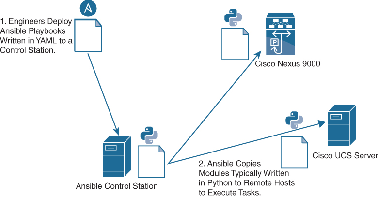
Figure 16-1 Workflow for Ansible Using Playbooks
Ansible Components
Ansible requires a control machine to run the Ansible tool. By default, Ansible uses a push model to push changes to remote hosts from the Ansible control machine. The control machine can be any Linux/UNIX host with a Python interpreter that supports SSH or the required transport to devices managed by Ansible. Some of the important components of the Ansible control machine are as follows:
![]()
• Modules are typically written in Python. They are typically copied to remote hosts and run by the Ansible tool. Ansible modules are referenced as tasks in Ansible playbooks or using CLI arguments in the Ansible ad hoc CLI tool.
• Inventory files contain the hosts operated by Ansible. They contain group and host definitions that can be referenced by Ansible playbooks or using CLI arguments from the Ansible ad hoc CLI tool. A host can belong to multiple groups.
• Playbooks are written in YAML and contain Ansible domain-specific language. To enable reuse, playbooks can be modularized much like software. Variables containing data for playbooks can be separated into YAML files residing on the Ansible control machine.
• Configuration files control how the tool runs. For example, the configuration file can change the default directories of the modules.
Important Ansible Concepts
Following are the important Ansible components:
• Authentication: Ansible uses SSH primarily for transport. Given that, you must have a way to handle authentication. By default, Ansible assumes engineers use public key infrastructure (SSH keys) instead of usernames and passwords for authentication. This enables engineers to access hosts without typing out passwords every time playbooks are run. If needed, this default behavior can be overridden.
• Ansible play: An Ansible play is a component of the Ansible DSL created within Ansible playbooks. A play is a mapping of hosts to tasks in a playbook. Hosts are typically identified by groups that are defined in inventory files. Tasks are lists of the Ansible modules that are run against groups of hosts.
• Variables: Ansible playbooks use double curly braces {{ }} to enclose variables. This enables the Ansible tool to perform variable substitution. Let’s look at an example: different data centers use different ports for a services such as web applications. Every data center has different configuration parameters for AD/DNS servers, NTP servers, and so on. When automating tasks using Ansible, you provide these unique combinations to playbooks using variables. There are two ways to provide variables to the Ansible tool:
• CLI prompt: The Ansible DSL contains an option, vars_prompt:, that enables the operator to provide variable data using a CLI. This is primarily useful when running simple playbooks manually to automate tasks.
• Variable files: Variables can also be defined in YAML files and referenced in playbooks. There are different types of variable files. Some variables have global scope using the vars_files: Ansible DSL. Other variables, called group variables, can be applied to specific groups defined in the inventory file. Others, called host variables, are applied to specific hosts in the inventory.
• Jinja templates: Ansible can use jinja2 template functionality to autogenerate configuration for network devices. While doing so, templates replace the variables defined with appropriate values.
• Roles: One common approach is to organize playbooks using roles, which enable reuse. To enable reuse, roles provide a structure for variables, playbooks, templates, and other required files.
Ansible CLI Tools
Ansible provides CLI tools that enable automation. The most useful CLI tools that Ansible provides include the following:
• The ansible CLI tool runs modules against targeted hosts. This is commonly referred to as the ad hoc CLI. Engineers can run tasks against targeted hosts without creating playbooks containing Ansible DSL.
• The ansible-playbook CLI tool runs playbooks against targeted hosts. Playbooks contain Ansible domain-specific language in YAML.
• The ansible-vault CLI tool enables engineers to encrypt sensitive data. If a playbook requires access to data that engineers do not want to expose in plain text, the ansible-vault tool can be used to create an encrypted YAML file containing the sensitive data. When data needs to be accessed, a password is provided.
• The ansible-pull tool enables clients to “pull” modules from a centralized server. (Normally, Ansible pushes modules out from a control station to the managed hosts.)
• The ansible-docs CLI tool enables engineers to parse the docstrings of Ansible modules to see sample syntax and the parameters that modules require.
• The ansible-galaxy tool can create or download roles from the Ansible community. Ansible Galaxy is a public repository of Ansible playbooks grouped into roles from the community. Roles provide a method to package Ansible playbooks for reuse.
Cisco NX-OS and Ansible Example
All the Cisco NX-OS modules are included in Ansible Core as of Ansible 2.2, so no additional effort is required to begin automating your Nexus devices. Because Ansible has an agentless architecture, when the NXAPI feature is enabled, and a username and password are configured, the devices can be managed through Ansible. The username provided in the playbook must have the requisite role privilege to allow device configuration changes.
Example 16-1 shows an Ansible playbook that is written using the YAML format, ensuring that VLANs 2, 15, and 20 are created with proper names.
Example 16-1 Ansible Playbook Example
---
- name: vlan provisioning
  hosts: n9kv-1
  connection: local
  gather_facts: no

vars:
 nxos_provider:
  username: “{{ un }}”
  password: “{{ pwd }}”
  transport: nxapi
  host: “{{ inventory_hostname }}”

tasks:

 - name: CREATE VLANS AND ASSIGN A NAME, USING VLAN_ID
   nxos_vlan:
    vlan_id: “{{ item.vlan_id }}”
    name: “{{ item.name }} “
    provider: “{{ nxos_provider }}”
   with_items:
    - vlan_id: 2
      name: native
    - vlan_id: 15
      name: web
    - vlan_id: 20
      name: app
The playbook has these fields:
• The name: field defines the playbook name.
• The hosts:n9kv-1 field specifies the set of hosts that will be configured by the playbook.
• The connection:local field denotes that the task will be handled by Ansible, just like a local action.
• The gather_facts: no field denotes that no information from the device will be collected.
• The tasks: field specifies the task that will be run on the Nexus device.
• The vars: field defines the username and password and transport method to achieve the tasks at hand. In this example, the configuration will be done using NXAPI as the transport method.
Ansible is idempotent, in that it will only make a change on the devices if a change is necessary. If the configuration is already present, no changes will be made.
Note
For Cisco UCS Servers, the UCS Manager Software Development Kit (UCSMSDK) is required to be present on the host against which the playbook is executed. Ansible 2.5 and later versions support Cisco UCS modules. The Ansible module uses the UCS API to execute automation tasks on Cisco UCS Servers.
Puppet
The Puppet software package, developed by Puppet Labs, is an open-source automation toolset for managing servers and other resources. The Puppet software accomplishes server and resource management by enforcing device states, such as configuration settings.
Puppet components include a Puppet agent, which runs on the managed device (node), and a Puppet master (server). The Puppet master typically runs on a separate dedicated server and serves multiple devices. The operation of the Puppet agent involves periodically connecting to the Puppet master, which in turn compiles and sends a configuration manifest to the agent. The agent reconciles this manifest with the current state of the node and updates state that is based on differences.
A puppet manifest is a collection of property definitions for setting the state on the device. The details for checking and setting these property states are abstracted so that a manifest can be used for more than one operating system or platform. Manifests are commonly used for defining configuration settings, but they also can be used to install software packages, copy files, and start services.
Figure 16-2 illustrates how Puppet automation can be integrated with Cisco Nexus and UCS devices.
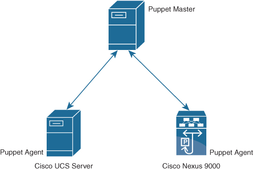
Figure 16-2 Puppet Overview
Puppet Workflow
![]()
The process of getting network devices to a desired configuration state using Puppet automation is as follows (see Figure 16-3):
1. Define: With Puppet’s declarative language, you design a graph of a relationship between resources within reusable modules called manifests. The manifests define your infrastructure in its desired state.
2. Simulate: Using manifests, Puppet simulates deployments, enabling you to test changes without disruption to your infrastructure.
3. Enforce: Puppet compares your system to the desired state as you define it, and automatically enforces it to the desired state, ensuring your system is in compliance.
4. Report: The Puppet Dashboard reports back the relationship between components and all changes. And with the open API, you can integrate Puppet with third-party monitoring tools.
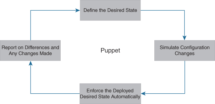
Figure 16-3 Puppet Workflow
Puppet and NX-OS Environment Integration
The ciscopuppet module allows a network administrator to manage Cisco Nexus network elements using Puppet. The Puppet agent is supported on Cisco Nexus 3000, 5000, 6000, 7000, and 9000 Series of switches. The Puppet agent can be installed on various NX-OS environments as shown in Table 16-2.
Table 16-2 Supported Cisco Nexus Platforms for Puppet Agent Installation

Note
Starting in NX-OS release 9.2(1) and onward, installing a Puppet agent in the Bash-shell hosting environment is no longer supported. Instead, the Puppet agent software should be installed on the Guest shell hosting environment.
Figure 16-4 shows the steps involved in Manual Puppet installation on Cisco Nexus switches.
![]()
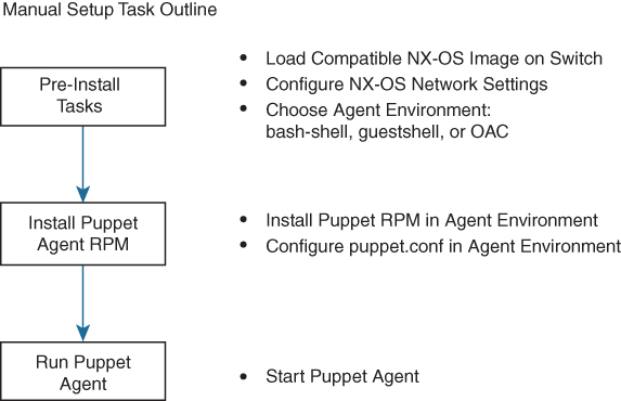
Figure 16-4 Manual Puppet Installation Steps on Cisco Nexus Switches
You need to ensure that IP reachability exists between the agent node and the Puppet server. You then configure NTP to ensure that the agent node time is in sync with the Puppet server.
Puppet Master Installation
For managing Cisco devices using Puppet agents, the Puppet master needs to install the ciscopuppet module. You can use the following command to install the ciscopuppet module on the Puppet master:
puppet module install puppetlabs-ciscopuppet
Puppet Agent Installation
This section is common to Bash shell, Guest shell, and the Open Agent Container. The following steps guide you through the installation process of the Puppet agent on Cisco NX-OS software:
Step 1. Select and install the Puppet agent RPM. Here, you import the Puppet GPG keys and install the appropriate Puppet RPM for your agent environment.
Install GPG Keys:
rpm --import http://yum.puppetlabs.com/RPM-GPG-KEY-puppetlabs
rpm --import http://yum.puppetlabs.com/RPM-GPG-KEY-reductive
rpm --import http://yum.puppetlabs.com/RPM-GPG-KEY-puppet
Table 16-3 shows RPM URLs for the different environments on NX-OS.
Table 16-3 RPM URLs For Different Environments on NX-OS

Install RPM using the following command:
yum install $PUPPET_RPM
yum install puppet
where $PUPPET_RPM is the URL from Table 16-3.
Update the path variable using the following command:
export PATH=/opt/puppetlabs/puppet/bin:/opt/puppetlabs/puppet/lib:$PATH
Step 2. Add the Puppet server name to the configuration file at /etc/puppetlabs/puppet/puppet.conf:
[main]
  server   = mypuppetmaster.mycompany.com
  certname = this_node.mycompany.com
where this_node is the host name of the Nexus device and mycompany.com is the domain name configured under VRF management.
Step 3. Install the cisco_node_utils gem.
The cisco_node_utils Rubygem is a required component of the ciscopuppet module. This gem contains platform APIs for interfacing between Cisco CLI and Puppet agent resources. The Puppet agent can automatically install the gem by simply using the ciscopuppet::install helper class, or it can be installed manually. The following command installs cisco_node_utils manually:
gem install cisco_node_utils
Step 4. Run the Puppet agent.
Executing the puppet agent command (with no arguments) will start the Puppet agent process with the default run interval of 30 minutes. Use the -t option to run the Puppet agent in test mode, which runs the agent a single time and stops:
puppet agent -t
The Cisco Nexus network elements and operating systems managed by this Puppet module are continuously expanding. This GitHub repository contains the latest version of the ciscopuppet module source code. Supported versions of the ciscopuppet module are available at Puppet Forge.
Resource Types
Puppet has predefined resource types that can be used to configure features on NX-OS. Some of the resource types are shown in Table 16-4.
![]()
Table 16-4 Puppet Resource Types

Sample Manifest: OSPF
The following example demonstrates how to define a manifest that uses ciscopuppet to configure OSPF on a Cisco Nexus switch. Three resource types are used to define an OSPF instance, basic OSPF router settings, and OSPF interface settings:
• cisco_ospf
• cisco_ospf_vrf
• cisco_interface_ospf
The first manifest type defines the router instance using cisco_ospf. The title ‘Sample’ becomes the router instance name:
cisco_ospf {“Sample”:
   ensure => present,
}
The next type to define is cisco_ospf_vrf. The title includes the OSPF router instance name and the VRF name. Note that a non-VRF configuration uses ‘default’ as the VRF name:
cisco_ospf_vrf {“Sample default”:
   ensure => ‘present’,
   default_metric => ‘5’,
   auto_cost => ‘46000’,
}
Finally, you define the OSPF interface settings. The title here includes the interface name and the OSPF router instance name:
cisco_interface_ospf {“Ethernet1/5 Sample”:
   ensure => present,
   area => 100,
   cost => “100”,
}
Puppet and Cisco UCS Manager Integration
The Cisco Puppet module for UCSM allows administrators to automate all aspects of Cisco UCS management, including server, network, storage, and hypervisor management. The bulk of the Cisco UCSM Puppet module works on the UCS Manager’s Management Information Tree (MIT), performing create, modify, or delete actions on the managed objects (MOs) in the tree. The ucsm module has a dependency on the ucsmsdk Python library.
Example 16-2 shows a Puppet manifest that uses the ucsm module to configure the VLAN on a Cisco UCS.
Example 16-2 Puppet Manifest Example
ucsm_vlan{‘fabricVlan’:
policy_name => “vlan603”,
id => “603”,
default_net => “yes”,
ip => “192.168.10.132”,
username => “admin”,
password => “password”,
state => “present”,
}
Example 16-2 has the following fields:
• ucsm_vlan: The VLAN resource type defined in the Puppet DSL. This is required to identify which resource you intend to configure.
• policy_name: This is the name of the policy to be configured.
• default_net: If the newly created VLAN is a native VLAN, this parameter has to be set to “yes”. Otherwise, it should be set to “no”.
• id: This is the range of VLAN IDs (for example, “2009-2019”, “29,35,40-45”, “23”, “23,34-45”).
• ip: This is the IP address of the UCS server.
• username: This is the administrative username.
• password: This is the administrative password.
• state: This parameter ensures whether the policy should be present or absent on the UCS server.
Python
Python is a programming language that has high-level data structures and a simple approach to object-oriented programming. Python’s syntax and dynamic typing, together with its interpreted nature, make it an ideal language for scripting and rapid application development in many areas on most platforms.
The Python interpreter and the standard library are freely available in source or binary form for all major platforms from the Python website at www.python.org. The Python website also distributes and links to many free third-party Python modules, programs and tools, and additional documentation.
The Cisco Nexus Series devices support Python version 2.7.5 in both interactive and noninteractive (script) modes. Python is also supported in the Guest Shell.
The Python scripting capability provides programmatic access to the device’s CLI to perform various tasks and PowerOn Auto Provisioning (POAP) or Embedded Event Manager (EEM) actions. Python can also be accessed from the Bash shell.
The Python scripting capability on Cisco Nexus switches enables you to perform the following tasks:
• Run a script to verify configuration on switch bootup.
• Back up a configuration.
• Perform proactive congestion management by monitoring and responding to buffer utilization characteristics.
• Perform integration with the PowerOn Auto Provisioning or EEM modules.
• Perform a job at a specific time interval (such as Port Auto Description).
• Programmatically access the switch command-line interface to perform various tasks.
Python Package for Cisco
Cisco NX-OS provides a Python package named cisco package that enables access to many core network device modules, such as interfaces, VLANs, VRFs, ACLs, and routes. After you have imported the cisco package, you can display its help by entering help (cisco) at the Python prompt. To display help on a specific module in the Cisco Python package, enter help(cisco.module_name), where module_name is the name of the module. For example, to display help on the Cisco ACL module, enter help (cisco.acl).
Example 16-3 shows how to display information about the Python package for Cisco.
Example 16-3 Python Package for Cisco
>>> import cisco
>>> help(cisco)
Help on package cisco:

NAME
    cisco

FILE
    /isan/python/scripts/cisco/__init__.py

PACKAGE CONTENTS
    acl
    bgp
    cisco_secret
    cisco_socket
    feature
    interface
    key
    line_parser
    md5sum
    nxcli
    ospf
    routemap
    routes
    section_parser
    ssh
    system
    tacacs
    vrf

CLASSES
     __builtin__.object
        cisco.cisco_secret.CiscoSecret
        cisco.interface.Interface
        cisco.key.Key
The methods and functions in the Python package named cisco are implemented in Python source files included with the software development kit (SDK) package. Many of these files have documentation embedded within the source code. In the Python source files, documentation is contained in documentation strings, bracketed by three backticks, or ```. Some source files and methods are for internal use and do not have embedded documentation.
Table 16-5 shows the functionality that the cisco package provides.
Table 16-5 Cisco Package Functions

From the cisco package, you can import individual modules as needed using
from cisco.module_name import *
where module_name is the name of the individual module. In the example, the ACL module is imported.
>>> import cisco
>>> from cisco.acl import *
Other useful modules include the cli package and the json package. The cli package is used to allow Python scripts running on the NX-OS device to interact with the CLI to get and set configuration on the device. This library has one function within it named cli. The input parameters to the function are the CLI commands the user wants to run, and the output is a string representing the parser output from the CLI command.
>>> from cli import *
>>> import json
After starting Python and importing the required packages and modules, you can run Python scripts directly, or you can enter blocks of Python code and run the code.
Using the CLI Command APIs
The Python programming language uses three APIs that can execute CLI commands. The APIs are available from the Python CLI module.
![]()
You must enable the APIs with the from cli import * command. The arguments for these APIs are strings of CLI commands. To execute a CLI command through the Python interpreter, you enter the CLI command as an argument string of one of the following APIs:
1. cli() returns the raw output of CLI commands, including control or special characters. The interactive Python interpreter prints control or special characters “escaped.” A carriage return is printed as ‘ ’ and gives results that can be difficult to read. The clip() API gives results that are more readable.
Example: string = cli (“cli-command”)
2. clid() returns JSON output for the CLI command, if XML support exists for the command; otherwise, an exception is thrown. This API can be useful when searching the output of show commands.
Example: json_string = clid (“cli-command”)
3. clip() prints the output of the CLI command directly to stdout and returns nothing to Python.
Example: clip (“cli-command”)
When two or more commands are run individually, the state is not persistent from one command to subsequent commands.
In the following example, the second command fails because the state from the first command does not persist for the second command:
>>> cli(“conf t”)
>>> cli(“interface eth4/1”)
When two or more commands are run together, the state is persistent from one command to subsequent commands.
In the following example, the second command is successful because the state persists for the second and third commands:
>>> cli(“conf t ; interface eth4/1 ; shut”)
Note
Commands are separated with “ ; ” as shown in the example. The semicolon ( ; ) must be surrounded with single blank characters.
Python in Interactive Mode
![]()
To enter the Python shell, enter the python command from the NX-OS command line with no parameters. You can enter lines of Python code to execute a block of code. A colon (:) at the end of a line tells the Python interpreter that the subsequent lines will form a code block. After the colon, you must indent the subsequent lines in the block, following Python indentation rules. After you have typed the block, press Return or Enter twice to execute the code.
Note
The Python interpreter is designated with the >>> or … prompt.
Example 16-4 shows how to invoke Python from the CLI and run Python commands interactively.
Example 16-4 Interactive Python Example
switch# python
Python 2.7.5 (default, Feb  8 2019, 23:59:43)
[GCC 4.6.3] on linux2
Type “help”, “copyright”, “credits” or “license” for more information.
>>> from cli import *
>>> import json
>>> cli(‘configure terminal ; interface loopback 5 ; no shut’)
‘‘
>>> intflist=json.loads(clid(‘show interface brief’))
>>> i=0
>>> while i < len(intflist[‘TABLE_interface’][‘ROW_interface’]):
...   intf=intflist[‘TABLE_interface’][‘ROW_interface’][i]
...   i=i+1
...   if intf[‘state’] == ‘up’:
...     print intf[‘interface’]
...
mgmt0
Ethernet2/7
Ethernet4/7
loopback0
loopback5
>>>
The preceding example brings the loopback 5 interface UP and shows how to query the interfaces running on the switch.
To exit the Python shell, type exit():
>>>exit()
switch#
Python in Noninteractive Mode
![]()
You can run a Python script in noninteractive mode by providing the Python script name as an argument to the Python CLI command. Python scripts must be placed under the bootflash or volatile scheme. A maximum of 32 command-line arguments for the Python script are allowed with the Python CLI command.
To execute a Python script, enter the python command, followed by the filename of the script, followed by any arguments for the script, as shown in this example:
switch# python bootflash:scripts/deltaCounters.py Ethernet1/1 1 5
The Cisco Nexus switches also support the source CLI command for running Python scripts. The bootflash:scripts directory is the default script directory for the source CLI command.
switch# source deltaCounters Ethernet1/1 1 5
You can display the script source using the show file CLI command, as in Example 16-5.
Example 16-5 show file Command
switch# show file bootflash:scripts/deltaCounters.py

#!/isan/bin/python

from cli import *
import sys, time

ifName = sys.argv[1]
delay = float(sys.argv[2])
count = int(sys.argv[3])
cmd = ‘show interface ‘ + ifName + ‘ counters’

out = json.loads(clid(cmd))
rxuc = int(out[‘TABLE_rx_counters’][‘ROW_rx_counters’][0][‘eth_inucast’])
rxmc = int(out[‘TABLE_rx_counters’][‘ROW_rx_counters’][1][‘eth_inmcast’])
rxbc = int(out[‘TABLE_rx_counters’][‘ROW_rx_counters’][1][‘eth_inbcast’])
txuc = int(out[‘TABLE_tx_counters’][‘ROW_tx_counters’][0][‘eth_outucast’])
txmc = int(out[‘TABLE_tx_counters’][‘ROW_tx_counters’][1][‘eth_outmcast’])
txbc = int(out[‘TABLE_tx_counters’][‘ROW_tx_counters’][1][‘eth_outbcast’])
print ‘row rx_ucast rx_mcast rx_bcast tx_ucast tx_mcast tx_bcast’
print ‘========================================================‘
print ‘    %8d %8d %8d %8d %8d %8d’ % (rxuc, rxmc, rxbc, txuc, txmc, txbc)
print ‘=========================================================‘

i = 0
while (i < count):
  time.sleep(delay)
  out = json.loads(clid(cmd))
  rxucNew = int(out[‘TABLE_rx_counters’][‘ROW_rx_counters’][0][‘eth_inucast’])
  rxmcNew = int(out[‘TABLE_rx_counters’][‘ROW_rx_counters’][1][‘eth_inmcast’])
  rxbcNew = int(out[‘TABLE_rx_counters’][‘ROW_rx_counters’][1][‘eth_inbcast’])
  txucNew = int(out[‘TABLE_tx_counters’][‘ROW_tx_counters’][0][‘eth_outucast’])
  txmcNew = int(out[‘TABLE_tx_counters’][‘ROW_tx_counters’][1][‘eth_outmcast’])
  txbcNew = int(out[‘TABLE_tx_counters’][‘ROW_tx_counters’][1][‘eth_outbcast’])
  i += 1
  print ‘%-3d %8d %8d %8d %8d %8d %8d’ %
    (i, rxucNew - rxuc, rxmcNew - rxmc, rxbcNew - rxbc, txucNew - txuc, txmcNew - txmc, txbcNew - txbc)
The preceding output for the deltaCounters.py script shows the increment in receive and transmit counters for a specified interface over a period.
The usage is
deltaCounters.py interface seconds count
For example, deltaCounters.py Ethernet1/1 1 5 displays the counters for the Ethernet1/1 interface every 1 second for 5 periods.
Example 16-6 shows the counter values when the deltaCounters.py script is run.
Example 16-6 Counter Values When deltaCounters.py Script Is Run
switch# python bootflash:scripts/deltaCounters.py Ethernet1/1 1 5
row rx_ucast rx_mcast rx_bcast tx_ucast tx_mcast tx_bcast
=========================================================
           0      791        1        0   212739        0
=========================================================
1          0        0        0        0       26        0
2          0        0        0        0       27        0
3          0        1        0        0       54        0
4          0        1        0        0       55        0
5          0        1        0        0       81        0
switch#
The source command is helpful when executing compound commands from the CLI. Example 16-7 shows a source command following a pipe operator (|), allowing a Python script to receive input from another CLI command.
Example 16-7 Example of Compound Source Command
switch# show running-config | source sys/cgrep policy-map

policy-map type network-qos nw-pfc
policy-map type network-qos no-drop-2
policy-map type network-qos wred-policy
policy-map type network-qos pause-policy
policy-map type qos foo
policy-map type qos classify
policy-map type qos cos-based
policy-map type qos no-drop-2
policy-map type qos pfc-tor-port
In the preceding example, policy-map is an argument to the Python script named cgrep.
UCS Manager Python SDK
The Cisco UCS Python SDK is a Python module that helps automate all aspects of Cisco UCS management, including server, network, storage, and hypervisor management.
The bulk of the Cisco UCS Python SDK works on the UCS Manager’s Management Information Tree (MIT), performing create, modify, or delete actions on the managed objects (MO) in the tree.
Install Python 2.7 and above and pip before installing ucsmsdk. After Python and pip are installed, install the lastest version of the SDK from pypi using following command:
pip install ucsmsdk
You can also install the latest developer version from Github using following commands:
git clone https://github.com/CiscoUcs/ucsmsdk/
cd ucsmsdk
sudo make install
For login and logout from the UCS Manager, you need to import the UCSHandle class. The following example shows how to create a connection handle before you can log in and log out from the server.
from ucsmsdk.ucshandle import UCSHandle

# Create a connection handle
handle = UcsHandle(“192.168.1.1”, “admin”, “password”)

# Login to the server
handle.login()

# Logout from the server
handle.logout()
The SDK provides APIs to enable CRUD operations:
• Create an object: add_mo
• Retrieve an object: query_dn, query_classid, query_dns, query_classids
• Update an object: set_mo
• Delete an object: delete_mo
The preceding APIs can be bunched together in a transaction (All or None). The commit_mo operation commits the changes made using the preceding APIs. All these methods are invoked on a UCSHandle instance.
The following example creates a new service profile (LsServer) object under the parent org-root. You create managed objects by using the add_mo API:
from ucsmsdk.mometa.ls.LsServer import LsServer
sp = LsServer(parent_mo_or_dn=“org-root”, name=“sp_demo”)

handle.add_mo(sp)
The following example shows how to query an existing Mo using a distinguished name (DN) and update it:
# Query for an existing Mo
sp = handle.query_dn(“org-root/ls-sp_demo”)

# Update description of the service profile
sp.descr = “demo_descr”

# Add it to the on-going transaction
handle.set_mo(sp)
The following example shows the use of remove_mo in removing an object:
# Query for an existing Mo
sp = handle.query_dn(“org-root/ls-sp_demo”)

# Remove the object
handle.remove_mo(sp)
Note
API operations are batched together by default until a commit() is invoked.
In the following code, the objects are created only when a commit() is invoked. If there is a failure in one of the steps, no changes are committed to the server.
from ucsmsdk.mometa.ls.LsServer import LsServer
sp1 = LsServer(parent_mo_or_dn=“org-root”, name=“sp_demo1”)
handle.add_mo(sp1)

sp2 = LsServer(parent_mo_or_dn=“org-root”, name=“sp_demo2”)
handle.add_mo(sp2)

# commit the changes to server
handle.commit()
Convert to UCS Python
Wouldn’t it be cool if you didn’t have to know much about the SDK to be able to automate operations based off it?
Welcome the convert_to_ucs_python API!
The steps involved to generate a Python script equivalent to the steps performed on the UCSM GUI are as follows:
Step 1. Launch the Java-based UCSM user interface (UI).
Step 2. Launch the Python shell and invoke convert_to_ucs_python on the same machine.
Step 3. Perform the desired operation on the UI.
Step 4. The convert_to_ucs_python API monitors the operation and generates equivalent Python script for it.
The UCSM GUI logs all the activities that are performed through it, and the Python shell monitors that log to generate the equivalent Python script. Because the logging is local to the machine where the UI is running, convert_to_ucs_python also must run on the same machine.
PowerOn Auto Provisioning (POAP)
PowerOn Auto Provisioning (POAP) automates the process of upgrading software images and installing configuration files on devices that are being deployed in the network for the first time.
When a device with the POAP feature boots and does not find the startup configuration, the device enters POAP mode, locates a DHCP server, and bootstraps itself with its interface IP address, gateway, and DNS server IP addresses. The device also obtains the IP address of a TFTP server and downloads a configuration script that enables the switch to download and install the appropriate software image and configuration file.
Note
The DHCP information is used only during the POAP process.
Limitations of POAP
The switch software image must support POAP for this feature to function.
POAP does not support provisioning of the switch after it has been configured and is operational. Only autoprovisioning of a switch with no startup configuration is supported.
Network Requirements for POAP
POAP requires the following network infrastructure, as shown in Figure 16-5:
• A DHCP server to bootstrap the interface IP address, gateway address, and Domain Name System (DNS) server
• A TFTP server that contains the configuration script used to automate the software image installation and configuration process
• One or more servers that contain the desired software images and configuration files
![]()
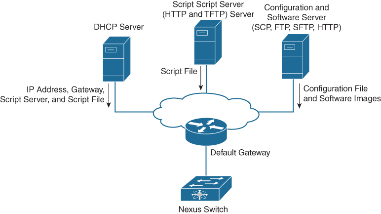
Figure 16-5 POAP Network Infrastructure
Note
Checking for a USB device containing the configuration script file in POAP mode is not supported on Cisco Nexus 9000 Series switches.
POAP Configuration Script
Cisco has sample configuration scripts that were developed using the Python programming language and Tool command language (Tcl). You can customize one of these scripts to meet the requirements of your network environment.
The reference script supplied by Cisco supports the following functionality:
• Retrieves the switch-specific identifier—for example, the serial number.
• Downloads the software image (system and kickstart images) if the files do not already exist on the switch. The software image is installed on the switch and is used at the next reboot.
• Schedules the downloaded configuration to be applied at the next switch reboot.
• Stores the configuration as the startup configuration.
For Cisco Nexus 9000 Series switches, the POAP script can be found at https://github.com/datacenter/nexus9000/blob/master/nx-os/poap/poap.py.
To modify the script using Python, see the Cisco NX-OS Python API Reference Guide for your platform.
POAP Process
The POAP process has the following phases:
1. Power up
2. USB discovery
3. DHCP discovery
4. Script execution
5. Post-installation reload
Within these phases, other process and decision points occur. Figure 16-6 shows a flow diagram of the POAP process.
![]()
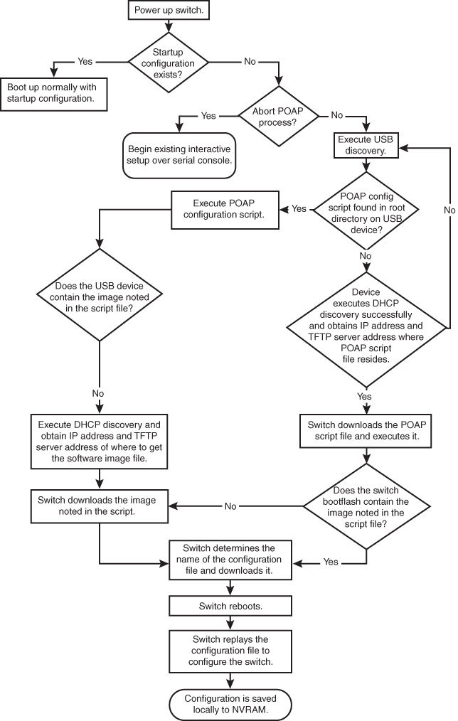
Figure 16-6 POAP Process
Power-Up Phase
When you power up the device for the first time, it loads the software image that is installed at manufacturing and tries to find a configuration file from which to boot. When a configuration file is not found, the POAP mode starts.
During startup, a prompt appears asking if you want to abort POAP and continue with a normal setup. You can choose to exit or continue with POAP.
If you exit POAP mode, you enter the normal interactive setup script. If you continue in POAP mode, all the front-panel interfaces are set up in the default configuration.
Note
No user intervention is required for POAP to continue. The prompt that asks if you want to abort POAP remains available until the POAP process is complete.
USB Discovery Phase
When POAP starts, the process searches the root directory of all accessible USB devices for the POAP configuration script file, configuration files, and system and kickstart images. If the configuration script file is found on a USB device, POAP begins running the configuration script. If the configuration script file is not found on the USB device, POAP executes DHCP discovery.
If the software image and switch configuration files specified in the configuration script are present, POAP uses those files to install the software and configure the switch. If the software image and switch configuration files are not on the USB device, POAP starts the DHCP phase from the beginning.
DHCP Discovery Phase
The switch sends out DHCP discover messages on the front-panel interfaces or the MGMT interface that solicits DHCP offers from the DHCP server or servers (see Figure 16-7). The DHCP client on the Cisco Nexus switch uses the switch serial number in the client-identifier option to identify itself to the DHCP server. The DHCP server can use this identifier to send information, such as the IP address and script filename, back to the DHCP client.
![]()
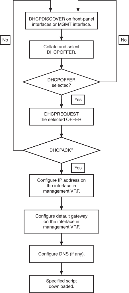
Figure 16-7 DHCP Discovery Process
POAP requires a minimum DHCP lease period of 3600 seconds (1 hour). POAP checks the DHCP lease period. If the DHCP lease period is set to less than 3600 seconds (1 hour), POAP does not complete the DHCP negotiation.
The DHCP discover message also solicits the following options from the DHCP server:
• TFTP server name or TFTP server address: The DHCP server relays the TFTP server name or TFTP server address to the DHCP client. The DHCP client uses this information to contact the TFTP server to obtain the script file.
• Bootfile name: The DHCP server relays the bootfile name to the DHCP client. The bootfile name includes the complete path to the bootfile on the TFTP server. The DHCP client uses this information to download the script file.
When multiple DHCP offers that meet the requirement are received, the one arriving first is honored, and the POAP process moves to the next stage. The device completes the DHCP negotiation (request and acknowledgment) with the selected DHCP server, and the DHCP server assigns an IP address to the switch. If a failure occurs in any of the subsequent steps in the POAP process, the IP address is released back to the DHCP server.
Figure 16-7 shows a flow diagram of the DHCP Discovery process.
Script Execution Phase
After the device bootstraps itself using the information in the DHCP acknowledgment, the script file is downloaded from the TFTP server.
The switch runs the configuration script, which downloads and installs the software image and downloads a switch-specific configuration file.
However, the configuration file is not applied to the switch at this point, because the software image that currently runs on the switch might not support all of the commands in the configuration file. After the switch reboots, it begins running the new software image, if an image was installed. At that point, the configuration is applied to the switch.
Note
If the switch loses connectivity, the script stops, and the switch reloads its original software images and bootup variables.
Post-Installation Reload Phase
The switch restarts and applies (replays) the configuration on the upgraded software image. Afterward, the switch copies the running configuration to the startup configuration.
Configuring a Switch Using POAP
Before configuring a switch using POAP, make sure that the network environment is set up to use POAP. The procedure to configure a switch using POAP is as follows:
Step 1. Install the switch in the network.
Step 2. Power on the switch.
If no configuration file is found, the switch boots in POAP mode and displays a prompt asking if you want to abort POAP and continue with a normal setup. No entry is required to continue to boot in POAP mode.
Step 3. (Optional) If you want to exit POAP mode and enter the normal interactive setup script, enter y (yes).
Step 4. The switch boots, and the POAP process begins.
Step 5. Verify the device configuration using the commands shown in Table 16-6.
Table 16-6 POAP Verification Commands

DCNM
Modern data centers are becoming increasingly complex and massive. Proliferation of new technologies such as virtualization is adding yet another level of complexity while enabling higher workloads to be placed on the network. Thus, it becomes more imperative to continuously monitor and manage the enterprise network in a comprehensive manner.
The Data Center Network Manager (DCNM) is the network management platform for all NX-OS-enabled deployments, spanning new fabric architectures, IP Fabric for Media, and storage networking deployments for the Cisco Nexus-powered data center. DCNM provides management, control, automation, monitoring, visualization, and troubleshooting across Cisco Nexus and Cisco Multilayer Distributed Switching (MDS) solutions.
Cisco DCNM has the following benefits:
• Automation: Accelerates provisioning from days to minutes and simplify deployments.
• Visibility: Reduces troubleshooting cycles with graphical operational visibility for topology, network fabric, and infrastructure.
• Consistency: Eliminates configuration errors with templated deployment models and configuration compliance alerting with automatic remediation.
![]()
DCNM can be deployed in four different variants, as illustrated in Figure 16-8:
• Classic LAN: For managing classic LAN deployments such as VLANs and vPCs.
• LAN Fabric: For fabric management for multiple types of LAN solutions, including VXLAN-EVPN, Cisco FabricPath, and traditional three-tier LAN deployments.
• Media Controller: For managing media networks.
• SAN Management: For managing SAN fabrics.
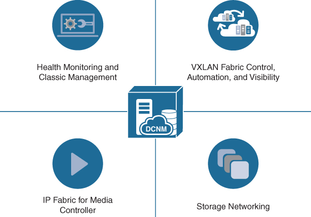
Figure 16-8 Data Center Network Manager (DCNM)
Note
There are two types of installations for DCNM: Virtual Appliance (OVA or ISO) for LAN and media operations and Standalone Installer (Microsoft Windows Server or Red Hat) for SAN operations. The LAN or Media mode is selected during deployment of DCNM from OVA or ISO.
Feature Details and Benefits
Cisco DCNM provides a robust framework and comprehensive feature set that meets the routing, switching, and storage administration needs of present and future virtualized data centers.
DCNM provides the following features for LAN Fabric with VXLAN-EVPN:
• Fabric control and overlay visibility
• Provides fabric management for multiple types of LAN solutions, including VXLAN-EVPN, Cisco Fabric Path, and traditional three-tier LAN deployments.
• Fabric Builder with PowerOn Auto Provisioning (POAP) infrastructure
• Autodetects unprovisioned switches for use in Fabric Builder.
• Includes day-0 POAP for rapid policy-based bootstrapping of fabric infrastructure.
• Includes Domain Host Configuration Protocol (DHCP) and file server functions along with best practices built in to the policy templates; ensures that deployments are consistent and properly configured.
• Easy Return Material Authorization (RMA) function from the Fabric Builder topology.
• Fabric and VXLAN compliance management
• Ensures that the network is in sync with the intended deployment and notifies when out of compliance.
• Corrects out-of-sync conditions but lets the user decide when to deploy corrections.
• VXLAN overlay management
• Intuitive overlay management, allowing deployment of SDN networking with minimal input and maximum visibility (the user can inspect the configurations that are sent to devices).
• Robust networking model using Cisco NX-OS configuration profiles.
• Built-in best practices for overlay networks are included.
• Global fabric interface manager for VXLAN fabrics
• Policy templates with built-in compliance checking.
• Customizable “show” templates.
• Top views and control
• In topology view, shows VXLAN tunnel endpoint (VTEP) status. Search allows users to visualize the extent of the VXLAN overlay in the fabric.
• Shows VXLAN network identifier (VNID) status on a per-switch basis.
• In the switch-inventory view, shows VXLAN details.
• Unified topology views
• Presents topology views showing physical and overlay networks on the same page, helping IT administrators quickly identify the extent of virtual overlay networks on a programmable fabric.
• Presents smart topology views showing virtual port channels (vPCs) and virtual device contexts for Cisco Nexus networks (topology views include VXLAN search).
• Multisite manager search, monitoring
• Provides a high-level dashboard for tracking and synchronizing data with other Data Center Network Manager deployments in remote or local data centers.
• Allows searches to query across the enterprise to locate elements that match search criteria (for example, switch, virtual machine, MAC address, or segment ID).
• Multifabric support
• Uses fabric as a managed object, allowing IT managers to keep resource pools for a given fabric separate while still using the same instance of the management tool.
• Virtual machine and Virtual Routing and Forwarding (VRF) table search
• Shows which switches contain the tenant’s virtual machine hosts or a Virtual Routing and Forwarding (VRF) table for a given tenant or organization, which helps users quickly identify where tenant traffic is located in a large fabric.
• Per-fabric pool management
• Allows pool resources such as IP addresses and VXLAN segment IDs to be allocated on a per-fabric basis.
• Role-based access control (RBAC) for fabric objects
• Allows role-based access control within the fabric to separate administrative tasks between functional domains.
DCNM provides the following features for storage networking:
• Storage topology and visibility
• Integrated device manager.
• End-to-end storage topology view from client to LUN.
• Storage networking health color coding on topology views.
• Storage bandwidth.
• Storage enclosure and virtual machine (VM) visibility.
• Telemetry and monitoring
• Provides the SAN Telemetry function (optional, licensed feature).
• Provides the Port Monitoring (PMon) configuration that allows fabric-wide deployment and customization of PMon events and actions.
• Historical trend data for SAN Inter-Switch Links (ISL).
• Alarms and event forwarding via trap and email.
• Zoning
• Provides easy-to-use web-based zoning interface to drastically reduce the cycle time for common administration tasks. Provides IVR Zoning function.
• Provides a web-based device-alias configuration to ease transition to a web-based user interface for zoning and other management tasks.
• Advanced analysis
• SAN host-path-redundancy feature to better organize and identify virtual and physical hosts with path-redundancy problems in the fabric.
• Slow-drain analysis features to increase efficiency and reduce the time to discovery for slow-drain devices.
• Storage integration
• Integration and discovery for popular storage LUN manufacturers.
DCNM provides the following features for IP Fabric for Media (IPFM):
• Flow control
• Flow and Host Policy Manager.
• Visualization and health
• Topology and endpoint visibility.
• End-to-end flow visualization.
• Network health monitoring.
• Provisioning and automation
• Fabric bootstrap: Day 0 provisioning.
• API gateway for broadcast controller.
DCNM provides the following features for automation and REST APIs:
• REST APIs
• All northbound APIs are REST. DCNM’s HTML5 GUI uses these REST APIs for all GUI functions.
• REST and JavaScript Object Notation (JSON) API
• Includes self-documented “Swagger” style built-in documentation, with examples.
• Provides easy automation mechanism for automatic fabric control using custom automation solutions.
• Enables integration with third-party or custom orchestration tools.
• Allows deployment of DCNM templates through an API for general-purpose switch updates across multiple devices in Classic mode.
• Multi-orchestrator support
• Supports orchestration through REST APIs and Advanced Message Queuing Protocol (AMQP) event notification. Operation is not restricted to a single external orchestrator, so a mixed topology is possible. Operation for traditional IP solutions is available in Classic mode.
• Automated discovery
• Using automated network discovery, provides up-to-date physical and logical inventory information.
• Tracks inventory and performance information in real time.
• Provisioning GUI, tools, and wizards
• In LAN Classic mode, DCNM provides prebuilt GUI, tools, and workflows for provisioning LAN services such as vPCs.
• Customizable templates
• Includes best-practice policy templates for Easy Fabric Mode.
• Includes Python support for complex policy templates.
• Provides prebuilt templates for bulk-capable general-purpose (Classic LAN mode) provisioning.
• Provides a prebuilt template deployment scheduler and rollback mechanism (Classic LAN mode).
• Offers customizable templates with conditional statements.
• Allows creation of new templates using a template editor.
• Allows import and conversion of configuration scripts to templates.
• Configuration and change management
• Provides predeployment validation of configuration changes to help reduce human errors (POAP includes this feature as well) (Classic LAN mode).
• Provides a general configuration archive to track changes, allowing rollback to a last-known good state (Classic LAN mode).
• Provides the capability to back up configuration files from all switches for Classic LAN mode operations (for example, non-VXLAN fabric mode).
• Software image management
• Includes Cisco In-Service Switch Upgrade (ISSU) support.
• Includes support for Graceful Insertion and Removal (GIR).
• Includes installation of SMUs and RPMs for Cisco Nexus platforms.
DCNM provides the following features for visibility, monitoring, and troubleshooting:
• Dashboards
• Provides last-24-hours summary of events and top “talkers.”
• Offers custom summary view of LAN and SAN domains and topology groups.
• Provides host, switch, and fabric dashboards.
• Allows context-based searches from dashboards.
• Provides views of configurations, events, and traffic.
• Provides interface configuration and control on switch dashboard for “Classic” mode operations.
• Topology views
• Displays topology in near-real time for data center infrastructure.
• In topology views, shows link-layer and overlay status details alongside switch details to aid troubleshooting and visibility.
• Topology overlays
• Provides general visibility into Layer 2 network connectivity mapped on the physical topology view.
• Allows users to filter topology views by overlay.
• Includes search functions for VLAN, VXLAN, VPC, and Layer 2 overlays.
• Performance and capacity management
• Provides detailed visibility into real-time and historical performance statistics in the data center.
• Provides insight into port and bandwidth use, error count, traffic statistics, and so on.
• Includes scheduled reports that can be offloaded for postprocessing.
• Health check and correction
• Health algorithm to gauge switch health.
• Autoresolves for vPC inconsistencies in Classic operations.
• DCNM server health MIB.
• Host tracking
• Tracks the details and connectivity of servers (hosts) that are connected to NX-OS devices.
• VMware visibility
• Brings the DCNM computing dashboard into the VMware vCenter for dependency mapping and inventory, performance, configuration, and event views.
• Provides topology, configuration, and information for virtual machines, port groups, DVS/vSwitches, vNICs, and VMNICs correlated with the physical network topology.
• Event management and alarms
• Provides real-time network-health summary with detailed views of individual network components, enabling operations staff to respond quickly to events based on event severity.
• Forwards syslog alerts based on a monitored facility.
• Provides stateful alarm monitoring through the alarms function to show whether an error condition is active. You can define an alarm policy for the device, interface, or syslog conditions.
• Reports
• Provides reports using predefined templates, including inventory, use, and health reports.
• Provides easy-to-schedule reports that can be exported for postprocessing or sent by email.
• Creates custom port groups related to tenants, applications, or organizations for performance reporting.
DCNM provides the following features for operations:
• Embedded database for enterprise deployments
• Does not require any external database or database administrator to manage large installations.
• High availability deployment
• Supports high availability deployment for either SAN or LAN deployments.
• Event handling/forwarding
• Integrates with the enterprise operations console (the Network Operations Center [NOC]) for alerts and events.
• Uses email messages and traps to notify operations staff of service disruptions.
• Adds context to path alerts by identifying the name of the host, Inter-Switch Link (ISL), and storage entity.
• Allows creation of custom port groups based on priority and severity level of the application and implementation of rule- based event forwarding to notify the system or user of traps and syslog messages generated for the custom port group.
Cisco DCNM Web User Interface
Cisco DCNM provides a high level of visibility and control through a single web-based management console.
A DCNM Classic LAN deployment has the following menus:
• Dashboard
• Topology
• Inventory
• Monitor
• Configure
• Administration
• Applications
A DCNM LAN Fabric deployment has the following menus:
• Dashboard
• Topology
• Control
• Monitor
• Administration
• Applications
A DCNM Media Controller deployment has the following menus:
• Dashboard
• Inventory
• Monitor
• Configure
• Media Controller
• Administration
• Catalog
A DCNM SAN Management deployment has the following menus:
• Dashboard
• Topology
• Inventory
• Monitor
• Configure
• Administration
Figure 16-9 shows the DCNM home page, which contains a navigation pane to the left and shortcuts to a few DCNM features in the middle pane.
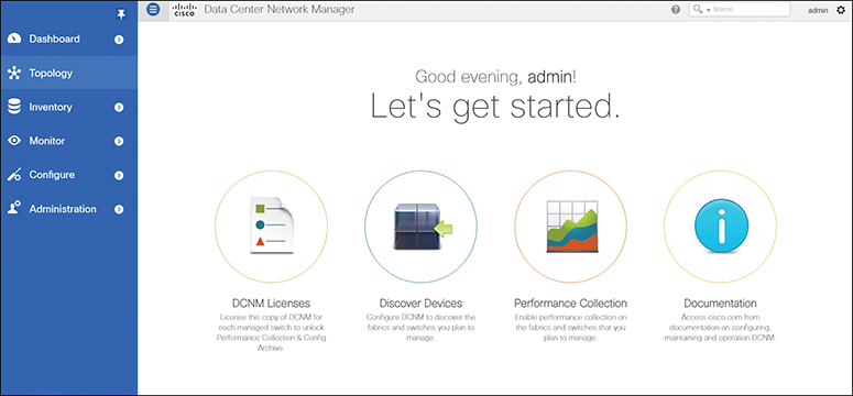
Figure 16-9 DCNM SAN Management Web Interface Home Page
The Dashboard tab enables network and storage administrators to focus on particular areas of concern around the health and performance of data center switching, as shown in Figure 16-10. This information is provided as 24-hour snapshots.
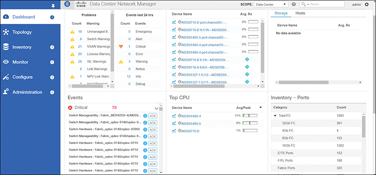
Figure 16-10 DCNM SAN Management Dashboard
![]()
Different tabs in DCNM enable the user to achieve different tasks, as explained in following list:
• The Topology tab displays color-coded nodes and links that correspond to various network elements, including switches, links, fabric extenders, port channel configurations, virtual port channels, and more.
• The Control tab is used for provisioning new fabric and managing resources and templates. You can also do real-time tracking of endpoints within a data center using the Control tab.
• The Inventory tab displays the inventory information for switches, modules, and licenses.
• The Monitor tab monitors switch information such as CPU, memory, and temperature. You can also monitor LAN performance for Ethernet, vPC, and so on, and generate reports for the same.
• The Configure tab is used for deploying configurations, managing templates, backing up configurations, and managing software images including patching and upgrading.
• The Media Controller tab is used for managing media controllers.
• The Administration tab is used for DCNM server management and users and credentials management. You can also do events managements for the errors, notifications, and so on generated on the fabric from Administration tab.
• The Applications tab is used to manage the applications used by Cisco DCNM.
Cisco UCS Director
The Cisco UCS Director is a complete, highly secure, end-to-end management, orchestration, and automation solution for a wide array of Cisco and non-Cisco data infrastructure components, and for the industry’s leading converged infrastructure solutions based on the Cisco UCS and Cisco Nexus platforms.
The Cisco UCS Director is used to perform the following tasks:
• Create, clone, and deploy service profiles and templates for all Cisco UCS servers and compute applications.
• Monitor organizational usage, trends, and capacity across a converged infrastructure on a continuous basis. For example, you can view heat maps that show virtual machine utilization across all your data centers.
• Deploy and add capacity to converged infrastructures in a consistent, repeatable manner.
• Manage, monitor, and report on data center components, such as Cisco UCS domains or Cisco Nexus network devices.
• Extend virtual service catalogs to include services for your physical infrastructure.
• Manage secure multitenant environments to accommodate virtualized workloads that run with nonvirtualized workloads.
Figure 16-11 shows that UCSD can perform end-to-end automation and life-cycle management of the IT infrastructure in the data center.
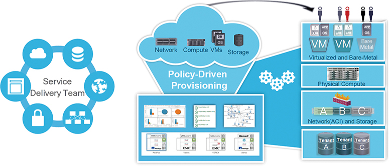
Figure 16-11 UCS Director
Note
The Cisco UCS Director installer comes as a standard virtual machine that is delivered in OVF format for VMware and in VHD format for Microsoft Hyper-V. It can be hosted on VMware vSphere or vCenter, or on Microsoft Hyper-V Manager.
Automation and Orchestration with Cisco UCS Director
The Cisco UCS Director enables you to build workflows that provide automation services, and to publish the workflows and extend their services to your users on demand. You can build Cisco UCS Director workflows to automate simple or complex provisioning and configuration processes.
Once built and validated, these workflows perform the same way every time, no matter who runs the workflows. Data center administrators can run them, or you can implement role-based access control to enable your users and customers to run the workflows on a self-service basis, as needed.
The Cisco UCS Director includes a task library containing over 1000 tasks and out-of-the-box workflows. Model-based orchestration and a workflow designer enable you to customize and automate the infrastructure administrative and operational tasks. You can extend and customize the system to meet individual needs.
With the Cisco UCS Director, you can automate a wide array of tasks and use cases across a wide variety of supported Cisco and non-Cisco hardware and software data center components. A few examples of the use cases that you can automate include but are not limited to
• VM provisioning and life-cycle management
• Network resource configuration and life-cycle management
• Storage resource configuration and life-cycle management
• Tenant onboarding and infrastructure configuration
• Application infrastructure provisioning
• Self-service catalogs and VM provisioning
• Bare-metal (BM) server provisioning, including installation of an operating system
Features and Benefits
The Cisco UCS Director has the following features:
• Central management
• Provides a single interface for administrators to provision, monitor, and manage the system across physical, virtual, and bare-metal environments.
• Provides unified dashboards, reports, and heat maps, which reduce troubleshooting and performance bottlenecks.
• Self-service catalog
• Allows end users to order and deploy new infrastructure instances conforming to IT-prescribed policies and governance.
• Adaptive provisioning
• Provides a real-time available capability, internal policies, and application workload requirements to optimize the availability of your resources.
• Dynamic capacity management
• Provides continuous monitoring of infrastructure resources to improve capacity planning, utilization, and management.
• Identifies underutilized and overutilized resources.
• Multiple hypervisor support
• Supports VMware ESX, ESXi, Microsoft Hyper-V, and Red Hat hypervisors.
• Computing management
• Provisions, monitors, and manages physical, virtual, and bare-metal servers, as well as blades.
• Allows end users to implement virtual machine life-cycle management and business continuance through snapshots.
• Allows administrators to access server utilization trend analysis.
• Network management
• Provides policy-based provisioning of physical and virtual switches and dynamic network topologies.
• Allows administrators to configure VLANs, virtual network interface cards (vNICs), port groups and port profiles, IP and Dynamic Host Control Protocol (DHCP) allocation, and access control lists (ACLs) across network devices.
• Storage management
• Provides policy-based provisioning and management of filers, virtual filers (vFilers), logical unit numbers (LUNs), and volumes.
• Provides unified dashboards that allow administrators comprehensive visibility into organizational usage, trends, and capacity analysis details.
Cisco UCS Director System Setup
The Cisco UCS Director enables you to manage both physical and virtual infrastructures. While managing a physical account, you would need to first create a site and then add a pod to the site. After you create this account, the Cisco UCS Director discovers all components within the newly created physical account. Typically, the discovery process takes about five minutes. In the system, you can either add a new pod, or you can use the default pod that is available. A physical account can be associated with the default pod or with one that you add. A managed network element is a physical account that represents a supported network device—for example, a switch, firewall, or load balancer.
You can add one or more physical accounts (computing or storage) to the pod. Choose one of the following supported computing account types for the physical account: UCSM, HP ILO, Cisco Rack Server (CIMC), or IPMI. Choose one of the following supported storage account types for the physical account: NetApp ONTAP, NetApp OnCommand, EMC VNX, EMC VMAX Solutions Enabler, or WHIPTAIL.
You can add the following types of multidomain manager accounts:
• PNSC: Cisco Prime Network Services Controller account
• DCNM: Cisco Data Center Network Manager account
• UCS Central: Cisco UCS Central account
• APIC: Cisco Application Policy Infrastructure Controller account
• EMC RecoverPoint account
• EMC VPLEX account
Note
Consult the Cisco UCS Director Compatibility Matrix for a complete list of supported devices and services.
Figure 16-12 illustrates the workflow to set up your environment using the Cisco UCS Director.
![]()
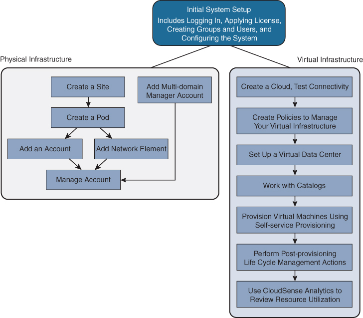
Figure 16-12 Sample Workflow to Set up an Environment using UCSD
To manage the virtual infrastructure, create virtual accounts in the Cisco UCS Director. A virtual account represents a supported hypervisor or cloud service to communicate with vCenter or Microsoft Virtual Machine Managers. The virtual account is termed cloud.
Virtual policies are created for the virtual infrastructure. A policy is a group of rules that determine where and how a new resource, be it a virtual machine or a bare-metal server, is provisioned within the infrastructure, based on available system resources.
You can self-provision VMs and bare-metal servers using predefined catalog items. Only a system administrator can create a catalog. A catalog defines parameters, such as the cloud name and the group name to which the VM is bound. You have to create and publish a catalog to make it available for use.
To provision a VM or an application using self-service provisioning, you must create a service request. The service request workflow includes allocation of required resources to the VM, approval of VM provisioning (if required), creation and provisioning of the VM, schedule VM life-cycle setup, and VM creation notification to users.
You can manage the life cycle of VMs using the Cisco UCS Director, such as powering on or off a VM, configuring lease time for a VM, and applying tags to a VM.
CloudSense Analytics in Cisco UCS Director provides visibility into the infrastructure’s resource utilization, critical performance metrics across the IT infrastructure stack, and capacity in real time. CloudSense significantly improves capacity trending, forecasting, reporting, and planning of virtual and cloud infrastructures.
PowerShell
The Cisco UCS Director PowerShell agent is a lightweight Microsoft Windows service application that acts as an interface layer between the Cisco UCS Director and the Windows machine.
You can download a PowerShell agent and install it on a Windows machine that has Windows Remote Management (WinRM) enabled. After you have started the PowerShell agent on a Windows machine, you establish a connection between the PowerShell agent and the Cisco UCS Director. This connectivity enables you to execute PowerShell scripts to automate infrastructure configuration through the Cisco UCS Director.
The PowerShell agent initiates a remote PowerShell session (PSSession) on the target server to run PowerShell commands. The target server is any Windows machine that is included in the WinRM configuration, and that the PowerShell agent can access through the default WinRM port.
When a PowerShell command is executed through a Cisco UCS Director workflow task, the following occurs:
![]()
1. The Cisco UCS Director sends the HTTP-encoded command to the PowerShell agent.
2. The PowerShell agent establishes WSMAN connections to the remote machines and then executes the commands on them.
3. The output of the command is converted to XML and sent back to the PowerShell agent.
4. The PowerShell agent terminates the connection to the target server.
5. The PowerShell agent returns the output to the Cisco UCS Director as the payload in HTTP response.
6. Other Cisco UCS Director workflow tasks can parse the returned PowerShell object information and use it as one or more variables.
Installing the Cisco UCS Director PowerShell Agent
The PowerShell agent executes cmdlets and scripts on the target server in a PowerShell remote session. To accept remote PowerShell commands, you enable Windows Remote Management, change the startup type to Automatic, create a “listener” to respond to Windows Remote Shell (WinRS) commands, and start the service on each computer you want to work with. This provides connectivity to WinRS, the client side of WSMAN protocol.
After you have enabled WinRM, download the installer for the PowerShell agent from the Cisco UCS Director to your native Windows machine. Install the PowerShell agent on your native Windows machine to enable the Cisco PSA service. The PowerShell agent is installed to the C:Program Files (x86)Cisco SystemsCisco PSA Service folder. This folder is referred to as %AGENT_INSTALL_FOLDER% in the remainder of the chapter.
Note
If you do not install the current version of the PowerShell agent for the Cisco UCS Director on the Windows machine, some tasks or options on the PowerShell agents tab are not available.
The PowerShell agent listens for incoming requests on the port specified in the properties.xml file available in the %AGENT_INSTALL_FOLDER%/props path. Configure your machine’s firewall to allow incoming TCP requests on the port specified in the properties.xml file. You have to enable inbound and outbound rules for the PowerShell agent port in the Windows machine firewall.
The final step is to copy the authkey entry for the PowerShell agent from the %AGENT_INSTALL_FOLDER%/props/properties.xml file.
After the PowerShell agent is installed and running, add it to Cisco UCS Director using Administrator > Virtual Accounts. Make sure to set up the virtual account to use the PowerShell agent for inventory collection and other management functions. In the virtual account details, you will configure name, IP/FQDN, port, and authkey of PowerShell agent.
At this stage, you can check the connectivity between the Cisco UCS Director and the PowerShell agent.
After you have added the PowerShell agent to the Cisco UCS Director, you can set the authentication mechanism by creating a workflow with the Execute PowerShell Command task.
Executing PowerShell Agent Commands
PowerShell commands are used for executing workflows on a target server. The Cisco UCS Director offers the following two types of command tasks:
• Execute PowerShell Command Task
• Execute Native PowerShell Command Task
The Execute PowerShell Command Task can run PowerShell scripts only on a remote server. When a command is executed, the PowerShell agent opens a remote PowerShell connection (PSSession) to the target server. Scripts are then executed on the target server. The connection is closed when the execution is complete.
Note
PowerShell scripts may fail if your environment has a multihop delegation and you have not enabled the CredSSP protocol in your infrastructure. Multihop support in WinRM uses CredSSP for authentication. CredSSP lets an application delegate the user’s credentials from the client to the target server for remote authentication. The failure occurs because the scripts that are executed remotely cannot connect to other Windows machines.
Figure 16-13 provides an overview of the Cisco UCS Director PowerShell agent.
![]()
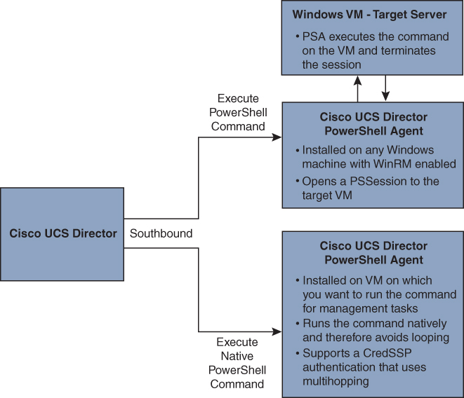
Figure 16-13 Overview of Cisco UCS Director PowerShell Agent
The Execute Native PowerShell Command Task creates a native PowerShell instance on a Windows machine and executes the scripts natively on the PowerShell agent. As a result, the target scripts are not sent over a remote WinRM session for execution. They are run locally on the PowerShell agent. This feature allows you to bypass the limitations encountered when the scripts are run in a PSSession using the Execute PowerShell Command Task. All the functionality offered by the PowerShell console is available through this task.
Exam Preparation Tasks
As mentioned in the section “How to Use This Book” in the Introduction, you have a couple of choices for exam preparation: the exercises here, Chapter 20, “Final Preparation,” and the exam simulation questions in the Pearson Test Prep software online.
Review All Key Topics
Review the most important topics in the chapter, noted with the key topic icon in the outer margin of the page. Table 16-7 lists a reference to these key topics and the page numbers on which each is found.
![]()
Table 16-7 Key Topics for Chapter 16

Memory Tables
Print a copy of Appendix C, “Memory Tables” (found on the companion website), or at least the section for this chapter, and complete the tables and lists from memory. Appendix D, “Memory Tables Answer Key,” also on the companion website, includes completed tables and lists to check your work.
Define Key Terms
Define the following key terms from this chapter, and check your answers in the Glossary.
Extensible Markup Language (XML)
JavaScript Object Notation (JSON)
YAML Ain’t Markup Language (YAML)
RPM Package Manager (RPM)
NX-API
Cisco UCS Manager SDK (UCSMSDK )
Rubygems
Management Information Base (MIB)
Management Information Tree (MIT)
managed object (MO)
multitenancy
network interface card (NIC)
Network Time Protocol (NTP)
orchestration
Ethernet VPN (EVPN)
VXLAN tunnel endpoint (VTEP)
Virtual Extensible LAN (VXLAN)
VXLAN network identifier (VNID)
domain-specific language (DSL)
application programming interface (API)
Advanced Message Queuing Protocol (AMQP)
Graceful Insertion and Removal (GIR)
Software Maintenance Upgrade (SMU)
Distributed Virtual Switch (DVS)
Elastic Sky X integrated (ESXi)
Cisco Integrated Management Controller (CIMC)
Cisco MDS
Cisco NX-OS
Open Agent Container (OAC)
Intelligent Platform Management Interface (IPMI)
WHIPTAIL
VNX
VPLEX
Cisco Data Center Network Manager (DCNM)
Dynamic Host Configuration Protocol (DHCP)
RecoverPoint
Prime Network Service Controller (PNSC)
PowerOn Auto Provisioning (POAP)
PowerShell agent (PSA)
Preboot Execution Environment (PXE)
Simple Network Management Protocol (SNMP)
Unified Computing System (UCS)
UCS Manager (UCSM)
Integrated Lights-Out (iLO)
Windows Remote Management (WinRM)
Windows Remote Shell (WinRS)
PowerShell session (PSSession)
Web Services-Management (WSMAN)
Credential Security Support Provider Protocol (CredSSP)
Git/GitHub
graphical user interface (GUI)
Hypertext Transfer Protocol (HTTP)
hypervisor
Inter-Switch Link (ISL)
in-service software upgrade (ISSU)
virtual interface card (VIC)
virtual LAN (VLAN)
virtual machine network interface card (VMNIC)
virtual network interface card (vNIC)
virtual port channel (vPC)
Virtual Routing and Forwarding (VRF)
workflow
Workflow Designer
Domain Name System (DNS)
software development kit (SDK)
References
Ansible Documentation: https://docs.ansible.com/ansible/latest/index.html
Cisco Devnet: https://developer.cisco.com
Data Center GitHub: https://github.com/datacenter
Cisco GitHub: https://github.com/cisco
Cisco UCS GitHub: https://github.com/CiscoUcs
Cisco Nexus 9000 Puppet Solution: https://www.cisco.com/c/en/us/products/collateral/switches/nexus-9000-series-switches/solution-brief-c22-730039.html
Cisco Nexus 5000 and 6000 Series NX-OS Programmability Guide: https://www.cisco.com/c/en/us/td/docs/switches/datacenter/nexus5000/sw/programmability/guide/b_Cisco_Nexus_5K6K_Series_NX-OS_Programmability_Guide.html
Cisco Nexus 9000 Series NX-OS Programmability Guide, Release 9.2(x): https://www.cisco.com/c/en/us/td/docs/switches/datacenter/nexus9000/sw/92x/programmability/guide/b-cisco-nexus-9000-series-nx-os-programmability-guide-92x.html
Cisco Nexus 7000 Series NX-OS Programmability Guide: https://www.cisco.com/c/en/us/td/docs/switches/datacenter/nexus7000/sw/programmability/guide/cisco_nexus7000_programmability_guide_8x.html
Cisco Nexus 9000 Series NX-OS Fundamentals Configuration Guide, Release 9.2(x): https://www.cisco.com/c/en/us/td/docs/switches/datacenter/nexus9000/sw/92x/fundamentals/configuration/guide/b-cisco-nexus-9000-nx-os-fundamentals-configuration-guide-92x.html
Cisco Nexus 7000 Series NX-OS Fundamentals Configuration Guide: https://www.cisco.com/c/en/us/td/docs/switches/datacenter/nexus7000/sw/fundamentals/config/cisco_nexus7000_fundamentals_config_guide_8x.html
Cisco Nexus 5500 Series NX-OS Fundamentals Configuration Guide, Release 7.x: https://www.cisco.com/c/en/us/td/docs/switches/datacenter/nexus5600/sw/fundamentals/7x/b_5600_Fund_Config_7x.html
Cisco Data Center Network Manager 11 Data Sheet: https://www.cisco.com/c/en/us/products/collateral/cloud-systems-management/prime-data-center-network-manager/datasheet-c78-740978.html
Relevant Cisco Live Sessions: http://www.ciscolive.com
Cisco UCS Director Getting Started Guide, Release 6.5: https://www.cisco.com/c/en/us/td/docs/unified_computing/ucs/ucs-director/getting-started-guide/6-5/cisco-ucs-director-getting-started-65.html
Cisco UCS Director PowerShell Agent Installation and Configuration Guide, Release 6.7: https://www.cisco.com/c/en/us/td/docs/unified_computing/ucs/ucs-director/powershell-guide/6_7/cisco-ucs-director-psa-install-config-67.html