Chapter | twenty
Multi-Channel and Surround Sound
CHAPTER OUTLINE
Dolby® Stereo & Dolby® Surround
Loudspeaker Positioning – Dolby® Surround
Digitally-Based Multi-channel Systems
Dolby® Stereo SR•D/Dolby® Digital
SDDS® (Sony Dynamic Digital Sound)
Display of Matrix-Encoded Signals
Phase Differences between Adjacent Channels
Acoustic Calibration of Multi-channel Systems
Calibration of 5.1 in an ITU-775 Arrangement
Other Systems for Surround Sound
Audio using more than two channels is standard in many areas, such as audio productions for TV, the cinema, the home cinema, the car, and music formats for Hi-Res CD, DVD, Blu-Ray, and audio formats for computer-based games.
These formats involve sound using four to eight channels. Certain formats are stored and transmitted in just two channels, and are “unpacked” when they are listened to. Other formats are produced as discrete channels, but are stored and transmitted digitally as a single bit stream. Furthermore, concepts such as “virtual surround” exist where only two channels are used and these channels give the impression that there is sound all the way around the listener.
In order to know what means are available for monitoring signals, the way in which most important formats work will be described here. Emphasis will be placed on the matrix-encoded formats and their principles, due to the fact that these are quite widespread in the multimedia area. We will also look at the relation between the signal levels on tape, film, and hard disk, and look at the associated acoustic sound levels.
MATRIX-ENCODED FORMATS
The matrix-encoded formats are characterized by four or five channels being mixed down to two. A network mixes the signals in a manner that permits their separation again although this is not possible under all conditions.
The principle is also called 4:2:4 or 5:2:5, which indicates how many channels are produced, how many are stored or transmitted and finally how many channels the format is reproduced in. The most widespread systems are Dolby Stereo (or Dolby Surround), which is a 4:2:4 system. Others include Circle Surround, 5:2:5, and Lexicon Surround, 4:2:5 or 5:2:5.
DOLBY® STEREO & DOLBY® SURROUND
Dolby Stereo and Dolby Surround are two sides of the same coin. Dolby Stereo is the original name for the matrix-encoded audio signals found on the two optical sound tracks of cinema films. Here, noise reduction is also used, either Dolby A or Dolby SR. Dolby Surround uses the same matrix system as Dolby Stereo, only without the noise reduction, and is found on consumer formats.
The principle of Dolby Stereo/Dolby Surround is that four channels, namely left, center, right, and surround are matrix-encoded down to the two channels that are subsequently called Lt (Left total) and Rt (Right total). These two channels are recorded on the two sound tracks of the films. When they are played back through the cinema’s processor or the home system’s Pro Logic decoder, the four channels are re-established.
A surround-encoded signal can also be listened to in normal stereo and in mono; however, without the benefits of the larger sound image. With stereo reproduction, all the information is present, only it is reproduced in the stereo system’s two channels. In mono, the part of the signal that would have been reproduced in the surround channel disappears.
Dolby Surround has been made into a production format, not just for radio and TV sound, but also for CD releases, and in particular for sound in computer games. Even if you are not producing in the format, it is important to know how an arbitrary stereo production will be played back in the system since this often occurs.
Encoding
The simplest part of the process is the encoding. The principles the encoder operates under are as follows:
- Left is run directly to Lt.
- Right is run directly to Rt.
- Center is attenuated by 3 dB and then added in phase equally to Lt and Rt.
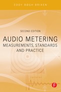
The surround channel is attenuated by 3 dB, band-pass filtered (f1 = 100 Hz, fu = 7 kHz), and low-level compression is added (modified Dolby B), passed through a 90° phase-shifting circuit, and run to Lt and Rt respectively in antiphase.
The purpose of the 90° circuit is to make it possible to pan between center and surround. If it is not done in this manner, then the sound will go through half of the pan and end in either the left or right channel.
Mix & Mic
During the mixing process, attempts are normally made to use signals in the four channels that are uncorrelated in order to obtain the best possible channel separation in the subsequent decoding.
The stereo microphone technique that comes closest to producing a signal that corresponds to a matrix-encoded signal is the MS technique. There is a good correlation between the placement of the sound sources at the recording and the playback in matrix-encoded systems such as Dolby Surround, Circle Surround, and Lexicon Surround.
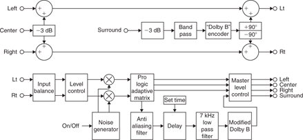
FIGURE 20.1 Schematic diagram for Dolby Surround encoding (top) and Pro Logic decoding (bottom). The simplest part is the encoding of left, center, and right since this can be done on any stereo mixer. The surround channel however must be inserted at ±90° due to a requirement of direct panning between center and surround.
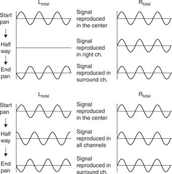
FIGURE 20.2 Upper: Panning from center to surround without use of 90° phase shifting. Halfway through the panning, the signal will lie in one of the side channels, here the right channel. Lower: Panning from center to surround with use of 9090° phase shifting. Halfway through the panning, the signal lies in all channels. This is heard as the signal gradually disappearing out of the center and appearing in surround.
Decoding, Passive
In the simplest form of passive decoding that is found on certain sound cards, the four channels are created in the following manner:
Left = Lt
Right = Rt
Center = (Lt + Rt) −3 dB
Surround = (Lt + Rt) −3 dB
This decoding is very imprecise due to poor channel separation, but it can, however, create a certain spatial effect.
Decoding, Pro Logic
With Pro Logic decoding, a procedure is undertaken based on the mutual level and phase relationships of the Lt and Rt signals, which causes signals that were solely represented in a single channel prior to the encoding to also appear only in that single channel after the decoding. For example, all center information will be removed from the left and right channels, all left information will be removed from center and surround, etc.
Before the surround information is sent out, the signal will be delayed (adjustable 20–100 ms) to take into account the Haas effect, thus avoiding localization to the rear speakers, which are typically placed closest to the listener. Then lowpass filtering is performed at 7 kHz in order for small phase errors in the transmission to not result in audible crosstalk in the channel. Finally, a noise reduction is performed in a circuit that corresponds to partial Dolby B with half effect (half expansion). The circuit affects signals below approxinately –20 dB.
The Pro Logic decoder is fitted with a pink noise generator for adjusting the channel balance. Adjustments are made to the same level for each channel, measured at the listening position. All (both) surround speakers are counted as one channel.
The Pro Logic II decoder has been developed with the particular purpose of creating surround sound from normal stereo productions.
Important Details
The following details are important for the production and use of Dolby Surround to be able to judge levels correctly:
- It is important that all program material that may be decoded through a Pro Logic decoder is auditioned through one. Many stereo effects rely on relative phase effects and will thus end up in the surround channel.
- A 100 Hz bass cutoff occurs in the surround channel only in the encoder, not in the decoder.
- If Lt and Rt are mutually phase-shifted by 90°, but are otherwise at the same level, then the signal will distribute itself equally in all four channels.
- When mixing surround programs, the four channels must always be monitored via an encoder and decoder so that the spatial steering effects of the latter may be recognized and compensated for.
- Surround decoders for home use (Pro Logic) use a special terminology: Normal: Bass under approximately 100 Hz is filtered out from the center channel and distributed in the right/left channel (so one can use a center speaker with limited bass capabilities). Wide: All three front channels have full frequency range.
- In many computer-based games, Dolby Surround is used since the format is supported by a number of sound cards. Typically, a setup without a center speaker is used. In consumer decoders, this corresponds to phantom center, where the entire center signal is equally distributed to the left and right channels.
Loudspeaker Positioning – Dolby® Surround
The basic loudspeaker setup for Dolby Surround has three front speakers e left, center, and right. Normally, the center speaker is placed under the picture monitor, and if projection is used the speaker is placed behind the screen.
The surround channel is normally reproduced over two speakers placed diagonally behind the listener. In order to avoid the perception that the sound from the rear speakers is coming from a point between the two speakers, the signal to one of the speakers may be either phase-shifted or phase-inverted. When mixing in a small room, phase-inverting one of the surround speakers is not recommended as it will then be very difficult to judge the level in this channel. However, a 90° phase shift will work. In THX-specified systems for home use, it is possible to use dipole speakers to attain diffuse sound.
Acoustic Calibration
The decoder’s pink noise generator is used in acoustic calibration. The electrical signal lies at −6 dB in relation to full modulation. Each channel is measured on its own. All speakers in the surround chain are regarded as one channel. In the listening position, a sound pressure level of 82 dB(C) is measured from each channel.
In a cinema (Dolby Stereo), the measurement is made over a larger area; typically four to five characteristic measurement points are selected. The sound from each channel is then measured at these points and the result is an average of the measurements. Instead of a test generator, a special test film is used with pink noise recorded at −6 dB.
FIGURE 20.3 A: Dolby® Surround. Center mode: Wide. B: Dolby® Surround. Center mode: Normal (reduced frequency range in the center channel). C: Dolby® Surround. Center mode: Phantom (center is split between left and right channel). D: Dolby® Surround. The surround speakers are dipole speakers.
Pro Logic Decoders
Dolby Laboratories has granted a Pro Logic license to a number of manufacturers who produce processors. All Pro Logic circuits are approved by Dolby. Regardless, there are significant differences in the sound quality depending on which supplier has produced the processor concerned. The professional decoders and a more musical consumer version, Pro Logic II, are all produced by Dolby Labs itself.
CIRCLE SURROUND®
Circle Surround is another of the matrix-encoded systems, and is a 5:2:5 system. As opposed to Dolby Surround, this involves a system that splits the surround channel up into left and right surround. The format can also reproduce Dolby Surround encoded material.
LEXICON LOGIC7™
Lexicon has developed a decoder that is capable of extracting seven channels out of two. The system is primarily developed for music and has been introduced for car audio systems with three front channels, left and right surround/side and left and right back.
Digitally-Based Multi-channel Systems
While the matrix-encoded formats mainly build on analog technology, there is another group of more or less true multi-channel systems that are based on digital technology. What they have in common is that the channels are kept separate during the entire production phase until they are presented to the user. Here, they are packed together – sometimes with the use of bit reduction e into a single bit stream. The systems are used both for film sound in cinemas and for film and music production for listening in the home.
THE 5.1 FORMAT
Even though several other formats exist, most multi-channel sound production formats are based on the standardized 5.1 loudspeaker arrangement. The number refers to the fact that there are five channels with a full 20 Hz – 20 kHz bandwidth. In addition, there is one channel for sound effects at low frequencies. This channel is normally called the LFE channel (Low Frequency Enhancement or Low Frequency Effects). It has only a limited frequency range. Tomlinson Holman hence called it “.1” (even though the frequency range is less than 1/10 in comparison with the other channels). This name has stuck and it has subsequently been included in standards and similar official writings. It does not involve an actual subwoofer channel or the like, because all primary channels go all the way down to 20 Hz. However, this LFE channel is amplified 10 dB more than the other channels to provide additional headroom. It may only be used for a bang that occurs once, half an hour into the program material.
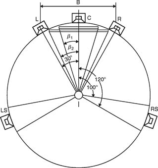
FIGURE 20.4 Listening setup according to ITU-R BS.775-1.
The LFE or “.1” channel is included due to regard for the better utilization of the dynamic range of the primary channels. In general, it is used mostly in movies and only extremely rarely in music.
This configuration is also called 3/2 because there are three front channels and two rear channels. If the front speakers are in a row, it is suggested by the ITU that the center speaker is given a time delay. The LFE (or .1) channel has not been taken into account in this arrangement. The subwoofer can in principle be placed anywhere with appropriate regard paid to distance and acoustic conditions in the room.
Dolby® Stereo SR•D/Dolby® Digital
Dolby Stereo SR•D is a sound format on 35 mm film. It contains both analog and digital sound. The analog sound is encoded in Dolby Stereo with Dolby SR (Spectral Recording) noise reduction. The digital sound is encoded in Dolby Digital 5.1. The bit reduction system is Dolby AC-3 with a bit rate of 320 kbps. The LFE channel encompasses the frequency range 20 Hz – 120 Hz.
During playback in a cinema, a change can be made from the digital to the analog tracks if errors occur in the scanning of the digital information. On DVDs, Dolby Digital is used as one of the standardized formats, both on DVD-Video and DVD-Audio.
Surround EX
In connection with the recording of “Star Wars – Episode 1” Dolby and THX/ Lucasfilm felt a need for an extra rear channel that could be introduced without any large technology-related problems. The center-surround channel is encoded into left surround and right surround using the same method used for the encoding of the center channel in Dolby Surround. The digital encoding and decoding remain unchanged in relation to Dolby Digital.
DTS® (Digital Theater System)
This format was, as the name suggests, developed by Digital Theater System, an American company. The bit reduction system used, Apt-X, was however developed in Ireland. The reduction has a fixed ratio of 4:1 (i.e., only 25% of the original quantity of bits remains). It is fundamentally a 5.1 format used both for film sound and music production. In both cases, the digital information is placed on a CD-ROM. The consumer version is called Digital Surround.
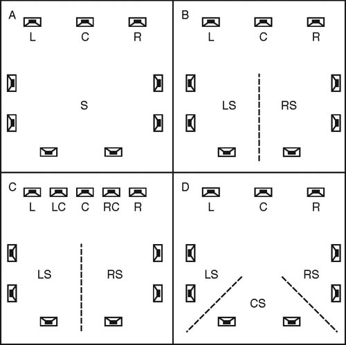
FIGURE 20.5 A: Dolby® Stereo (analog and matrix-encoded format). Configuration: 3/1 (three front and one rear channel). B: Dolby® SR•D (Dolby® Digital) and DTS (Digital Theater Systems). Configuration: 3/2. C: SDDS (Sony Dynamic Digital System). Configuration: 5/2. D: Surround EX™ and DTS ES. Configuration: 3/3.
Arrangements as they occur in a cinema are as follows:
For normal feature films, DTS uses two CDs, which makes for a total feature length of 3 hours and 20 minutes. A timecode is printed alongside the analog sound tracks on the film. This timecode is used for synchronizing the CDROM player and projection machinery. The LFE channel here encompasses the 20 Hz – 120 Hz frequency range. The first film with DTS was Jurassic Park.
DTS-ES (Extended Surround)
DTS found it necessary to follow suit when Dolby developed Surround EX. Hence DTS is also able to offer a format with a center surround channel.
SDDS® (Sony Dynamic Digital Sound)
SDDS has eight channels: left, right, center, left center, right center, left surround, and right surround, and an LFE channel. It is a 7.1 format. SDDS differentiates itself from 5.1 by the fact that it uses two additional speakers placed between left and center and center and right. The system can, however, also function in 5.1 or 4/1, or 3/2 formats.
The bit reduction system is ATRAC (Sony’s own), which is also used on MiniDisc. The compression is approximately 5:1. The maximum bit rate is 1411 kbps. SDDS is used only for films. The digital information is placed on the film itself.
DIGITAL CINEMA
The goal for the Digital Cinema is the establishment of completely file based formats to be distributed by data networks. Many cinemas have been refurbished to accomplish this goal. However, it has also been an investment to follow the trend. Actually in many countries the picture may have been improved by the transition to file based films. However, the play out sound systems have unfortunately gone from 5.1 to 4:2:4 matrix formats.
DISPLAY OF MATRIX-ENCODED SIGNALS
The two channels containing matrix-encoded signals can be monitored on normal stereo instruments. The goniometer is particularly useful because it can show whether the phase angle is too wide, etc. The goniometer is incredibly efficient when it comes to the quick overview. It is also important to monitor the balance between the Lt and Rt channels. Even though most decoders are relatively effective in maintaining a center impression, imbalance may result in an incorrect division of the channels. It is also possible to use an instrument with a built-in surround decoder.
VIRTUAL SURROUND
Virtual surround is a set of techniques where only two speakers or a set of headphones are used to recreate a sound field from many speakers. The effect is often arbitrary. The surest way to monitor signals is to use the goniometer since the signals typically have high phase opposition content.

FIGURE 20.6 This shows one manner of displaying the content of a surround-encoded signal. The signal is strongest in the “most full-bodied” direction. This display is popularly called a “Jelly Fish™.” At the same time, the bar graph meter shows the precise channel level. This instrument, the MSD600, can display both Pro Logic and true multi-channel audio.
DISPLAY OF 5.1
With true 5.1 or the equivalent, the channels will be kept separate prior to the final coding into one of the standardized formats. Six bar graph meters can of course show what the individual channels contain. However, it is most practical and more manageable to use an instrument with a Jelly Fish™-like display.
Jelly Fish
Jelly Fish™ from DK Technologies is the popular – and registered – name for a goniometer-like display on a screen.
The figure in itself does not show the phase between the channels, but rather the amplitude in each of the channels concerned. The purpose of this display is to create an overview.
If the incoming signal is matrix-encoded, a decoding is performed first of Lt and Rt so that the resultant channels are obtained. If it is true multi-channel, then the signals are used directly. On the instrument’s screen, a circle is fundamentally established and the magnitudes of the levels in the channels concerned (left, center, etc.) are multiplied into this figure. The figure thus becomes the “most fullbodied” in the direction/channel that has the strongest signal. For the sake of clarity, the instrument will normally have a certain inertia in order for the user to be able to follow that part of the signal that has a certain weight in terms of time.
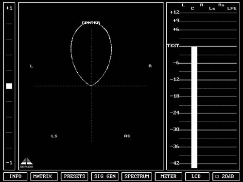
FIGURE 20.7 Jelly Fish™: signal solely in the center channel.
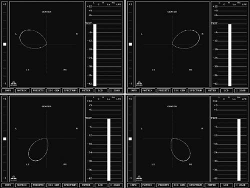
FIGURE 20.8 Upper:Jelly Fish™: signal solely in the left and right front channels. Lower: Jelly Fish™: signal solely in the left and right surround channels.
Phase Differences between Adjacent Channels
Since the figure does not show anything about the phase, Jelly Fish™ provides a change of color in the transition area between two channels if the phase angle is greater than 90°.
ACOUSTIC CALIBRATION OF MULTI-CHANNEL SYSTEMS
Calibration of the acoustic sound levels has been a requirement for many years when working with sound for film, although it has not been particularly common in other branches of the sound industry. However, with the widespread use of multi-channel formats for all forms of music and film presentation in the home, it has turned out to be beneficial to also calibrate the acoustic levels for these formats.
It is important to differentiate between production for the cinema and production for 5.1 channel reproduction in the home based on ITU 775.
CALIBRATION OF CINEMA SYSTEMS
In a cinema, the listeners sit far from the speakers. Presumably, the majority sit in the diffuse sound field. In any event, attempts are made to establish a diffuse sound field from the surround speakers. Thus, when the sound pressure is measured inside the cinema or in a mixing theater it must be averaged over many different measurement locations. The typical basis for the majority of standards is at least four locations. If there are different areas for the audience, for example main floor and balcony, measurement should be made in at least four locations in each.
Before performing this measurement, the system’s frequency response must be in order. Normally, the ISO 2969 X curve standard is used as a measure for the characteristics of the system.
Optical Sound
Cinema systems for the reproduction of Dolby Stereo (analog optical sound), normally have a built-in generator with pink noise. This signal is sent out at a level corresponding to half modulation of the optical track (i.e., 6 dB below full modulation).
The generator is used in particular in the mixing theater, where the sound has of course not hit the recording media yet. With this, the B chain can also be checked; that is, that portion of the sound system that encompasses everything from the playback system for the specific cinema up to and including the acoustic space. (The A chain encompasses that portion of the system that lies before the playback system for the specific cinema.)
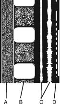
FIGURE 20.9 A: SDDS (corresponding tracks are found on the opposite edge of the film). B: Dolby Digital. C: Analog sound tracks. D: DTS sound tracks on 35 mm film.
A test film (Dolby cat. No. 69) with prerecorded pink noise at 6 dB under full modulation and with Dolby noise reduction is run in the cinema’s projector in order to assist in making adjustments to the B chain. For each of the four channels (L, C, R, and S) adjustments are made for a sound pressure level of 85 dB(C) (integration time: slow) in the inside of the cinema as calculated by a simple average value of the measurement results at the selected measurement locations. This procedure regards a chain of surround speakers as one channel (i.e., all the speakers in this chain must be operating at the same time).
Digital Sound
Digital sound on film has created a larger dynamic range, of which a large part is used for greater headroom in comparison with optical sound.
The digitally recorded SMPTE standardized test signal (pink noise) lies at –18 dBFS. During playback of each of the front channels, this signal must be reproduced at a sound pressure level of 85 dB(C). The two surround channels are each adjusted to 82 dB(C). This causes the level created by the entire surround chain to thus equal 85 dB(C).
A 10 dB amplification is inserted in the playback chain for the LFE signal. When the limited bandwidth (20 Hz – 120 Hz) pink noise from the LFE channel is played back, it is possible with a 1/3-octave spectrum analyzer to see that the individual ranges in the LFE channel are reproduced 10 dB higher than the individual ranges in each main channel. Measured as a Cweighted sound pressure level, the LFE channel will show a level that is approximately 4 dB(C) higher than the level in each main channel.
CALIBRATION OF 5.1 IN AN ITU-775 ARRANGEMENT
In a 5.1 system based on the ITU arrangement, all main channels have in principle the same conditions: there is one speaker per channel and each is placed the same distance from the listener.

FIGURE 20.10 The spectrums are shown here for pink noise recorded on LFE (on the left) and on a main channel (on the right). The LFE only goes to 120 Hz, whereas the main channel has full bandwidth. All columns in the active areas of the channels are of equal height (i.e., the channels have the same level per 1/3-octave). The column furthest to the left in each spectrum shows the total level. The level is 6 dB lower in the LFE channel than in the main channel. This is because there is a smaller frequency range represented here.
Internationally, there is however agreement neither on the level nor on the bandwidth for the noise signal that is used for acoustic calibration. Pink noise is good since it includes all frequencies; however, it is impractical due to its “unsettled” character, which makes it difficult to measure at low frequencies.
SURROUND SOUND FORUM
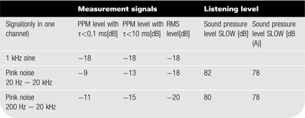
Surround Sound Forum (SSF) is a German interest group established by Verband Deutscher Tonmeister (VDT, Association of German Tonmeisters), the Institut f ür Rundfunk Technik (IRT, Institute of Broadcast Engineering), and Schule f ür Rundfunktechnik (SRT, School of Broadcast Engineering). The SSF has prepared guidelines that are generally accepted in Europe. Three test signals are specified in it, which are recorded at –18 dBFS (RMS).
TABLE 20.1 Measurement signals for the main channels in surround sound configuration
SMPTE
The corresponding standard from SMPTE (RP155) uses a standard of –20 dBFS for the reference level. Here, the C-weighted sound pressure level ends up at 83 dB.
BASS MANAGEMENT
Bass management consists primarily of filtering out the bass from the main channels and reproducing it in a subwoofer (together with the LFE signal). Frequency response and level must display the same data as if only full range systems were being used in the main channels.
OTHER SYSTEMS FOR SURROUND SOUND
New systems are being developed all the time. Some of these systems are intended for commercial use in the home and other systems are more likely to be used in a fixed installation in venues for theater, special events, etc.
TMH 10.2 is a system developed and demonstrated by Tomlinson Holman. It involves speakers over the head.
NHK 22.2 is a Japanese system developed by the national broadcaster with 24 audio channels intended for broadcast. It has been demonstrated and programs have been made for this format.
Sound Field Synthesis is being developed and promoted mainly in the Netherlands by Diemer de Vries and his team at the Delft University. The system recreates the soundfield. One system can easily consist of 64 channels.
UPMIXING SYSTEMS
Most software based mastering tools include algorithms to upmix from stereo to surround, both 5.1 and 7.1. This has been a necessity in order to provide content for the many systems found on the market. These algorithms are not all alike and must be assessed in connection with the program material to be converted.