Chapter | twenty-four
Where to Connect a Meter
CHAPTER OUTLINE
Connections via a Jackfield (Patchbay)
The Instrument as a Measurement Device
Loudspeaker/Headphone Monitoring
A level meter can be used at various points of the signal chain.
ANALOG CONNECTION
Before selecting points where the instrument is to be inserted, it is worthwhile to look at a couple of fundamental concepts concerning measurement technique. One must know whether the connection of the measurement instrument will have an influence on the measurement itself. The keywords here are voltage matching and impedance matching.
VOLTAGE MATCHING
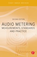
A basic electronic circuit showing the output of a device connected to another device (a level measuring instrument in this case) is displayed in Figure 24.1.
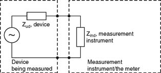
FIGURE 24.1 The connection between two devices can be viewed as a division ofvoltage between the source impedance (Zout) and the input impedance (Zin).
The rule is that the largest voltage is found across the largest resistance or impedance. If measuring the magnitude of the output signal of the “device,” then it is necessary that the measurement system not load the output. Therefore, the input impedance must be high compared to the source impedance. A good rule of thumb says that the input impedance in the measurement system must be at least 10 times that of the output impedance of the device that is being measured. This applies as long as we are dealing with LF (low frequency), i.e., when we are in the audio spectrum below 20 kHz and the cable lengths are less than a few hundred meters/yards.
A typical example: The output impedance of a mixer’s line output or auxsend can be 100–200 Ω. The input impedance of the analog input of a measurement instrument (in this case from DK-Technologies) is specified to be >20 kΩ. The input impedance is at least 100 times higher than the output impedance; thus the measurement instrument will display the correct signal voltage on the output concerned.
IMPEDANCE MATCHING
When dealing with LF in cables with lengths in kilometers/miles and for HF (high frequency), for example when handling video signals, antenna signals, digital audio signals, etc., there is a need for impedance matching. Impedance matching means that the source impedance and the load impedance must be equal. If there is an impedance mismatch, reflections and signal degradation will occur in the cable.
The consequence of impedance matching is that the signal becomes equally divided between the two impedances in terms of voltage. In other words, there is half of the voltage over each. In order to measure the correct level with a measurement instrument with high input impedance, the output that requires impedance matching must be terminated correctly, i.e., loaded with the nominal impedance. If this is not the case, the measurement instrument will show a value that is up to 6 dB too high. If, for example, an output is specified +4 dBm, it refers to the fact that the signal is 1.23 V, although generally only when the output is terminated with 600 Ω.
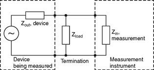
FIGURE 24.2 Impedance matching: The level is measured correctly when the output is terminated (loaded) with the nominal impedance. Without loading, double the voltage will be measured when the measurement instrument exhibits high input impedance.
THE MIXING DESK
The need for level measurement arises first and foremost when controlling levels with the sound mixing desk.
Inputs The signals in the inputs are at a microphone or line level. Here, an overloading indicator is of primary importance. Each channel must be driven optimally, but without overloading.
Master outputs (main out) Here, it will always be natural to measure the levels relating to the driving of the downstream step: recording media, transmitter, PA system, etc.
Group outputs (group out), aux and bus outputs Larger audio mixers will normally either provide meters on these outputs or include the option to allocate one or more instruments for this purpose.
Insert points and aux-return Here, it will be less common for a meter option to be built into the mixer. It can therefore be beneficial to have the instrument( s) connected to a patch panel, so that it is possible at any time to monitor whether the return channels are also appropriately driven.
There can be a difference between the nominal levels at different places in the mixer. Because the level at the insert points may be lower than the group and master outputs, it is a good idea to be familiar with the mixer’s level diagram.
OUTPUTS WITH EMPHASIS
Often the level meter will be used to measure a signal that will subsequently be emphasized, i.e., corrected in certain parts of the spectrum. One example involves the output from a radio station that will subsequently be connected to an FM transmitter. Here, pre-emphasis is performed by raising the treble. Upon reception, the treble is lowered correspondingly. Aform of noise reduction is attained by doing this (see the discussion on emphasis curves in Chapter 9). A second example involves an audio signal that is transmitted by satellite, where the J.17 standard is used. Emphasis can even be involved in the use of digital media. AES/EBU includes the possibility for signaling using two different standards, and S/PDIF includes the possibility for one.
FIGURE 24.3 An example of a level diagram for an analog sound mixer.
Most emphasis curves were developed when it was not particularly common to have extreme modulation in the treble. Today, the problem can be that, even though a great deal of care has been taken in keeping the level under the applicable limits, the emphasis can still cause the transmission line to be overloaded, precisely because of the raising of the treble. Quite literally, one can risk burning the FM transmitter out or having the satellite transmission drop out.
In order to protect against accidents it is thus not just an advantage, but rather a necessity to be able to connect an instrument after the emphasis. In the same regard, this also holds true for the program limiter, i.e. the limiter that normally sits on the output as protection against overloading.
BALANCED/UNBALANCED
In order to run an electrical signal from one device to another, two wires must be used. Otherwise a circuit is not established. In a balanced connection, these conductors are physically identical. The shielding around the conductors can comprise a third wire though this is not included in the signal path. In an unbalanced connection, there is one conductor involved that is “hot” and the shielding is then used as the other conductor in the circuit. The shielding and hence the chassis are part of the signal path.
When the meter is connected to the output it can occur in some instances that the reading is not what one expected. On the following pages different situations are described.
Unbalanced Out/Unbalanced In
In an unbalanced connection, the correct level is in principle always being measured. There can, however, be unfortunate situations in which there might be problems with low-frequency noise (hum) if both systems are connected to ground via, for example, the power plug. A low-frequency noise loop can arise in the earth/frame/shielding circuit.
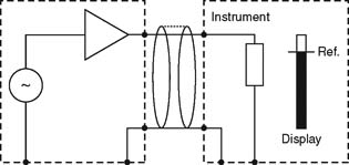
FIGURE 24.4 Unbalanced output; unbalanced input.
Unbalanced Out/Balanced In
The connection can be problematic if the pins of the connector have not been configured correctly. The aim is of course to establish a circuit. After this the concern is to preserve the balancing on the wires where possible.
If both leads of the balanced connection are not connected, then no circuit is established and the instrument will not display anything.
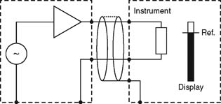
FIGURE 24.5 Unbalanced output; balanced input. A circuit is established. The display is OK. Note that the shielding is only connected to the receiving device.
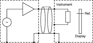
FIGURE 24.6 Unbalanced output; balanced input. A circuit has not been established. Hence nothing is displayed.
Balanced Out/Unbalanced In
With a balanced output connected to an unbalanced input, there are several possible errors that relate to how the balanced output is established. For electronic balancing, there are different possible circuits. The balancing may also be attained by using a transformer.
The main problem is the electronic balancing as shown in Figure 24.7. However, if a signal must go through to an unbalanced input, then the connection must be implemented as shown. The two frames must not be connected to each other.
In Figure 24.8, the connection goes totally wrong because the signal is grounded before it reaches the inverter.
Figure 24.9 shows a more common type of electronic balancing.
The following connection (Figure 24.10) is dangerous because there is a risk of only measuring half the signal, which will happen if one lead is not connected.
When an output is balanced by a transformer (Figure 24.11), the circuit is somewhat more manageable.

FIGURE 24.7 “Balanced” output; unbalanced input. The output is not correctly balanced, but the signal can be measured as long as the two chassis are not connected together.
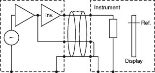
FIGURE 24.8 “Balanced” output; unbalanced input. No display! Because of the poor design of the output circuit, the signal is grounded due to connection to the chassis.
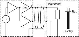
FIGURE 24.9 “Balanced” output; unbalanced input. The circuit is established, and the display is OK. However, the balancing is referenced to the chassis.
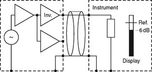
FIGURE 24.10 “Balanced” output; unbalanced input. Because the output is still referenced to the chassis, a signal arrives at the output, but only half of it (-6 dB)!
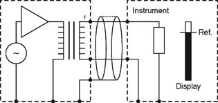
FIGURE 24.11 Balanced output; unbalanced input.
Balanced Out/Balanced In
When both the input and output are balanced, there is little that can go wrong. The circuit is created independent of whether the shielding is run through or not. It is then possible to consider possible ground and shielding strategies without thinking about the signal itself.
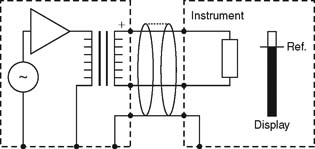
FIGURE 24.12 Balanced output; balanced input. A circuit is created regardless of whether the shielding is run through or not. The display is OK.
CONNECTIONS VIA A JACKFIELD (PATCHBAY)
If you are in possession of an installation with a jackfield (patchbay), it is always practical to have access to an instrument via that route. The main instrument can be run through the jackfield (patchbay) via so-called “half normalization” (i.e., the normal signal to the instrument is broken when a connection is inserted from the output one wishes to check).
LIVE SOUND
Regardless of whether you are producing live sound on a PA system or recording “live to tape” it is necessary to monitor the sound. This applies in particular to critical sources such as wireless microphones, or sources that are extremely variable in level.
It is not just the levels that have to be kept under control, but also the phase relationship between two outputs in a stereo setup; particularly if the signal will be played back in mono. A goniometer is almost a must-have in this situation.
THE INSTRUMENT AS A MEASUREMENT DEVICE
When you are in possession of a well-calibrated instrument, it is possible to use it as a measuring instrument. As a rule, an instrument that displays RMS can show the level of all signal voltages in the audio spectrum, particularly if it has an appropriately high input impedance (>10 kΩ).
One must know the significance of the scale, for example whether it is calibrated in dBu, such as with the Nordic scale on a PPM instrument. A level of 0 dBu corresponds to 0.775 volts. Many instruments have the option for amplifying the input signal, typically by 20 dB. 20 dB corresponds to an amplification of precisely 10 times.With the instrument’s logarithmic scale, it hence becomes possible to measure signals at less than 1/1000 of the instrument’s full scale. If the instrument ultimately will be used for larger signals, then an attenuator (of, for example, 20 or 40 dB) can be acquired. In this manner it also becomes possible to perform measurements in installations such as 100-volt loudspeaker systems.
DIGITAL CONNECTION
If you are in possession of a digital instrument, then there is the possibility of monitoring a number of functions at the same time. It is the instrument that the eye first falls on when the digital signals go haywire. A digital instrument is as a rule equipped with an AES/EBU or S/PDIF input. However, other interfaces are available as well.
The Meter is the Slave Device
When connecting it, the instrument will be designated as a slave. In other words, it will be clocked from the equipment that it is connected to. The AES/EBU interface is self-clocking, so if the meter is connected, then the instrument can follow along automatically.
It sounds simple, but it can be a problem if you have to use your mixer’s only digital output for the instrument, meaning that the output signal has to be analog. That of course is not good. Therefore, it can be quite practical to be in possession of a router or a switch, giving the option to make a connection as required. In many smaller studios, however, this is not the type of thing that money is used on first, so other solutions may have to be found.
One of the more economical possibilities is that you can place your meter on the output of the master machine that you are recording on, since it would be connected as a slave to the mixer. Another inexpensive variation could be to connect the meter to an S/PDIF coax output. It ought to be possible to get a digital meter to read the interface, even though the voltage is a little lower than AES/EBU. Certain information will be lost; however, you still have the information on level, on the sampling frequency, on the number of bits per sample, and on whether the units are locked to each other.
Sample Rate Converter
In everyday terms, the many sampling frequencies that are worked with in practice can certainly be a bit cumbersome. Because of this, a sample rate converter is frequently available. This allows all arbitrary digital signals to be converted to a common standard.
Where the digital instrument gets its signal from must be known. Some converters are not transparent and thus not all data come through, even if only the sampling frequency was changed.
Clock Distribution
The ideal for a setup with multiple digital devices connected to one another is to have a distributed central clock. It is not guaranteed that the level meter will have an input for an external clock; however, if the rest of the system runs on the distributed clock, then it can be significantly easier to connect the meter as required.
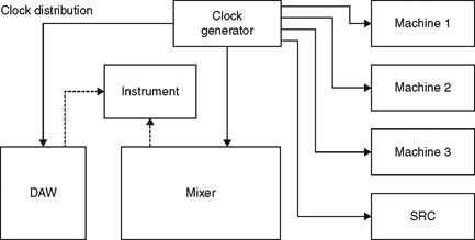
FIGURE 24.13 Setup of digital equipment with clock distribution. There is a clock generator that is shared by as many devices as possible, such as a mixer, digital audio workstation (DAW), and sample rate converter (SRC).
Networking
Analog audio needs a separate physical circuit for each channel. With digital audio, many channels can be carried in one circuit. The digital interface AES10 (MADI) can carry up to 64 channels. In digital audio networking it is possible not only to transport audio data but also to address the individual units attached to the network and to circulate lots of control data. A number of proprietary networks exist for different purposes, some of them based on Ethernet and the like. However, gradually general purpose open source networks like OSI, the Open System Interconnection model created by ISO, will find their way to the market.
When connecting to a network the meter, or the device including a meter, can be attached at any point in the chain.
LOUDSPEAKER/HEADPHONE MONITORING
Monitoring audio is of course not only a question of using visual displays. Listening is just as important – at least! So it is very practical to establish a relation between reading and the listening level. Further, it is important that the monitoring levels of speakers or headphones are well defined in order to mix for the right balance and keep levels from damaging hearing.
Regardless the type of signal distributed, analog or digital, a monitor controller with a built-in meter that is set to a reference listening level is an excellent device in all installations. Experience shows that less attention has to be paid to the visual meter when the engineer or editor is confident with the listening level.
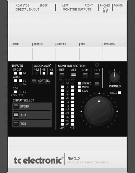
FIGURE 24.14 An example of a combined D-A converter, meter, and monitor control unit for loudspeakers and headphones. Digital inputs: S/PDIF, AES3, TOS and ADAT (including the ability to confirm if those inputs are synchronous or not). (TC Electronic BMC-2)