Nearly all electronic devices you can buy include one or more printed circuit boards (or PC boards). Luckily for the beginner, many kits are just right for learning how to use a PC board, like the through-hole kit learn-to-solder kit mentioned in Chapter 2.
There are two types of PC boards; through-hole and surface-mount. Components on a through-hole board have wire leads or terminals that extend through holes in the board, thus the name. Surface-mount boards, on the other hand, have no holes and the components are soldered directly to the copper cladding.
Note
Surface-mount technology (or SMT) components are much smaller than leaded components with wire leads (pronounced "leeds"), allowing the PC boards and the equipment that uses them to be much smaller than if through-hole boards are used. SMT components have either metal caps or very short leads designed to lie flat on the surface of the board. To the hobbyist, though, the components are much smaller than leaded parts and are harder to work with using regular soldering tools.
Note
Printed circuit board (PCB): A PCB is made from a core layer of insulating material such as fiberglass or plastic to which a thin sheet of copper (called cladding) has been attached on one or both sides. The desired pattern of conducting paths (called traces) is then printed on the copper. The PCB is then placed in a chemical solution that removes all of the copper except that covered by the printed pattern, leaving only the traces on the insulating core.
In this chapter, you'll learn how to work with each type of board by building a kit. You may choose to buy a different type of kit, but the techniques used are the same for all kits that use through-hole or surface-mount.
Before beginning to build either type of kit, you need to prepare your workspace. The most important thing for all phases and types of circuitbuilding is good lighting. You'll be peering at the tip of your soldering iron and trying to read tiny part markings. Working with poor lighting is no fun — and it leads to mistakes. A swing-arm desk lamp is a good temporary solution if you don't have a permanent workbench or table.
Note
Holding the PC board is also important. Trying to work on a board that slides around on the work surface can be frustrating — and can damage components or knock them out of alignment just as you're trying to solder them. A small machinist's vise will work for small boards. If you plan on building a lot of electronic stuff, you might want to invest in a Panavise (www.panavise.com).
Tip
As with any project, it's a good idea to keep your work area clean. Soon enough, you'll fill it with tools and bits of this and that. But when you're just learning, avoid distracting clutter in your workspace. If you are using a woodworking shop or maybe the kitchen table, buy a sheet of white poster board or cardboard to act as a work surface. You'll be able to see the parts much more clearly — and it will protect the underlying surface, too.
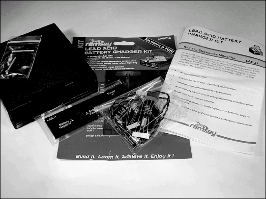
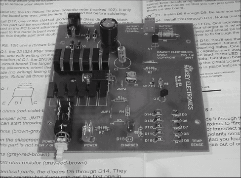
If you enter the phrase "electronic kits" into an Internet search engine, you'll discover dozens of companies that sell hobby- and professional-level kits. Your author needed a battery charger, and so selected the Ramsey Electronics (www.ramsey-electronics.com) LABC1C Lead-Acid Battery Charger shown in Figure 4-1. You don't have to build this particular kit — choose one that fills some need in your shop or around your home. If this is your first kit, select one that uses mostly discrete or individual parts (such as resistors, capacitors, transistors, and diodes) rather than pre-assembled modules or integrated circuits. These parts are easy to work with and solder; if you get familiar with them, then when you graduate to more complicated kits, you'll be ready.
Surface-mount PC boards are relatively new, especially to hobbyists, and require different techniques than the familiar through-hole boards. To teach circuitbuilders how to use surface-mount components and PC boards, several companies make training kits.
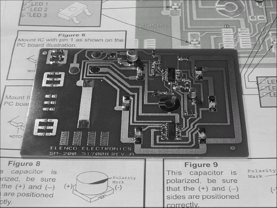
Building one of these kits usually creates a simple gadget to have fun with, as well as teaching you the basics of working with surface-mount components. One good kit is the SM-200K SMT Training Course kit from Elenco Electronics (www.elenco.com). The kit has a few practice components to get you started; when you're done, you'll have a silly "Decision Maker" gadget, as well! If you choose a different training kit, it will have similar steps and procedures.
Because the parts are so small, a head-mounted magnifier is very handy. These are available for a few dollars at fabric and craft stores. Single magnification of a few powers of magnification is fine — you do not need dual or high magnification.
Tip
You are also likely to drop a part or two. They bounce incredibly well! So well, in fact, that they are likely to wind up on the floor. A smooth, light-colored floor helps find the parts, but if that doesn't describe YOUR floor, spread out an old, light-colored sheet around the workplace so you can find that tiny part after it slips out of the tweezers.
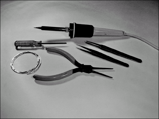
Figure 4-2 shows the basic tools that you'll need to work on SMT assemblies. The stainless-steel tweezers on the right are a good investment if you plan to build or repair electronics that use surface-mount technology.
The PC board for most hobby kits is at most a few inches on a side, and contains fewer than 100 components. The kit may come with an enclosure or it may just be a plain PC board that you can use by itself. In either case, the basic procedure shown in this task applies to both types of kits.
Before buying the kit, check to see if it requires a separate power supply, enclosure, or other materials that you have to provide.
The figures show how to construct most through-hold PC boards. The task will go well if you stay organized and follow the manufacturer's instructions carefully. Resist the temptation to do things out of order or skip steps. That's when mistakes are made — even if you have a little experience already!
As you build the kit, take notes (remember the notebook!) about construction and design details. You can apply these in your own designs later!
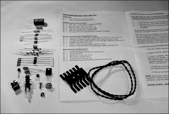
Open the kit and find the instructions and the parts list. Check off the parts and pieces against the parts list to be sure you have everything. It's also a good way to familiarize yourself with all the components.
Tip
Use the kit's instructions — especially the checklist — to help keep you from missing information or skipping steps by accident. Experienced circuitbuilders have learned (usually the hard way) that the manufacturer usually gives the instructions in a particular order for good reason!
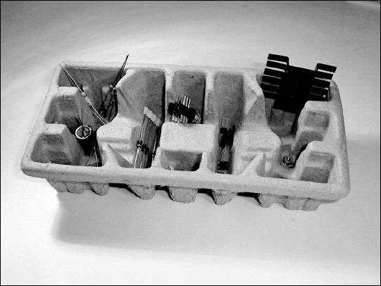
Sort the parts by type into a container that is divided into bins or sections. An inexpensive muffin or cupcake baking tray is popular in the workshop. Or look around your home — the cardboard bins in the figure were used as packing material! Egg cartons work well, too! You can also stick the leads of parts into a scrap piece of Styrofoam covered with aluminum foil (the foil eliminates static) to hold them while you work.
Read the assembly instructions thoroughly, even though you're anxious to get started. Build a picture in your mind of what you're going to do, and in what order. Look for sequences of steps that must be done in a specific order — and make note of warnings and cautions.
Tip
Look especially hard for errata in the manual or on slips of paper included with the parts. It's not uncommon for companies to have to substitute parts — or to discover and correct a layout or manual error. If you do find errata note them in the instruction manual or attach the errata sheet to the manual on the corresponding page so you don't forget about it.
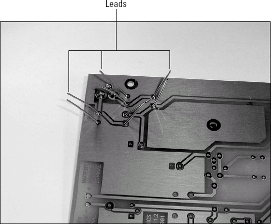
As you insert leaded parts (diodes, resistors, capacitors, inductors) into the holes, hold them to the PC board by bending the leads slightly apart. Bend them over at the PCB surface just enough so they stay in the holes and don't slide back out when you flip the board over to solder them. Don't bend the leads so much that they lie too close to the board (which would make them difficult to solder and trim).
Tip
If you are attaching an integrated circuit (IC) or an IC socket to the board, bend the leads at opposite corners of the rows of pins to hold the part to the board. Solder those leads first.
Solder the leads to the PC board pads. Don't use too much solder — you just want to cover the pad and flow solder onto the component lead. For components with short, thick leads that don't bend easily, melt a small ball of solder onto the iron tip, and then tack-solder one or two leads to hold the part. Then solder the rest of the leads, and go back to finish the job on the tack-soldered leads.
Note
Be sure components such as controls and switches are fully inserted when you're soldering them; mechanical alignment may be important for the panel or enclosure mounting holes.
Do a close visual inspection of solder joints before you move on to the next step. Look for the smooth shiny surface that shows the solder has flowed evenly over both the PC board pad and component lead before cooling and solidifying. Trim the leads just beyond where the solder joint wets the lead. Save the trimmed bits of wire for jumpers or other uses.

When you are installing polarized components such as capacitors and diodes, pay particular attention to polarity markings.
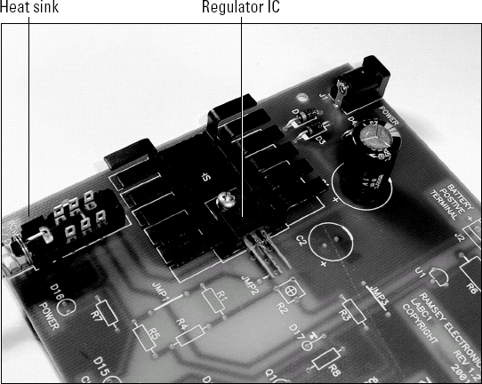
Some kits have mechanical assemblies such as the heat sink and regulator IC shown here. Make a dry run of any mechanical assemblies to be sure everything lines up where you expect. If it doesn't look right, don't complete the assembly until you've figured it out.
Note
Tighten up the mechanical assembly before soldering the leads. Soldering last minimizes mechanical stress on the solder joints.
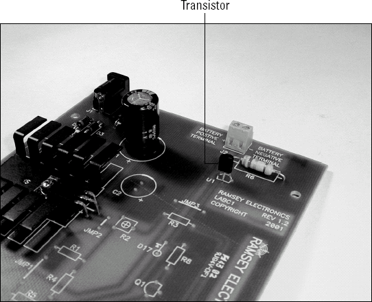
When installing transistors, don't force them down against the board. Spread their leads a little bit and insert until the leads feel tight in the holes.
Complete the checklist and give everything a close visual inspection — look for polarity, orientation, values, shorts, solder balls and solder bridges between pins or terminals. Brush the back side of the board with a stiff brush to clear off debris.
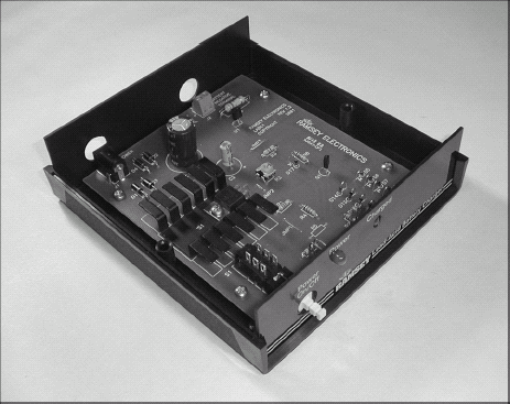
Install the board in the enclosure, if there is one. Perform the test and alignment procedures in the manufacturer's instructions. Congratulations!
You might have noticed that in the parts list step, both LEDs were the same color. The preceding step shows two different-color LEDs. What happened? Well, the author customized a little bit. If the LEDs are different colors (the one for power is green and so looks grayish in the figure and one that says full charge has been reached is red and appears dark), it's easier to look at the charger from across the room and check its status. Feel free to customize the kit (it's your kit, after all) as long as the changes don't affect its function. Substitute different color LEDs, change a connector, or even add a connector or switch. Don't be afraid to experiment!
If you have constructed a through-hole PC board, then you already know how to do most of the necessary steps to construct surface-mount boards. What will be new is the scale at which you work.
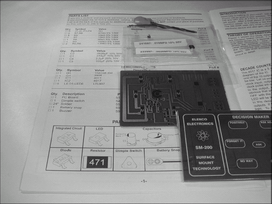
Open the kit and find the instructions and the parts list. Check off the parts and pieces against the parts list to be sure you received all of them. (Use a magnifying glass to read the tiny part markings.) SMT components are very small, so take your time and be careful. To pick components out of tape strips, pick the plastic film off with a sharp knife or tweezers.
Read through the instructions carefully. Take a few moments to familiarize with this type of component and the techniques for assembling a surface-mount PC board.
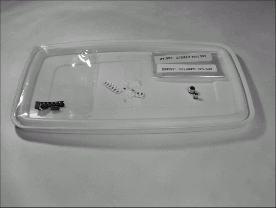
Instead of a set of bins for parts, a refrigerator storage container lid will work just as well. Keep the parts in bags by type if there are a lot of parts.
Warning
Keep any ICs in their shipping bags due to static sensitivity!
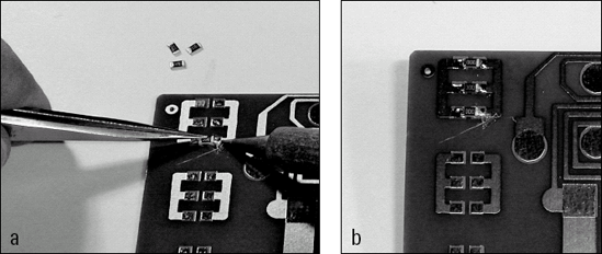
Most training kits have some practice components and pads on the PC board. This feature allows you to get used to the scale of soldering SMT parts before beginning the assembly for real. Don't proceed until you have learned the basic soldering steps. Your first couple of attempts might be pretty lame, but that happens to everybody.
You will soon develop your own style of SMT soldering. The author prefers to begin by lightly tinning the pad. Using tweezers, place the component on the tinned pads. Put a very small ball of solder on the tip of the iron. Hold the component against the board with the tip of the tweezers. ToU the iron to the component lead and pad simultaneously to flow the solder over both.
Start with the resistors and capacitors. Take your time and inspect each component with a magnifier after soldering. Look for a smooth fillet between each pad and the end cap of the component you're attaching.
Tip
As you work on the board, turn it to get the easiest access to the component. Soldering SMT parts is tough enough by hand without having to lean over the board awkwardly.
Warning
If you get tired, STOP! This is when you make mistakes, slip with the soldering iron, or knock parts on the floor. And you get frustrated. At least take a break, get a little fresh air, and be ready to have fun when you come back to the project. It's not a race!
For multilead packages (transistors, diodes, and ICs) tack-solder one lead first, then adjust the part's position until it's in exactly the right spot.
To solder the large capacitors, start by tinning the pads. Position the capacitor, then heat one pad while lightly pressing the capacitor down onto the board. Release the capacitor when the solder melts and the lead contacts the pad. (You'll be able to feel it.) Check alignment, then solder the other pad.
When you're soldering ICs, use the tack-solder technique in Step 7 to hold the IC on the board. Use the magnifier to make sure every lead is approximately centered on its pad. Hold the iron at the far end of the pad, toU it with the solder, and then bring the molten solder up to the IC lead by dragging the tip of the iron along the pad.