
In this chapter, we'll be looking at methods of getting your work out of ZBrush. We begin by looking at the ZMovie function, which allows you to create videos directly in ZBrush. These can be captured work sessions or turntable animations of your work. In the second portion of this chapter, we'll look at exporting images from ZBrush and compositing them in Photoshop to create dynamic "renders" of our characters.
ZBrush has the capability of recording your actions on screen as a movie. This recording can encompass just the document window or the entire screen, including menus. This is useful for training purposes or to showcase a technique. Recordings are stored in memory as a sequence of screenshots that may be saved as a ZBrush native format called a ZMV file or exported as a QuickTime video with any number of compression formats.
To record yourself in action, open the Movie menu from the top of the screen. Click the radial button

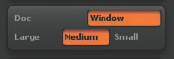
On the Movie menu, click the Window button (Figure 8.1). This will record the entire ZBrush window. In the next line, click the Medium button. This will record frames that are half the size of your current document. If you want a larger video output, increase your document size and select Large for 100% of the document size.
Click the Modifiers menu under Movie to unroll these options (Figure 8.2). The first slider is Frame Size, which specifies the scale factor for each frame. You set this by selecting Small, Medium, or Large in the previous step. By default, it is set to .5. If you set it to 1, the frames will capture at 100% of the document size. Leave this value at .5. Auto Zoom can remain at 0. Set Recording FPS to 20 and Playback FPS to 10. This slows down playback to a more natural speed. Leave the buttons Skip Menus, Antialiased Capture, and OnMouse on. If you want menus to be visible as you work (which may be desirable when you're demonstrating a technique), turn off Skip Menus—this will record menus as well as sculpting actions.
Unroll the Overlay Image and Title Image menus by clicking on their names (Figure 8.3). The Overlay Image is a logo that will be overlaid on the movie. The default is the ZBrush logo, but you can load any image from the Texture palette by clicking the ZLogo icon. To turn this off, set the Opacity slider to 0.
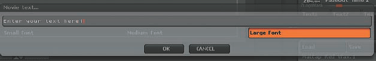
The Title Image menu defines the image and text that appears at the start and end of the video. You can load an image from the Texture palette by clicking on the Z icon. Enter text by clicking the Text1, Text2, or Text3 buttons. Clicking these buttons opens a text entry box (Figure 8.4) that allows you to specify font size and enter text in the field. To disable this, set the FadeIn and FadeOut sliders to 0.
When you're ready to record, click the Record button at the top of the screen. ZBrush will begin recording your actions. Perform a few strokes on the canvas; then when you are ready to end the recording, click the Pause button
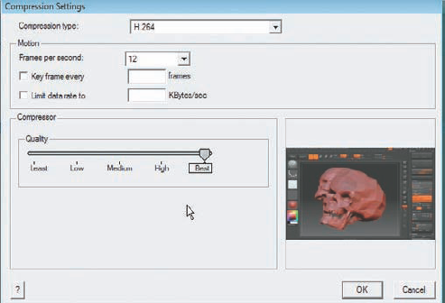
Once the ZMV is saved, you'll export a copy as a QuickTime file. To do so, click the Export button and specify a filename. Click SaveAs, and the QuickTime Compression Settings dialog box will appear (Figure 8.6). Select H.264 as the compressor, deselect Limit Data Rate To, and set the Quality slider to Best. Click OK, and your video will play as it exports. Do not press Esc or leave ZBrush during this process as it will cancel the export.


Note
For the best-quality results, I recommend exporting MPEG-4 with no compression from ZBrush and applying H.264 compression in QuickTime Pro. Set the compression to None and the Frames Per Second to the recording FPS set in the Movie menu. This should be the default value in the menu. Set Depth to Millions of Colors + and the Quality slider to Best. These settings will create a very large file, but you will have better results by compressing to H.264 in QuickTime Pro.
ZBrush comes with the capability of rendering high-quality rotations of your models. Turntables are a staple of most modeling reels and an ideal way to show off a sculpture in the round. While it is possible to do this in a third-party renderer, it is often faster to generate a rotation directly in ZBrush. You even have the option to add an overlay image of your name, logo or contact information. To create a rotation video, follow these steps:
Open the Movie menu from the top of the screen. Click the radial button to dock it on the side tray.
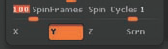
Under the Modifiers menu, set Recording FPS to 20 and Playback FPS to 20. At the bottom of the Modifiers menu is a SpinFrames slider. This determines the number of frames in a single rotation. To set this, determine how long you want a single rotation to be; in this example, use a 5-second rotation. If we are playing back at 20 frames per second, we need to multiply 20 by 5 to find the SpinFrames value. In this case, it is 100. Leave Spin Cycles set to 1 since a single rotation from ZBrush will loop when played back. There is no need to render more than one seamless rotation. You can set this value to −1 to reverse the direction of the rotation.
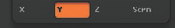
When you are ready to record, click the Turntable button at the top of the movie screen. The ZTool will rotate around its Y-axis. If the model seems to rotate in the wrong direction, change the Axis selection at the bottom of the Modifiers menu. The rotation video can be saved as a ZMV file or exported following the same steps as detailed in the previous section.
Note
Keep in mind that only one movie can be stored in memory at a time. If a movie is stored or loaded when you record, the new frames will be appended to the end of the last movie. To clear memory, click the Delete button under Movie to start a fresh recording.
While ZBrush has a powerful renderer in its own right, when you combine it with Photoshop you can get high-quality images, especially when combining different materials as render passes and compositing them in Photoshop. The following technique is based on a workflow shown to me by Scott Patton of Stan Winston Studio.
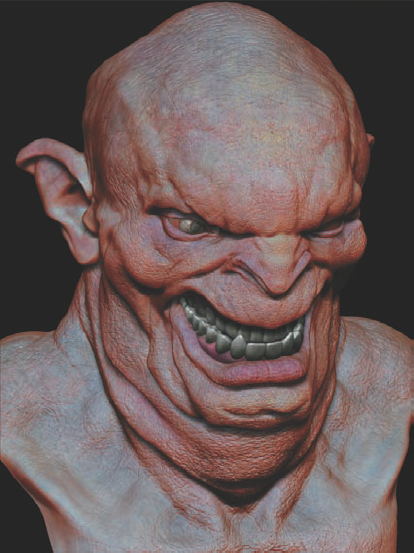
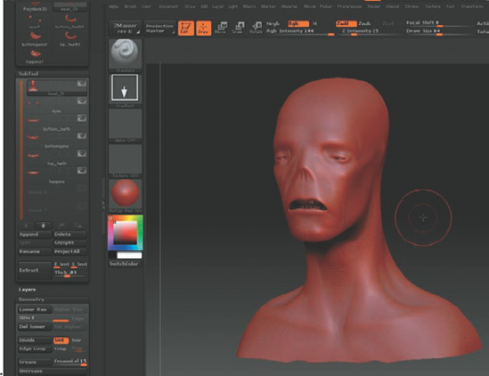
This technique is based on exporting a single render from ZBrush with various material types and then compositing them together in Photoshop using blending modes to create a deep, rich image. For this demonstration, let's use the Fat Beast character from Chapter 3. I have PolyPainted the face, eyes, and teeth and applied a MatCap skin shader to the skin and the basic material to the eyes and teeth.
Because this is a portrait image, we'll reconfigure the canvas from landscape to portrait:
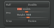
Open the Main document window and dock it to the side tray by clicking the radial button. Turn off the Pro button, which constrains proportions (Figure 8.7). Swap the Width and Height values so they read 720 wide by 960 high. Now click the Double button to double this document size to 1440 × 1920. ZBrush will notify you this is not an undoable operation. Click Yes.
If there were any active ZTools when you resized the canvas, they are now dropped to Pixols. Clear the canvas by pressing Ctrl+N. Let's now change the background from the default gradient to pure black. From the color picker, select black, and under Document, click the Back button. This assigns the currently selected color to the background. Turn Range and Center down to 0 (Figure 8.8).
Switch your active color swatch back to white and draw the character ZTool on the canvas. Turn on perspective with the controls found under the Draw (Figure 8.9). Click the Persp button to turn on perspective (or press the P hotkey) and adjust the focal length until the character looks good. Lower focal length settings will give more perspective distortion, resulting in a fisheye effect. Note that these values are contingent on the scale of the particular model and will not be consistent between ZTools (Figure 8.10).

In this section we'll create several versions of our character with different material settings. These various renders will be loaded into Photoshop and composited together:
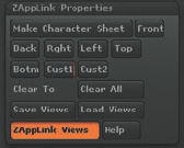
Since it is important to maintain the exact same positioning between each render pass, now is a good time to store the character's position on the canvas. You could drop it to the canvas and create Pixols, but this would prevent you from making separate subtool passes unless you dropped each to a different layer. Storing the character's position is the easiest way to ensure you can return to the same position if you accidentally move the character. Make sure ZAppLink is installed, and under the Document menu, open ZAppLink Properties (Figure 8.11). Click the Cust1 button to store the character position in the Custom slot. Save your views by clicking the Save Views button. For more information on using ZAppLink, see Chapter 5.
The first render pass we'll export is the standard skin shader. Click the AAHalf button on the right side of the screen

The next pass will involve flat color—just the color as painted on the surface with no shading information. From the Material palette, select Flat Color

Note
If you have filled an object with a material, the only way to change materials is to fill it with another. The default behavior of the ZTool displaying the currently selected material is overwritten. To revert back to this behavior, fill the object with the Flat Color material. From then on, whatever material is selected will be the one displaying on the character.
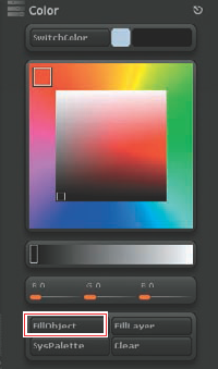
To fill the head with this material, select the Standard brush and turn on M at the top of the screen. Make sure RGB is off (Figure 8.12). Then open the main Color menu and click the FillObject button (Figure 8.13). Repeat this fill for each subtool and export the document as
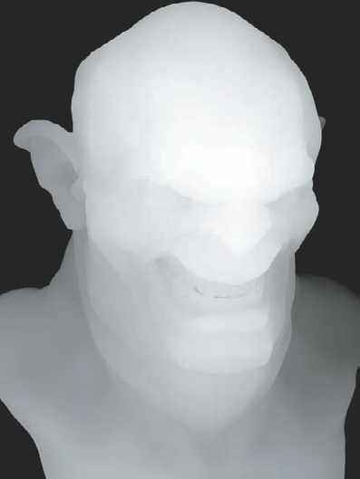
flatcolor.psd(Figure 8.14).The next render is a shadow pass. This will assist us in faking an Ambient Occlusion style render. Turn off Colorize under Tool → Texture and fill the object with the Fast Shader. Open the Material modifiers and turn Ambient and Diffuse up to their maximum settings (Figure 8.15).
We also want to create a cavity map to allow us to isolate the sculpted details in Photoshop. To generate a cavity map, step down to the lowest subdivision level. Choose Tool → Texture and turn on Enable UV; then click the AUVTiles button to generate UV coordinates (Figure 8.16).
Step back up to the second-to-highest subdivision level. You want to capture just the fine details in the cavity map, so you won't generate it from the lowest level. Open ZMapper by clicking the ZMapper button on the upper left of the screen. Open the Normal & Cavity Map tab at the bottom of the screen and raise the Cavity Intensity slider to about halfway. You may also decide to raise Cavity Blur (Figure 8.17).
Click Create CavityMap. When the map completes, press Esc to exit ZMapper and export a document image of the cavity map on the character (Figure 8.18). This image will work best if you change your material to Flat Color. For a more in-depth look at ZMapper, see Chapter 10.
The final passes are utility renders for depth and masking. The first pass will be a depth grab of the canvas. Recall from Chapter 4 that you can grab the depth information of the ZBrush canvas as an alpha. We'll do this now and use the resulting image as a mask in Photoshop for various effects, including simulating depth of field. Go to the main Alpha menu and click the GrabDoc button. This will grab a depth sample of the canvas with white values closest to the viewer and black farthest away.
A final version of this appears in Figure 8.19. This is sometimes called a ZDepth image. Be aware that the image will use the actual document resolution although you are displaying the document in antialiased half mode. When you use this image in Photoshop, you'll have to manually resize it by half.


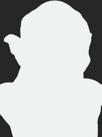
The remaining images are to be used for knockout masks if you decide to change the background, or if you decide to isolate the eyes or mouth subtools from the head. To create these masks, turn on MRGB at the top of the screen. This will fill the subtool with color as well as material. Select the color white and fill each subtool with white and Flat Color. Figure 8.20 illustrates this effect. Be aware that doing this will delete any PolyPainting you have applied to the surface!
Note
Here's an alternative approach: if you drop your character to the canvas by pressing the T key to leave Edit mode and then invoke ZAppLink by pressing Ctrl+Shift+S, ZBrush will send a document to Photoshop that contains a shading layer, a Flat Color layer, and a mask.
Click the SysPalette button under the main Color menu and select green RGB value 0, 255, 0. Under the Document menu click the Back button to fill the background with chroma green.
Now select each subtool with the exception of the head (which will remain white). With green selected, you'll fill the eyes and mouth with the color green and the Flat Color material. This will make isolating these subtools much easier in Photoshop (Figure 8.21). Save this document as knockout.psd.
Note
At this stage, you can save a ZBrush document of this character for future use, in case you decide to make changes at some point using the ZBrush 2.5D tools. These tools are covered in depth on the Chapter 1 bonus materials on the DVD. To save a ZBrush document, go to the main Document menu and click SaveAs. Save your document as a ZBR file. This is only a Pixol image and not a 3D model.
This concludes the process of creating our render passes. We are now ready to go to Photoshop and put everything together.

In the following sections, we'll take the render passes from ZBrush and composite them in separate layers. Using various blending modes, we'll create a rich and dynamic image much faster than we could by rendering in third-party software.
Note
I have included the ZTool, skin material, and render passes on the DVD if you would like to follow along with this exercise. I encourage you to experiment with different settings and see what kind of results they yield.
To begin, load the
sss.psdimage into Photoshop. This is the image of the character with the Skin shader applied to the head and Basic material applied to the teeth and eyes. This will serve as our base (Figure 8.22).Now load the
ambient.psdfile. This is the black-and-white image with only shadow information. Select the entire image and copy it.Switch back to
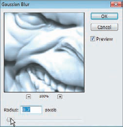
sss.psdand paste the image from ambient.psd intoSSS.psd.Ambient.psdwill now be a new layer insss.psd; name this layer ambient and set the blending mode to Multiply. Lower the opacity to 44%. Apply a slight blur to this shadow layer by selecting Filter → Blur → Gaussian Blur. From the pop-up menu set the Radius to 0.7 (Figure 8.23). This layer will accentuate the shadows.Open
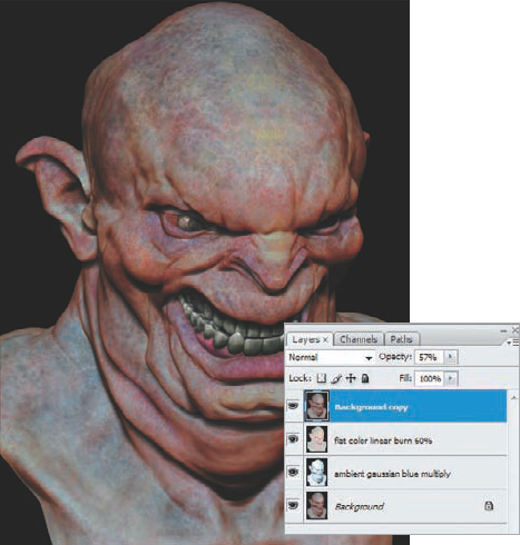
flatcolor.psd. Select the entire image, then copy and paste it into thesss.psdfile. It will come in as a new layer (Figure 8.24). Set the layer blending mode for the flat color layer to Linear Burn and lower the Opacity setting to 60%.The flat color layer has punched up the saturation and depth of the skin, but now we need something to mute this color a bit to make it feel more like translucent skin. Select the background layer (the original
sss.psdfile). Press Ctrl+J to copy the background as a new layer. Click and drag this layer to the top of the stack, and dial the Opacity setting down to 57%. The document now looks like Figure 8.25.


We'll now load the masking image we made earlier:
Load
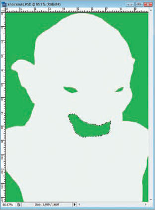
knockouts.psd. Copy and paste it into the working document. We'll use this document to create some saved selections. Using the Magic Wand tool [i0805.tif], select the green swatch for the mouth (Figure 8.26).With the marching ants active around this selection, choose Select → Save Selection and name this selection Mouth. Repeat this process, saving a selection for each eye and the background.
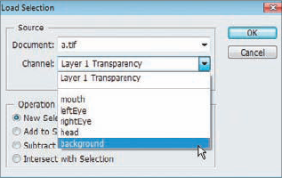
Now when you choose Select → Load Selection, you will find each of these saved selections ready for you (Figure 8.27). You can now delete the
knockout.psdlayer as we won't need it anymore.
We'll use the saved selection for the left eye to create a dead-eye effect:
Choose Select → Load Selection, select LeftEye from the dropdown menu, and click OK.
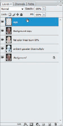
The left eye will now be surrounded by the Photoshop marching ants selection marquee. Make sure the background layer is selected and press Ctrl+J to copy the eye as a new layer. Name this new layer eye and move it to the top of the layer stack (Figure 8.28).
Select the eye layer and choose Filters → Artistic → Plastic Wrap. Adjust the sliders until you get a suitable dead-eye effect. Click OK when complete.
Now open the
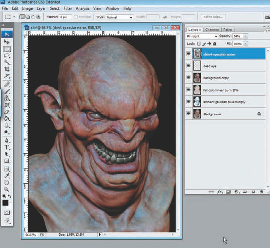
skinspec.psdfile. This is the plain Skin shader with no PolyPainting that we saved earlier. Copy and paste it into the document. Set the blending mode to Pin Light and the Opacity setting to 54%. It is also a good idea to add some noise to this layer by choosing Filter → Noise → Add Noise and setting Radius to 2.45 and Distribution to Uniform. This adds a shine to the surface of the skin (Figure 8.29).
At this stage, we want to accentuate the skin details. To do this, we'll use the cavity map pass we rendered earlier.
Open the cavity.psd file and paste it into the active document. Set the blending mode to Multiply and Opacity to 37%. It is also a good idea to add a touch of Gaussian Blur to this layer. Keep the radius near 0.5. At this point the composite character looks like Figure 8.30.

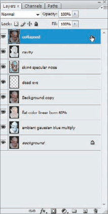
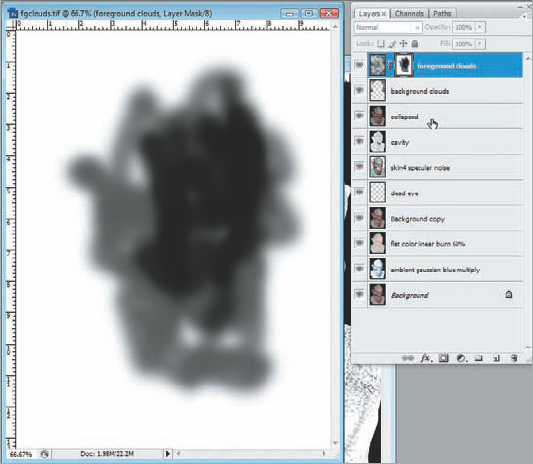
Now all that remains is a bit of lighting, environment, and postprocessing. We'll create a new layer that consists of all the active layers collapsed into one. This will allow us to keep our previous layers and work on a new collapsed layer. Press Ctrl+Alt+Shift+E to create this new collapsed layer, and name it collapsed (Figure 8.31).
Let's add a cloud layer for the background as well as a depth-of-field effect to add to the realism of the image.
Load the background selection by choosing Select → Load Selection and selecting Background. Create a new layer and choose Filter → Render → Clouds. Turn the opacity down to 37%. Because the background selection was loaded, the figure will be matted out of the cloud background (Figure 8.32).
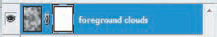
Create a new layer and name it foreground clouds. Clear any previous selections that may be active. Create a new cloud effect by clicking Filter → Render → Clouds.
Turn the opacity of this layer down to 25%. We'll want to selectively erase some of the clouds covering the face so they serve as more of a framing element than obscuring the figure.
In Photoshop, it is always best to use masks to remove part of an image instead of erasing because the Eraser tool destroys pixels while a mask only hides then from view. You can always alter the mask if you decide you need more clouds in an area.
To create a mask, make sure the foreground clouds layer is selected and choose Layer → Layer Mask → Reveal All. This will create a layer mask attached to the foreground clouds layer.
The mask will appear as a white box next to the foreground clouds layer. In Photoshop, white appears to be transparent and black is opaque in a mask. Select the Paintbrush tool and the color black. Make sure the mask is selected by clicking it once in the Layer menu. A small rectangle appears around the layer mask when it is active. Start painting on the image, and you will notice it makes the cloud layer disappear while the mask begins to show your black strokes. To restore the cloud area, just switch to white. If you want to view just your mask, Alt-click the mask icon in the Layer menu and your mask will become visible (Figure 8.33); to restore the regular document view, Alt-click the layer mask icon again.
Paint out the clouds around the face and eyes as this is the center of interest. You can let them remain around the shoulders and ears (Figure 8.34).


Now we'll add a depth-of-field effect to the image using the depth.psd image that we exported from ZBrush:
We need to resize the current file to the other document's resolution. Choose Image → Image Size and set the resolution to 720x960 (Figure 8.35). Remember that we were exporting documents at half size, but the Alpha menu exported this depth grab at full resolution.
Invert the depth grab by pressing Ctrl+I, then select all and copy the image to the clipboard. Select the collapsed layer and create a layer mask by clicking Layer → Layer Mask → Reveal All. Select the layer mask by Alt-clicking the layer mask icon and paste the depth grab into the layer mask (Figure 8.36).
We'll use this depth grab to calculate depth of field. Choose Filter → Blur → Lens Blur to open the setting box shown in Figure 8.37. Set the source to Layer Mask, Focal Distance to 15, and Noise to 4. Noise will help counteract the perfect look of a 3D render and add some imperfections to the scene.
Click OK and the filter will apply to the image. Now click the layer mask in the Layer menu and click the trashcan button


The final touch is a lighting effect to draw attention to the dead eye, the focal point of the image.
With the collapsed layer selected, choose Filter → Render → Lighting Effects (Figure 8.38).
Select Spot as the light type and place it with the Circular Light modifier. When you are satisfied with the light effect, click OK. Your final image should appear as Figure 8.39.
You can make further changes by handpainting details in Photoshop. Use the Dodge and Burn tools to accentuate shadows and highlights. You can even use the Liquefy tool to adjust the overall shape of the head. The possibilities are endless, and with this technique you can quickly create powerful renders with just ZBrush and Photoshop.


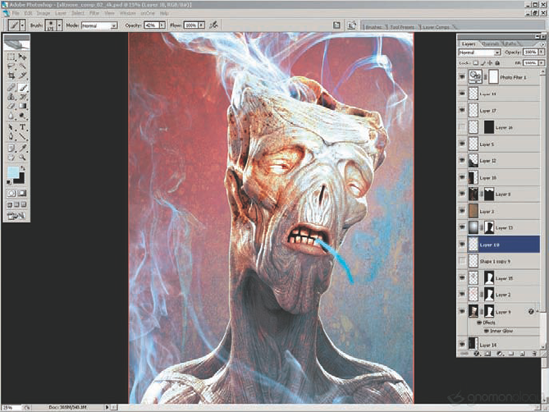
This section was contributed by featured artist Alex Alvarez.
Although Fume could have been created entirely in 3D, it would have taken much longer to produce. The workflow I'll describe keeps things quick and fun.
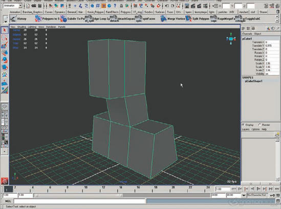
Between work and family, it can be hard to make the time to focus on a purely personal project, but I eventually decided to make some sort of humanoid portrait. I chose to box model a simple form in Maya (Figure 8.40). The problem with an older base mesh is that it will inevitably guide what I do, and for this project I wanted to be free.
I exported the simple box model to ZBrush, subdivided it a few times, and used the ClayTubes brush to block out the forms. I then retopologized the sculpt (Figure 8.41). Although I could have worked more on the sculpt before retopologizing, I wanted to be able to jump to Maya with a new generic humanoid base mesh. This would allow me to add thickness to the eyelids, a mouth interior, and position the necessary subtools (eyes, teeth, gums). In addition, the mesh would be generic enough at this point that I could use it as a start point for future characters in this style.
As should be the rule with any organized topology, I created the new base mesh in ZBrush following the anatomical forms defined in my initial rough sculpt. This can be tedious in Maya, but in ZBrush I actually enjoy it. Retopologizing a mesh is like solving a puzzle. It is, however, still time-consuming; this mesh probably took a couple hours. Once the topology was complete, I made the adaptive skin and exported it to Maya.
In Maya I edited the base mesh, first by adding thickness to the eyelids and positioning the eyeballs. I then worked on the inside of the mouth, extruding edges inward to create a mouth cavity that extends down the throat a little. Even though the character in the final image has his mouth closed, at this point I didn't know where things were going and wanted to have that as an option. For the gums and teeth, I was tempted to create new ones (he would perhaps have a nonhuman number of teeth), but I got lazy and just grabbed something I already had and positioned/deformed the teeth to match the proportions of his mouth interior.
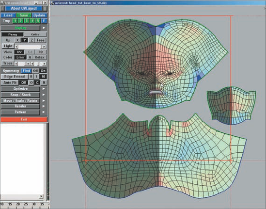
The final step before heading back to ZBrush was to lay out the UVs for the head using headus UVLayout (Figure 8.42). I chose to separate the head into three shells, for the head, neck, and mouth interior. The quality of the flattening in UVLayout is directly related to where you choose to cut things, and this worked pretty well. I then organized the UV shells in Maya for all of the objects (head, teeth, etc.), making sure that each mesh did not contain any overlapping UVs. I then exported each element as an OBJ.
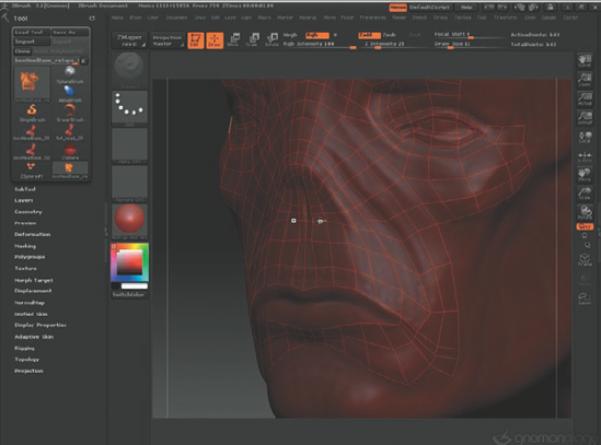
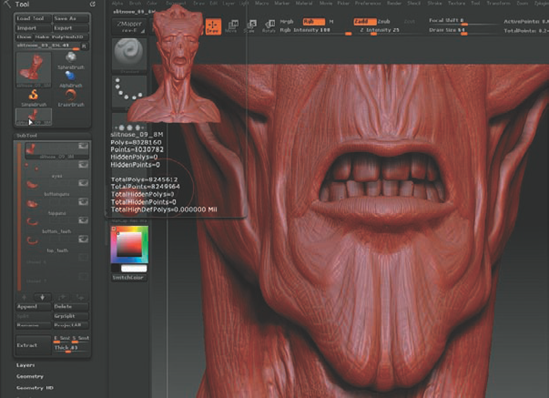
Back in ZBrush, I imported the UV'd meshes and organized them into a single ZTool with six subtools: head, eyes, upper teeth, upper gums, lower teeth, lower gums (Figure 8.43). I next began the fun process of sculpting and designing. The primary tools I used were ClayTubes, Rake, Standard, and Move. This was a freeform sculpting session where I just allowed myself to have fun and see where I ended up (Figure 8.44). I did jump to Maya a couple times with a high-res export of the head model just to test lighting and composition, in order to help determine where I should focus my time in ZBrush; there is little point in sculpting on the back of the head for a front-view portrait. For fun, however, I did end up spending some time on all sides of the sculpt, which also helped me "find" the character.
Once I decided that the sculpt was pretty much done in ZBrush, I exported the subtools that had been modified back to Maya, with corresponding normal maps. For a still image, I do not bother with displacement maps, as I don't mind having a heavy mesh in Maya. The sDiv level that I send to Maya as an OBJ is determined by choosing the level that defines the silhouette of the character accurately. For Fume, the sDiv level ended up around 250,000 polys.
Back in Maya, I began by setting up Blinn shaders for each object and assigning the normal maps. I could share a single shader for both sets of teeth by moving the UV shells for the bottom teeth one unit to the right in U space (Figure 8.45). The top teeth UV shells were in 0–1 and the bottom were in 1–2. On the shader, the top teeth normal map was mapped to the bump channel, and the bottom teeth map was mapped to the Default Color attribute on the top teeth map. Then I unchecked Wrap U + V on the 2D placement nodes for both maps. Finally, I set Translate U on the bottom teeth 2D placement node to 1.

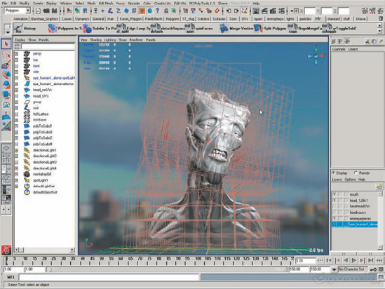
I had a basic Blinn shader on everything, and I began to do some composition and lighting experiments with mental ray. I started with some HDRi tests, trying out different HDR lightmaps (Figure 8.46). While these tend to look interesting, I never rely solely on HDR simply because I prefer to design my own lighting. For my final light rig, I created four directional lights and one spotlight. I liked the HDR tests that had strong rim lighting, so three of my directional lights were back lights. My spotlight was illuminating just the face from a high frontal ~TQF with a small cone angle and high penumbra (edge softness). All of the lights featured raytraced shadows. During the lighting process, I also chose to create a quick skeleton and lattice rig for posing (Figure 8.47). I simply selected the objects, put them in a lattice, and skinned the lattice to a skeleton. This is a very quick solution for posing that takes only a few minutes.

As I approached a light rig that I considered final, I decided to incorporate a cavity map into my Blinn shader for the head. I jumped back to ZBrush and, using the Cavity Mask option, filled the object with black. I then transferred the PolyPainted color to a texture that could be exported. In Maya, I assigned the cavity map to the Blinn shader color, and then adjusted the color balance to reduce the contrast in the image and make the effect subtler. So in the end, my final lighting/shader setup for Fume in Maya was rather simple: Blinn shaders, normal maps, one color map, and five lights.
Once I got to a point that I liked the lighting, composition, and pose of the character in Maya, I rendered a high-res and smoothly antialiased image with an alpha channel that I could bring into Photoshop.
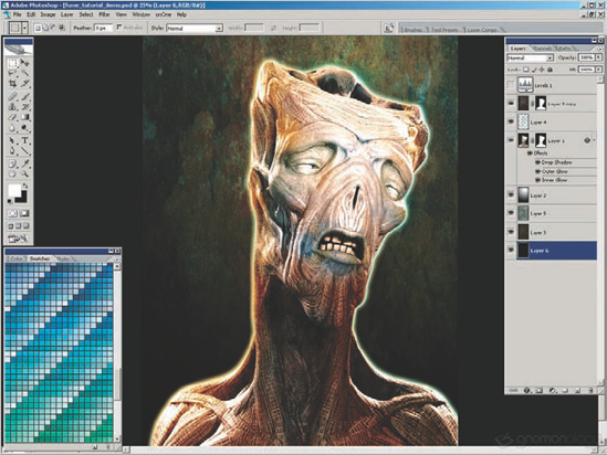
In Photoshop, I experimented with a lot of different directions (Figure 8.48). I imported textures and tried out blending modes. I created gradient overlays to adjust lighting. I painted on layers with different colors and blending modes to colorize the render. Basically I was texturing the image in Photoshop instead of in 3D. This is a far quicker process and allows for many iterations to be produced in a short time. If you want to texture your character in 3D, you can use these 2D experiments as a guide.
After perhaps an hour of experiment, the idea for smoke and a cigarette emerged. I painted some smoke coming out of the top of his head and liked the idea. But to develop that idea, I need to either paint the smoke by hand, create it in 3D using dynamics, or use photos. I chose photography, the quickest option that would produce good results.
Back in Photoshop, I experimented with some of the photos, compositing them using the Screen blending mode. Because they were shot with a black background, simply adjusting Levels gave me a perfect comp. I integrated seven smoke images by using the Liquify and Warp tools (Figure 8.49).
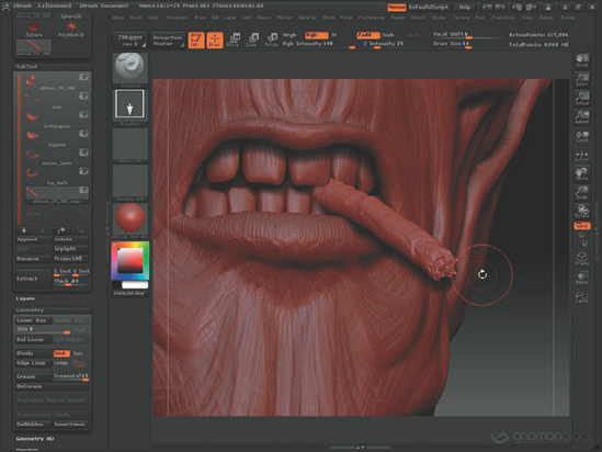
With the smoke mostly worked out, it was time to create the cigarette. In Maya I created a cube, extruded a face a few times to make it cylindrical, and positioned it in the mouth where I wanted it in relation to the teeth. I knew that I wanted my character to be biting the cigarette. I then flattened the UVs in Maya and sent the OBJ to ZBrush for detailing. I smoothed it a few times and then primarily used the Standard brush (drag rectangle) with various standard ZBrush alphas.
As I imported the cigarette from Maya, it was intersecting the teeth, so I added depressions to make it look like the teeth were clamping down on it (Figure 8.50). I also used the Move tool to give the cigarette a bit of sag. Once the image was complete in ZBrush, I sent an OBJ and normal map to Maya for final rendering. In Maya, I created a Blinn shader with no reflectivity and a broad and minimal specularity. I did not create any 3D textures for the cigarette; as with the head, I would do that later in 2D. I chose to render the cigarette separately from the head, so I created two new 4096x4096 renders. One render was of the head with the cast shadow of the cigarette but no cigarette (I achieved this by turning off Primary Visibility for the cigarette geometry). For the render of the cigarette, I set all of the shaders, except for the cigarette shader, to Black Hole matte opacity. This caused all objects to render as black in both the RGB and the alpha. I then took these two renders and integrated them into my multilayered Photoshop comp.
I created a couple overlay layers above the image to colorize the cigarette, adding a brown filter, the burned tip, and a brand label (Zufuhr brand smokes) using the Text tool and a little warping, and finally added more smoke coming off the cigarette.
With all of the elements in place, I felt my Photoshop composite needed some final color correction and contrast adjustments to make it appear stronger and less washed out (Figure 8.51). The main changes I made at this stage were creating a Levels adjustment layer for the entire composite and increasing the saturation of the background.
