Now that the sculpting phase is complete, you may decide your model needs to become part of an animation pipeline for fIlm or video games. The base mesh you created in Chapter 1 is ideal for the process of sculpting the character, but it is not suited for rigging and texture mapping. In this chapter, you will learn how to rebuild the underlying topology to be suitable for such applications. Remeshing, also known as retopology, is the process of creating a new underlying base topology for a model while retaining the high-resolution detail of the original sculpture. This can involve creating a new ZTool that retains the multiple levels of subdivision; or it can involve simply creating a "cage mesh" that contains the volume of your high-resolution image and then uses Create a Normal Map or another map-generating method to create a normal or displacement map that captures the high-resolution details of the sculpture and is ready to apply to the low-resolution model. The latter approach is often used in game pipelines for normal mapping.


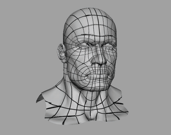
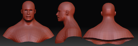
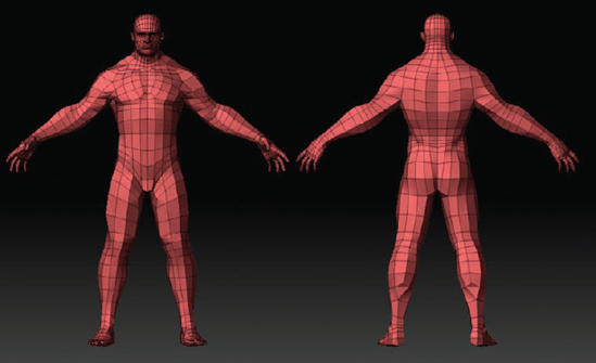
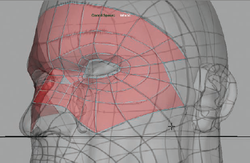
Figure 8.1 shows the hero fIgure being remeshed.
Remeshing refers to the process of rebuilding the underlying base mesh of a sculpture while retaining the higher subdivision's details. In theory, you could begin with an ordered animation-ready mesh in ZBrush and avoid remeshing entirely. Many people prefer to work this way, but I find it has drawbacks. Often a model with topology laid out for specific forms can be less malleable in ZBrush, and you may actually find yourself fighting against the existing edge layout to create the forms you want. By starting with a simple mesh, you can get the maximum number of subdivision levels and total freedom to sculpt the forms you want. Once the design/sculpting phase of the figure is complete, you can remesh the model into an animation-ready topology that lends itself to rigging; such a mesh also makes it easier to create effcient texture coordinates to facilitate creating texture maps. This allows the artist to tailor the edge flow to the specifc shapes that were defined in the sculpting phase instead of trying to sculpt shapes into an existing topology.
Problems can manifest in areas like the head or shoulder region, or anywhere else major forms have been looped into the mesh. Figure 8.2 shows the base mesh of the hero's legs compared to the high-resolution sculpt. Notice how much I was able to sculpt from very little underlying topology. This was a benefit of using a very simple sculpt to start.
Often in interactive applications such as video games, the topology will have to define not only the muscle forms of the character, but also costume elements. This allows the normal mapping to perform more effciently, because there will be a polygon edge where a hard edge should appear on the model. The result will be that the figure will look correct from all angles. These topology edges also help define the silhouette of the figure, which is very important in game models. Since you are limited to your poly count, making the best use of your edges to define the profiles is imperative. To do that, you need to understand and apply topology theory.

The model you built in Chapter 1 was specifically designed to facilitate ease of sculpting. The underlying edges were placed evenly down the model to make for a very simple block man. This kind of model allows for the most flexibility when sculpting in ZBrush. When you want to texture and animate a model, you will do better with a more elaborate underlying topology. By having edges that conform to the areas of high deformation, a setup artist can rig the character so it deforms realistically when animated. Figure 8.3 shows the character's knee bending in the sculpt mesh compared to the remesh. Notice how the edge loops help you maintain the volume as the limb deforms.

These same loops are helpful to a texture artist who needs to isolate parts of the body and generate texture coordinates (UVs). The process of laying out topology can be involved and technical, and it is often best approached after the sculpting phase. This allows design aspects to be worked out ahead of time without the limitations that may be introduced by topology.
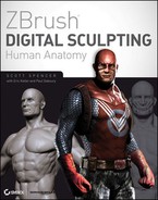
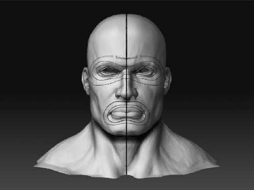
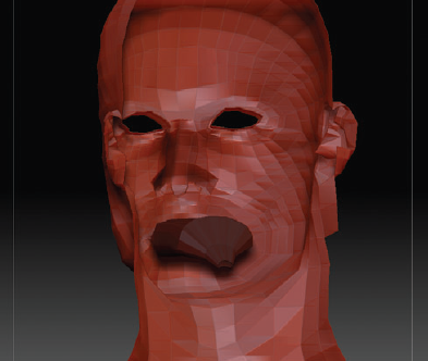
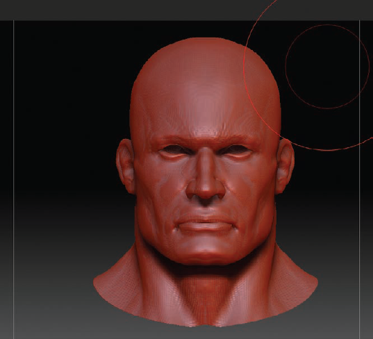
Figure 8.4 shows the original topology of our figure's head compared to the remeshed animation model. Both retain the same high-resolution details, but the remeshed head will be far more suitable to an animation pipeline because of the logical fow of faces around the eyes and mouth. For an exhaustive look at edge flow for animation, I highly recommend Jason Osipa's book Stop Staring: Facial Modeling and Animation Done Right (Sybex, second edition: 2007).
Figure 8.5 shows how a properly edge-looped face can assist the modeler in sculpting realistic blend shape targets. Notice how the edge loops allow you to pull a realistic nasola-bial fold from the existing geometry at the lowest subdivision level.
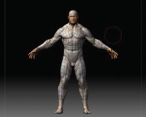
In addition to its benefits for animation, an ordered mesh also accommodates the process of texture mapping. By having the limbs looped in a sensible manner, the artist can cut UV edges and unwrap the model more effciently. Figure 8.6, for example, shows how an ordered mesh of a character from the waist down can be efficiently peeled open for UV mapping.

Figure 8.4. The model's head: (a) original topology, (b) remeshed. Note the flow of loops around the eyes and mouth.

These benefits are difficult to appreciate unless you have experienced the challenges of trying to UV and animate a mesh that was not designed for such a purpose. After even one attempt at this, the benefits of an ordered mesh will become clear. By taking a few hours to create a standard topology for your figure, you will open up many more applications for the model as well as have far fewer problems down the pipeline.
In a professional environment, an ordered mesh is mandatory. In both film and games, the pipeline depends on having a model that is not only a good sculpture, but is properly UVed and usable for the setup artists to rig and bind. Even if you don't plan to animate the model, a standard topology will allow you to more easily pose the mesh in ZBrush as well as have more freedom and flexibility when generating UVs and painting textures.
In this chapter, you will learn about two methods of remeshing the sculpture into an animation-ready topology. You will first examine how to use ZBrush's built-in topology tools. This is a powerful set of tools you can use to quickly generate models directly inside ZBrush. Later in this chapter, you will look at an alternate approach to generating an animation mesh, a Maya plug-in by Digital Raster called NEX.
In this section, you will work with the ZBrush topology tools, which are located under the Tool menu when you are working with ZSpheres. My special thanks to this book's technical editor, Paul Gaboury from Pixologic, who cowrote this section and created the example demonstrating the strengths of the ZBrush topology tools.
Laying out topology for an animation mesh can be very daunting. ZBrush simplifies the process and makes creating new topology easier than ever before.
Before constructing your topology with the retopology tools, you will lay out your topology by polypainting your topology lines right onto the mesh. Polypainting is the process of painting RGB color directly onto your mesh in ZBrush. This topology map will help guide you as you start laying in edges and will generally help keep the process simple and easy to complete.
Load the hero ZTool into ZBrush. Draw it on the canvas, and enter edit mode with the T hotkey.
You will need to fill the character with the color white as a base on which to paint. Make sure MRGB is on at the top of the screen, white is the selected color, and the fast shader is the active material. Select Color → Fill Object to food the mesh with white.
Since you will be using polypainting to color the mesh, you need to make sure there are enough subdivisions to display the lines crisply. Divide your mesh up enough to capture the polypaint; in most cases, a few million polygons will be enough. When complete, your mesh should look like Figure 8.7.
Select the Standard brush with a Freehand Stroke setting. To help draw smoother lines as you draw, turn on Lazy Mouse in the Stroke menu. Set LazyRadius to 10.

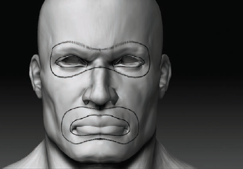
You will start by remeshing the head. This is the focal point of the character, and it contains many of the most specific loops for animation. Those are the loops around the mouth and eyes that allow for natural facial expressions. Notice how these loops mirror the flow of the underlying facial anatomy, discussed in Chapter 3. When you are building a mesh for animation, always try to run the major loops of edges so they encircle the areas of greatest muscular deformation on the face. These take the shape of a bandit's mask around the eyes and what I call a clown mouth around the lips. You will see bothformations shortly.
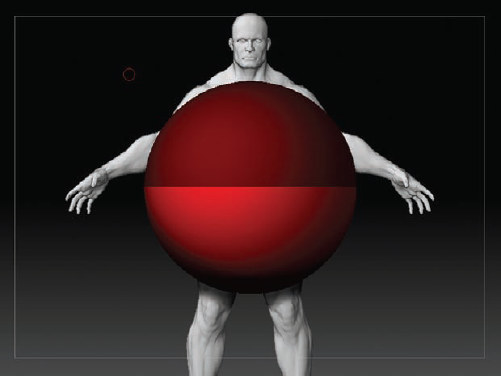
Begin by narrowing your work area by holding Shift+Ctrl while you drag out your selection area, which will be a green square. Everything that is in the green square will be selected, and the rest of the mesh will be hidden. Select just the head, as shown in Figure 8.8.
When creating an animation mesh, edge loops control the expressions that you will apply to a mesh. The first edge loops on a face are crucial for animation, as shown in Figure 8.9. They will establish the base for all expressions. Here you can see the bandit mask and clown mouth. Draw the loops around the eyes and mouth. To create a cen-terline, turn on the X symmetry by clicking X. You can also find this in the Transform palette. You will see two red dots on either side of your mesh. Drag until both dots touch, and hold the Shift key to draw a straight line down the middle of your mesh.
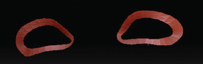
You will want to add loops inside the first major edge loops to further define the eyes and mouth. Notice in Figure 8.10 how the last two loops inside the eye don't loop all the way around both eyes, but rather form the "eyeholes" in the bandit mask.
Continue to draw in your edge loops on the face, as shown in Figure 8.11, in order to create topology to capture the various expressions of the human face.
Finish off the topology of the head, as shown in Figure 8.12. Maintain the edge loops of the eyes and mouth. Maintain the basic shape of the ears to capture the detail for the projection that will be applied to the new topology.


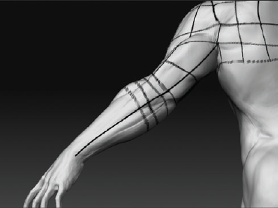
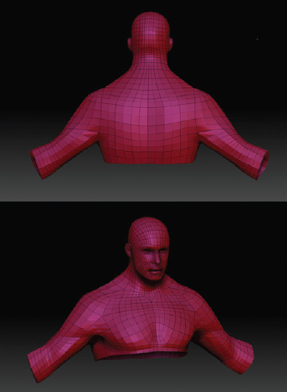
The shoulder is another region of high deformation that requires some specifc loops to allow for realistic movement in animation. In Chapter 5, I discussed the shoulder girdle and the range of motion it is capable of doing. To accommodate this general deformation, you need to loop the shoulders in a way that allows the most flexibility in animation. Here you will use the "cape" loop popularized by Jeff Unay in Maya Hyper-Realistic Creature Creation: A hands-on introduction to key tools and techniques in Autodesk Maya (Autodesk Maya Press, 2008).
Establishing the shoulders in an animation mesh is key to creating a fluid animation. The perfect shoulder topology will take on a cape form, as shown in Figure 8.13.
Once the cape is established, be sure to create topology that follows the Deltoids into the Pectoralis major, as shown in Figure 8.14. The cape is key to the rotation of the shoulder, so make sure that the topology establishes the form of the Deltoid.
As you move down the arm to the elbow, make sure to create at least a minimum of three to four edge loops for the elbow to allow a natural bend, as shown in Figure 8.15.
The wrist will have a great deal of movement in the ulna and radius, so be sure to create enough edge loops to capture the full range of the wrist, as shown in Figure 8.16.


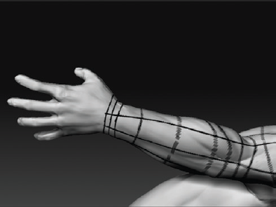
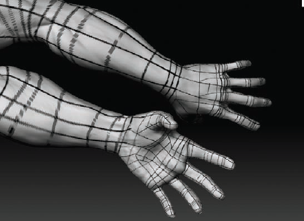
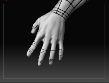
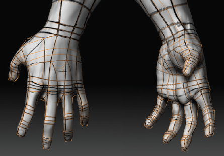
The hand has several planes, which makes it diffcult to maintain a quad poly mesh, as shown in Figure 8.17. Be sure to draw the topology to fit an animation, but also keep the form of the hand, avoiding creating triangles or ngons (faces with more than four points). Although triangles are acceptable if hidden in unobtrusive areas and kept to a minimum, ngons should never be left in the mesh.
Ngons and triangles can produce a pinch or unfavorable result during animation. The first lines to establish on the hand are the edge loops around knuckles, as shown in Figure 8.18. Be sure to have at least five total faces wrapping around each finger, as shown in Figure 8.19. If you have just four faces, ZBrush will often interpret it incorrectly during projection.
You will now move on to the torso of the figure. You will lay out the edge loops to define the core of the body as well as the legs and feet of the figure. As you work, you should be sensitive to areas of high deformation so you can place your edge flows to allow for maximum range of motion when the figure is animated. Be sure to follow the form of the core and add edge loops at key pivot points of the mesh. The knees, ankles, and toes are key for creating a mesh that will animate well. These are the key pivot points of a mesh for animation; be sure to add edge loops here.
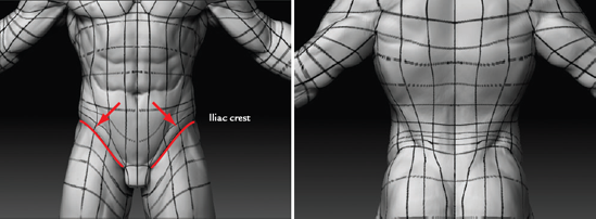
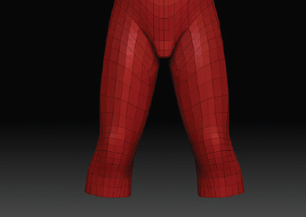
Much movement will happen for a figure at the core. This is where the topology flow must follow the form of your sculpt. You will notice in Figure 8.20 that the topology will follow the Gluteus maximus and the iliac crest.
As you move down the leg to the patella, there will need to be a minimum of four to five edge loops around the knee. There will be severe pinching in the Biceps femo-ris if there is not enough topology in the area. As you can see from Figure 8.21, the edge loops start at the base of the Vastus medialis, and the last loop ends at the tibial tuberosit y.
Down the tibia bone, you continue to the ankle, where the next set of edge loops must be applied. In Figure 8.22 you will notice that I have drawn lines that take on the shape of the ankle and calf.
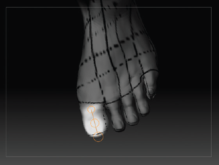
As you move down the foot to the toes, the best solution for drawing your topology is to use ZBrush's topology masking. First make sure that X symmetry is on so that the topology lines are drawn on both big toes. Switch from draw mode into move mode at the top of the interface. Once you are in the move mode, you can create a topology mask by holding Ctrl. Place your brush at the first joint of the big toe, and draw your topology mask just like Figure 8.23.
Once you have the mask, press Ctrl, and click the canvas to inverse the mask. Alternatively, you can go to the Tool palette, select Masking, and click Inverse. Then, once the mask is inverted so that only the big toe is masked (Figure 8.24), go back into the Masking menu and select HidePt. This will hide anything that is not masked. Now you will be able to draw the perfect topology lines.
Repeat steps 4 and 5 for every toe.


With all the topology lines being worked out ahead of time, creating the new topology will be an extremely easy process. It will be a simple matter of tracing the lines you have just taken the time to plan.

At this point, there is one thing you need to take care of—you need to open the mouth in order to create topology for both lips without intersecting the upper lip with the bottom. You will use the Masking, Transpose, and Polygroups menus to open the mouth. With the mouth open, you'll be able to continue your edge loops down into the inner lip area instead of having the mouth mesh end abruptly at the line of the lips.
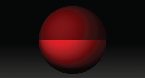
First you need to drop the mesh to its lowest subdivision level and use a Lasso to select the lower mandible. Remember to select a piece of your mesh, hold down Shift+Ctrl, and click the canvas to drag out your selection. However, this time you will let go of Shift, and the box will turn red. This is telling ZBrush to hide what is in the red. It should look like Figure 8.25. Once you have the mandible hidden, turn on PolyFrame mode by pressing Shift+F or selecting from the menu on the right side of the screen. Then click Group Visible in the Polygroup menu, which you can find by going to the Tool palette and selecting Polygroups. Your mesh will change color. This has just made the rest of the head its own polygroup.
Show your entire mesh again by holding Shift+Ctrl and clicking inside the canvas. Go to the midsubdivision level of the body. We don't want too many faces here to work with, so level 3 should be fine. Select the head polygroup by holding Shift+Ctrl, and click the head polygroup that you just made. This will hide the mandible. Under Masking in the Tool palette, click the Mask All option. This will mask the head. Now bring the mandible back by holding Shift+Ctrl, and click the canvas. Now your mandible will not be masked. You should have a masking like Figure 8.26 that is ready to move the bottom part of the mouth. Click Rotate at the top of the interface, and draw out your action line. Now grab the middle of the last circle that is in front of the jaw and pull down. You'll end up with an open mouth much like Figure 8.27.


Now that you have laid out your topology lines, you can construct the new topology. This will be a quick and easy process, thanks to the polypainting you did first. Keep in mind that it is OK not to follow these polypainting lines exactly. Sometimes there are changes that become apparent as you start laying in the edge loops. Don't consider the map to be absolutely necessary—it is there to assist you.
To create new topology in ZBrush, you will be using a ZSphere. Make sure that your ZTool sculpt is loaded. Go to Tool, and select the ZSphere. Drag a ZSphere onto the canvas (Figure 8.28), and put it in edit mode. Move down the Tool palette until you come across the Rigging menu, and click Select Mesh.
A pop-up window will open for you to select your sculpted mesh. Once you have selected your sculpt (Figure 8.29), move to the Topology menu, and select Edit Topology. You are now able to create new animation-ready topology. Before you begin to lay down the topology, click in the empty canvas a few times to unselect the ZSphere.
Let's begin with the head of your sculpt. ZBrush's retopology tools are a basic click-one-vertex-at-a-time system. Before you begin building the topology, drop your brush size to 1. When you click your mesh, you will see a red circle. Continue to click three other circles to form a poly face. You will notice that when you close a poly face off, the red circle will have two white triangles, as you can see in Figure 8.30. This is letting you know that the starting point of your next vertex will begin from the red circle, as you can clearly see in Figure 8.31.
To begin with the face, the first step is to establish the edge loops around the eye. In Figure 8.32 you can see the edge loop of the eye, and in Figure 8.33 you can see the resulting mesh from the topology. To view your mesh, go to the Tool palette, select the Adaptive Skin menu, and click the Preview button. The shortcut to this is the A key. This will display your mesh at a density level of 2. If you adjust the density level, ZBrush will subdivide your mesh by that number. When you finish the topology, this number will dictate the number of subdivision levels your mesh will have. Continue adding the edge loops for the eyes so that you get to the result of Figure 8.34.
Continue to build the topology down to the nose. As you can see in Figure 8.35, I had to change my edges a little from the original polypaint. I did not factor in the loop at the end of the nose. Once you complete the nose, you should get something like Figure 8.36.
Now move to the mouth, where you must have several edge loops to capture the extreme movements outward that mouths can make. Figure 8.37 will show the topology edge loops for the mouth.
Once the mouth has been completed, you can finish the rest of the head off except the ears, as shown in Figure 8.38. It is a good idea to keep previewing your mesh as you build by using the A key. Once you have completed the ears, as shown in Figure 8.39, you can move on to the Deltoids.


The shoulders seem to be the easiest features to create; however, often people do not create accurate animation topology for this area of the anatomy. You must be sure to create geometry that resembles a cape over the shoulders, as you can see in Figure 8.40. This will give the mesh result shown in Figure 8.41; the finished shoulders with the armpits will look like Figure 8.42.
Make sure to draw out the arms as basic cylinders with several edge loops around the joint, as you can see in Figure 8.43.
As you build the topology down the arm to the wrist, make sure to have enough edge loops at the wrist to capture the range of motion that this part of the anatomy has, as you can see in Figure 8.44.
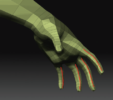
The hand is the area that could change the most from your polypaint. As you can see in Figure 8.45, at first I stayed with the painted lines. However, by the time I was done, I had added many faces to create a more animation-ready hand, which is shown in Figure 8.46.
The torso is as basic as it gets, except when you build up the iliac crest or at the bend of the waist. Usually you will be able to determine whether more edge loops are required. As you can see in Figure 8.47, I stayed consistent with the polypaint. The torso was followed exactly to the polypaint. In Figure 8.48, you can see that I continued to work down the torso into the genitals and Gluteus maximus.
The leg is much like the arm in that it takes on a cylinder shape but must have at least four edge loops around the knee and the ankle. You can see in Figure 8.49 how basic the mesh is with just a few tweaks. The ankle's topology does take on some of the characteristics of the sculpture as you build the topology in the general shape of the ankle; see Figure 8.50.
once you get past the ankle, you are in the home stretch on your way to the feet. The feet are much like the hands in that there will be a little tweaking needed to have a quality flow of quads, and as you can see in Figure 8.51, you will need several edge loops to establish a foot that can be animated.
Now you have constructed a complete animation-ready mesh with ZBrush's topology tools. Your finished mesh should look something like Figure 8.52, depending on your topology flow.
To create a new ZTool, simply click the Make Adaptive Skin button under the Adaptive Skin menu. If you wish to project the sculpt into your new animated-ready mesh, make sure that projection is on in the Tool → Projection menu, and set the density in Tool → Adaptive Skin to a level high enough to capture the sculpt. In most cases, having the Density slider set to 4 or 5 will capture all of the mesh. However, this is a setting that will be adjusted on a per-mesh basis. This will project the sculpted detail into the new topology and create a new ZTool in your Tool palette. You may notice that the polypaint also transfers. This can be useful if you need to transfer both sculpture as well as texture detail from one mesh to another.


Now that you have seen how to use the topology tools, let's look at an entirely different approach to remeshing. In this section, I'll show how to use a third-party Maya plug-in called NEX.
Once NEX is installed, you'll begin with a topology map drawn in ZBrush using polypainting just as you did earlier in this chapter. Although a topology map is not necessary, it is a useful tool to help you plan the edge flow ahead of time and give yourself a guide for at least the starting loops. I find it useful to begin a mesh, although often the end topology will deviate somewhat from the original plan.
NEX is included as a demo on this book's DVD. You can download it and several instruc-tional videos at draster.com. After running the installer, you will need to activate NEX in Maya. NEX has many extremely valuable modeling tools, and in this section I will only scratch the surface by covering one called Quad Draw. I encourage you to look at the videos of other NEX tools and see how it can be further incorporated into your workflow. Take the following steps to configure NEX as a Maya plug-in:
Run the NEX installer. When this is complete, start Maya.
In the Maya interface, select Windows → Settings And Preferences → Plug-In Manager.
Make sure to select Loaded and Auto Load on the line marked dRasterMaya.mll (Figure 8.53). This ensures that NEX will load every time Maya starts and is always available.

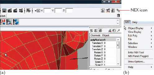
NEX is now loaded and ready for use. You can access the NEX panel in the user interface in one of two ways. The first is clicking the NEX icon in the upper-right corner of the screen, shown in Figure 8.54(a). You can also invoke the NEX panel by clicking the NEX menu in Polygon menu and selecting NEX Panel (Figure 8.54(b)).
You will begin by loading the head model into Maya. This model is included on the DVD as
basehead.obj. This is an export of the midsubdivision level from ZBrush. When I exported, I made sure the polygon count was less than 1 million, since I know my system cannot handle that many polygons in Maya. It is only important to have enough faces to represent the major forms of the high-resolution mesh. Import the model by selecting File → Import in Maya.When you load the model into ZBrush, you will want to add the topology guide map. This map is also included as a TIFF file on the DVD as
topoMap_head.tif. To add it to the mesh session, add a new Blinn shader to the head geometry. Open the Attribute Editor for the shader, and in the Color channel, attach the topology guide map (Figure 8.55).To help isolate the base model so that you don't accidentally select it while you are working, create a new layer for it called base head. Add the head model, and set the layer to Reference. This way, you can see and draw topology on the head, but you cannot accidentally select the geometry.
At this stage, also turn on X-ray shading mode. Because you will be building new faces that often will appear just inside the surface of the base model, you need some way to see both the base model and the new faces. If you don't activate X-ray shading mode, you won't be able to see the topology as you work. X-ray shading is accessed via the viewport Shading menu option (Figure 8.56). Figure 8.57 shows the head loaded into the basehead layer and X-ray shading on.
Because you have a map on the base head and X-ray shading turned on, some of these illustrations may look a little strange. I assure you that when you are rotating the model around it is much easier to see what you are doing while you work. You can always toggle off X-ray as well as the basehead layer's visibility if you find you are getting lost.
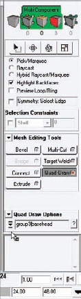
Make sure nothing is selected, and activate the NEX menu by clicking the icon in the upper right of the screen. Click the Quad Draw button, and from its option menu, select the base head. This tells NEX you will be drawing new polygons on the surface of the basehead object. Figure 8.58 shows the screen with Quad Draw activated.
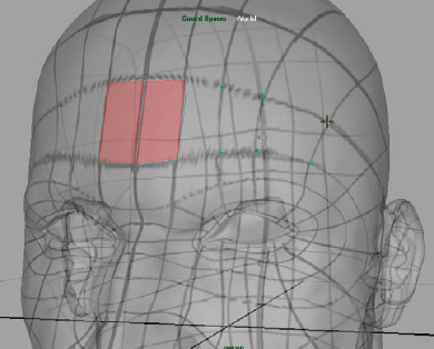
Draw the first face by placing four dots where the vertices should be. You will place these dots by clicking each point intersection on the topology guide map, as shown in Figure 8.59. Although Quad Draw is activated, these dots appear as green points on the model. If you make a mistake and need to move a point, simply drag it with the middle mouse button to where you want it to be. If you need to delete a point, hold down Ctrl. Notice that your pointer now has an X on it. Drag across any points or faces you want to remove, and they will disappear when you release the mouse.
To generate a polygon face from these points, hold down the Shift key, and click in the middle of these four points; a face will be generated. Before you continue to work, you'll want to set this up so that the new faces are shaded differently from the originals, and you'll also want to activate mirror mode. Exit quad draw mode by clicking the quad draw button again. Press F8 to enter object mode, and select the new face. With the face selected, add a Blinn shader, and set the color to a light red, as shown in Figure 8.60. This will help you clearly see the new topology as it is built.
You want to mirror this as an instance to the other side of the head so you can see the mesh grow on both sides. With the face selected, select Edit → Duplicate Special. In the Duplicate Special Options dialog box, select Instance as the geometry type, and enter –1 in the X scale field (Figure 8.61). Click OK, and the face will now mirror to the other side.
The next stage of creating the initial mesh is to draw new faces.
With the new face selected, enter Quad Draw again. NEX will understand that you want to add to the selected topology. Draw more points based on the guide map, as shown in Figure 8.62. Remember that to build faces for each set of four points, hold down Shift and click inside each of the four new faces to generate the polygon (Figure 8.63).
Figure 8.64 shows the eye area generated in this manner. Notice the empty triangle area on the side of the nose. You will correct this later using the standard Maya polygon tools. Often you will need to finesse the topology beyond what you originally planned in the guide map.
At this point, it is a matter of tracing the guide topology of the face and drawing new topology as you go (Figure 8.65).
In the nose area, continue the loop under the nostrils (Figure 8.66). As I mentioned, the guide map is only a guide, and the topology may change. Exit Quad Draw, and select the Cut Polygon tool. In Figure 8.67 you can see me redirect these edges so the loop continues down under the nose.
Continue around the mouth, as shown in Figure 8.68.
In Quad Draw, you can move components like edges and points. In Figure 8.69 I have moved the edges around the mouth to the very center of the lips. To move a component, hover over a point or edge, and then drag with the middle mouse button to move it. As it moves, it will remain "stuck" to the basehead surface.
You will now cut a new loop in these long faces. Hold down Shift, and a dotted line will appear, previewing the new edge loop. Move the mouse while holding down Shift, and you will see how interactive placement of the loop is possible. Click to execute this loop.
Figure 8.70 shows the face topology as it stands so far. I have turned off visibility on the head layer to make it easier to see in the image. At this point, you will build the remainder of the topology to the neck and back of head, leaving the ears for last.
Continue to build the faces surrounding the ear area (Figure 8.71). I like to leave the ears for last, since often I will need to add more loops from the ears to define their shapes. Having the rest of the head in place makes it easier to determine where these loops will ultimately flow.
Zoom into the ear area, and start building faces based on the guide map (Figure 8.72). This is a tight area, and it can be easy to get lost here. I usually take it slow and aim to create as many quads as possible. Usually ears need to be reworked a bit manually by cutting new edges and adding new faces before they are perfect. The process of adding these faces with NEX will save you a lot of time (Figure 8.73).


At this point, you have built your base mesh using NEX. Now you will leave NEX and use the Maya polygon tools to refine the flow of the ears and the eye and mouth areas.
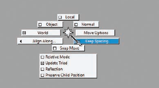
First you will want to snap the midline and duplicate the model as a copy instead of an instance. Delete the copied side of the model, as shown in Figure 8.74. Select the edges that run down the centerline of the face. This can be done by selecting an edge and then pressing the right arrow key. Make sure to deselect any extra edges in the shoulders or mouth area.
Convert this edge selection to points by pressing Ctrl+F9. With the vertices of the midline selected, press the W key to enter move mode. Hold down the X key, and move the vertices toward the centerline. They will snap along this line, closing any gaps. If this does not work, then you need to turn off Keep Spacing on the Move tool. Hold down the W key and the left mouse button to see the Move marking menu; make sure Keep Spacing is deselected (Figure 8.75).
With the mesh selected, click Edit → Duplicate Special, and in the option box, set From Instance to Copy. Click the Duplicate Special button, which will make a new copy of the mesh mirrored on the opposite side.
Select both sides, and click Mesh ?Combine to merge them into one model. Now, to merge the vertices down the centerline, go into vertex mode, and select the center verts of the head (Figure 8.76). Click Edit Mesh → Merge Options. In the option box, set the threshold to .05, and click Merge to merge the points of the centerline.
You may want to check to make sure the points have merged by turning on Border Edge view. Go to Display → Polygons → Custom Polygon Display, and make sure Border Edges is on. Click Apply and Close, and now the edges between unmerged verts will be highlighted in green.
Check the model to be sure all the center vertices are merged. Figure 8.77 shows the topology at this stage.


In this section, you will add the internal structure of the character's mouth as well as the thickness of the eyelids. The inside of the mouth is called the mouth bag, and it is there to prevent you from seeing into the character's skull when he opens his mouth. The video for this process is included on the DVD.
At this point, you will extrude the eyelids inward and create a mouth bag. The eyelid extrusion is to help add thickness to the lids, and the mouth bag exists to keep the head from appearing empty when the mouth is opened.
To extrude the eyelids, select one edge from both eyeholes. Select Mesh → Fill Hole to create a polygon face in the hole, as shown in Figure 8.78.
Click Edit Mesh, and make sure Keep Faces Together is on. Now click Extrude (Figure 8.79). Use the Move Manipulator to extrude the face back into the head, giving thickness to the eyelid. You can repeat this extrusion multiple times to add edge loops by pressing the G hotkey. This will repeat the last command in Maya.
To generate the mouth bag, fill the mouth hole by selecting an edge and then selecting Mesh → Fill Hole. Extrude this face into the head (Figure 8.80).
Rotate to the inside of the head, select the points of the mouth face, and spread them out into the shape of the mouth cavity. Once you have a suitable space created, select the mouth face, and extrude it back again into the head (Figure 8.81). Once you are halfway in, rotate the faces (Figure 8.82), and extrude them down the throat, scaling them down. Now you can delete the mouth face.
Finally, remove the triangle at the bridge of the nose by selecting one edge and using the To Edge Ring And Collapse function in the Edit Mesh marking menu. You can find this by selecting an edge, holding down Ctrl, and clicking the edge. From the Marking menu, select Edge Ring and then To Edge Ring And Collapse.


The base mesh is now complete. At this stage, I will show you how to take this new ordered base mesh and apply it to your ZTool, creating a new ZTool that retains all your sculpted work but uses the new low-resolution topology.
This process is shown on video that is available on the DVD. Please refer to this video for more information.
The ZTool of this demo is also available on the DVD. In it you will find the high resolution head as well as the remeshed low-resolution base appended as a subtool. The two heads sit on top of each other in 3D space. In this section, you'll learn two ways to use this remeshed base. The first technique will create a new ZTool with the new topology.
Select the Base Mesh subtool. Turn on double-sided view by selecting Tool → Display Properties → Double.
Load the
headZtool.ztlmodel from the DVD. Draw it on the canvas, and go into edit mode with the T key. You will notice there are two subtools: the high-resolution head and the new low-resolution topology. Select the remeshed head, and make sure it is the active subtool. Hide the highresolution head by turning off its visibility icon in the SubTool menu. With the low-resolution head selected, use a show marquee to hide the back of the head so you can see the mouth bag (Figure 8.83).Press the W key to enter transpose mode. You will use topology masking to mask the outside of the head down to the lips, leaving the mouth bag unmasked. Hold down Ctrl and drag toward the mouth to mask the face (Figure 8.84).
Now, rotating to the back of the head, you can see inside that the mouth bag is unmasked. Ctrl-click the background to invert the mask for the mouth bag, which is now masked (Figure 8.85). You want to now polygroup the mouth bag separately from the head. To do this, select Tool → Masking → Hide Pt. This hides any unmasked faces.
The mouth bag will now be isolated on-screen. Select Tool → Polygroups → Group Visible to polygroup the mouth bag faces.
You may want to also polygroup the faces of the inner eye with the same technique. This is shown in detail on the DVD video for this tutorial.
At this stage, with all the new geometry polygrouped, divide the head to four subdivision levels, and store a morph target by selecting Tool → Morph Target → Store MT.
Turn on the visibility of the high-resolution head by clicking into the eyeball icon in the SubTool menu.
With both tools visible and the remeshed head still selected, click the Project All button in the SubTool menu. This will project the remeshed head onto the original head. Notice that this will create strange spikes in the geometry (Figure 8.86). This is a result of the mouth bag trying to project as well. That is why you polygrouped it and stored a morph target. You can also reduce issues like this using the PA Dist and PA Blur sliders discussed in the following sidebar.
Note
Under ProjectAll in the Subtool menu, you will find two sliders called PA Dist and PA Blur. These stand for Project All Distance and Project All Blur. Using these sliders can help prevent the mouth bag from projecting into the mesh. I included this process since it will always work in those cases where the sliders may not be able to stop all the points from projecting. PA Distance adjusts the project distance of the mesh and is useful for tweaking tight areas like between fingers and toes. PA Blur smoothes the mesh while projecting, giving you further control when areas are problematic. These sliders are best used by hiding parts of the mesh, applying your PA Dist and PA Blur settings, and using Project All on isolated areas of the model. These settings will differ for every model, so it is important to experiment with them to find what works best in each scenario.
Hide the high-resolution head again, and click Switch under Tool → Morph Target. Hold down Ctrl+Shift and click the head so only the polygrouped mouth bag is visible mask this, and show the head again. From the Brush menu, select the Morph brush (Figure 8.87). Turn up ZIntensity to 100, and turn on X symmetry. Brush around the surface to restore the detail while keeping the mouth bag isolated (Figure 8.88).


You have now successfully restored the detail to the head without the problem of the mouth bag trying to project as well. Often this process will require some resculpting at the lip and eye seams, but it is a huge time-saver compared to resculpting an entire model.

In this chapter, you saw how logical edge flow is beneficial in that it allows for more natural deformations in animation. It also supports the texture artist by giving logical places to split the UV seams as well as helping to keep textures from stretching during animation. You have seen two different approaches to remeshing a model as well as some tricks to adding geometry to a ZTool without disturbing the high-resolution levels.