
14
Interrupts
New instructions used in this chapter:
We all know what interrupts are and we don't like being interrupted. We are busy doing something and the phone rings or someone arrives at the door.
If we are expecting someone, we could look out of the window every now and again to see if they had arrived or we could carry on with what we are doing until the doorbell rings. These are two ways of receiving an interrupt. The first when we keep checking in software terms is called polling, the second when the bell rings is equivalent to the hardware interrupt.
We have looked at polling when we used the keypad to see if any keys had been pressed. We will now look at the interrupt generated by the hardware.
Before moving onto an example of an interrupt consider the action of the door in a washing machine. The washing cycle does not start until the door is closed, but after that the door does not take any part in the program. But what if a child opens the door, water could spill out or worse!! We need to switch off the outputs if the door is opened. To keep looking at the door at frequent intervals in the program (software polling) would be very tedious indeed, so we use a hardware interrupt. We carry on with the program and ignore the door. But if the door is opened the interrupt switches off the outputs – spin motor etc. If the door had been opened accidentally then closing the door would return back to the program for the cycle to continue.
This suggests that when an interrupt occurs we need to remember what the contents of the files were. i.e. the STATUS register, W register, TMR0 and PORT settings so that when we return from the interrupt the settings are restored. If we did not remember the settings, we could not continue where we left off, because the interrupt switches off all the outputs and the W register would also be altered, at the very least.
Interrupt sources
The 16F84 has 4 interrupt sources.
The 16F818/9 has 9 interrupt sources, and of course need extra bits in the interrupt registers to handle them. The additional interrups used in the 16F818/9 are
These interrupts can be enabled or disabled as required by their own interrupt enable/disable bits. These bits can be found in the interrupt control register INTCON for the 16F84 and also on the Peripheral Interrupt Enable Register1, PIE1 on the 16F818/9.
In this section we will be looking at the interrupt caused by a rising or falling edge on PORTB,0.
Interrupt control register
The Interrupt Control Register INTCON, file 0Bh is shown in Figure 14.1.
![]()
Figure 14.1 The interrupt control register, INTCON of 16F84
Bit 6 in this register is designated as the Peripheral Interrupt Enable Bit, PEIE for the 16F818/9.
Before any of the individual enable bits can be switched ON, the Global Interrupt Enable (GIE) bit 7 must be set, i.e. a 1 enables all unmasked interrupts and a 0 disables all interrupts.
| Bit 6 | EEIE (16F84) is an EEPROM data write complete interrupt enable bit, a 1 enables this interrupt and a 0 disables it. |
| Bit 6 | PEIE (16F818/9) is the bit that permits enabling of the extra, peripheral bits. |
| Bit 5 | T0IE is the TMR0 overflow interrupt enable bit, a 1 enables this interrupt and a 0 disables it. |
| Bit 4 | INTE is the RB0/INT Interrupt Enable bit, a 1 enables this interrupt and a 0 disables it. |
| Bit 3 | RBIE is the RB Port change (B4-B7) Interrupt enable bit, a 1 enables it and a 0 disables it. |
| Bit 2 | T0IF is the flag, which indicates TMR0 has overflowed to generate the interrupt. 1 indicates TMR0 has overflowed, 0 indicates it hasn't. This bit must be cleared in software. |
| Bit 1 | INTF is the RB0/INT Interrupt flag bit which indicates a change on PORTB,0. A 1indicates a change has occurred, a 0 indicates it hasn't. |
| Bit 0 | RBIF is the RB PORT Change Interrupt flag bit. A 1 indicates that one of the inputs PORTB,4–7 has changed state. This bit must be cleared in software. A 0 indicates that none of the PORTB,4-7 bits have changed. |
Program using an interrupt
As an example of how an interrupt works consider the following example:
Suppose we have 4 lights flashing consecutively for 5 seconds each. A switch connected to B0 acts as an interrupt so that when B0 is at a logic 0 an interrupt routine is called. This interrupt routine flashes all 4 lights ON and OFF twice at 1 second intervals and then returns back to the program providing the switch on B0 is at a logic1.
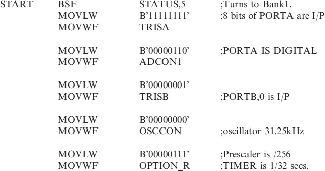
I have used the 16F818 for this application.
The circuit diagram for this application is shown in Figure 14.2.
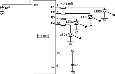
Figure 14.2 Interrupt demonstration circuit
One thing to note from the circuit the 16F818 chip has internal pull-up resistors on PORTB so B0 does not need a pull up resistor on the switch.
The interrupt we are using is a change on B0, we are therefore concerned with the following bits in the INTCON register, i.e. INTE bit4 the enable bit and INTF bit1 the flag showing B0 has changed, and of course GIE bit7 the Global Interrupt Enable Bit.
Program operation
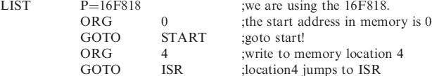
When B0 generates an interrupt the program branches to the interrupt service routine. Where? Program memory location 4 tells the Microcontroller where to go to find the interrupt service routine.
Program memory location 4 is then programmed using the org statement as:
| ORG | 4 | ;write next instruction in program memory location 4 |
| GOTO | ISR | ;jump to the Interrupt Service Routine. |
The interrupt service routine
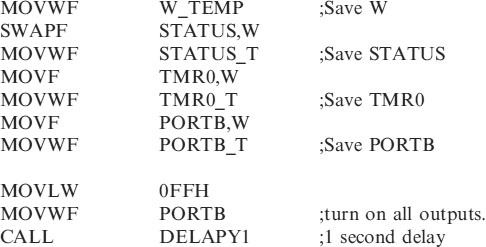
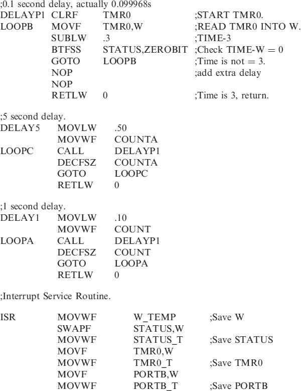
The Interrupt Service Routine, ISR, is written like a subroutine and is shown below:
;Interrupt Service Routine
Operation of the interrupt service routine
The interrupt service routine operates in the following way.
• When an interrupt is made the Global Interrupt Enable is cleared automatically (disabled) to switch off all further interrupts. We would not wish to be interrupted while we are being interrupted.
• The registers W, STATUS, TMR0 and PORTB are saved in temporary locations W_TEMP, STATUS_T, TMR0_T and PORTB_T.
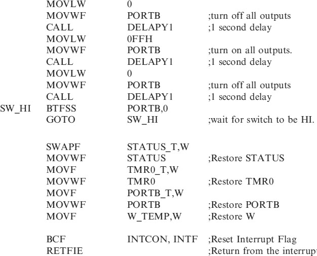
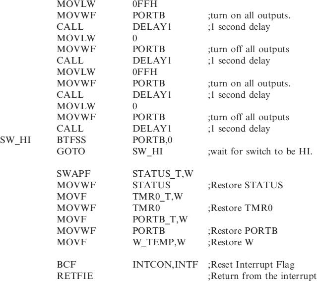
• The interrupt routine is executed, the lights flash on and off twice. This is a separate sequence than before to show the interrupt has interrupted the normal flow of the program. NB. The program has not been looking at the switch that generated the interrupt.
• We then wait until the switch returns HI.
• The temporary files W_TEMP, STATUS_T, TMR0_T and PORTB_T are restored back into W, STATUS, TMR0 and PORTB.
• The PORTB,0 interrupt flag INTCON,INTF is cleared ready to indicate further interrupts.
• We return from the interrupt, and the Global Interrupt Enable bit is automatically set to enable further interrupts.
Program of the interrupt demonstration
The complete code for this program is shown below as INTFLASH.ASM.
;INTFLASH.ASM Flashing lights being interrupted by a switch on B0.
;Using 16F818
;EQUATES SECTION
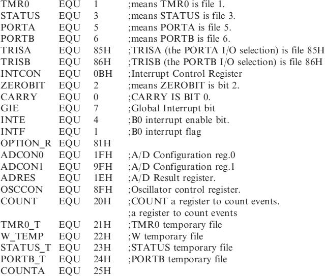
;*********************************************************
;*********************************************************
;Configuration Bits
| __CONFIG H′3F10′ | ;sets INTRC-A6 is port I/O, WDT off, PUT |
| ;on, MCLR tied to VDD A5 is I/O | |
| ;BOD off, LVP disabled, EE protect disabled, | |
| ;Flash Program Write disabled, | |
| ;Background Debugger Mode disabled, CCP | |
| ;function on B2, | |
| ;Code Protection disabled. |
;*********************************************************
;*********************************************************
;*********************************************************
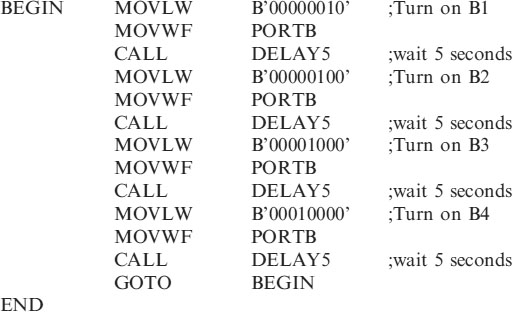
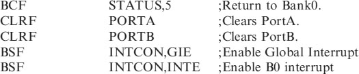
The 4 lights are flashing on and off slowly enough (5 second intervals) so that you can interrupt part way through taking B0 low via the switch, (make sure B0 is hi when starting). The interrupt service routine then flashes all the lights on and off twice at 1 second intervals.
When returning from the interrupt with B0 hi again, the program resumes from where it left off, i.e. if the 2nd LED had been on for 3 seconds it would come back on for the remaining 2 seconds and the sequence would continue.