
4
Headers, porting code – which micro
Arizona Microchip the manufacturers of the PIC Microcontroller make over 100 different types of microcontroller. How do we choose the correct one for the job?
Factors affecting the choice of the microcontroller
When deciding on which Microcontroller to use for your application there are a number of factors you will need to consider.
• How many inputs and outputs do you need. If you are using the program FLASHER.ASM which only flashes 1 LED on and off then any PIC will do this. If you are turning 8 outputs on and off then you will need a microcontroller that has at least 8 I/O (of course). So an 8pin micro i.e. 12F629 will not do because it only has 6 I/O.
• Do you need accurate timing? If so then you will need to add a crystal to your micro to provide the clock. If timing is not that critical then you can use a micro that has an on board oscillator such as the 16F818. You can then omit the crystal and 2 capacitors. The timing accuracy is about 1%. This would do for FLASHER.ASM but not for a 24 hour clock. 1% is about 14 minutes a day.
• Are you making analogue measurements? If so you will need a micro with an AtoD converter on it. The 16F818 has a 5 channel, 10 bit AtoD converter. If you need more that 5 channels then you will need to use a micro with more AtoD channels such as the 16F877 which has 8.
• What operating frequency do you require? The greater the frequency the faster your code will execute. Most newer devices can operate up to 20MHz, some even faster. Some older devices can only achieve 4MHz. The programs in this book only require an operating speed of 4MHz.
• How many instructions are there in your program? The 16F818 has space for 1k i.e. 1024 instructions. The 16F877 has 8k program memory locations. All programs in this book require less than 1k of program memory space.
• How many memory locations are required to store data? The 16F818 has 128 bytes of data memory, the 16F877 has 368.
• Do you need to store data so that it will be saved if the power is removed or lost? If so you need a micro with EEPROM data memory. The 16F818 has 128 bytes of EEPROM memory, the 16F877 has 256.
There may be other requirements that you need from your micro, which are not considered in this book, such as:
Choosing the microcontroller
As I mentioned previously the FLASHER.ASM program which flashes 1 LED on and off can be performed by any Micro. Well, that has narrowed the field down! So which microcontroller do we use for that application? If you were mass producing these flasher units the answer would probably be – use the cheapest and smallest – the 12C508 is possibly the device then. But for small scale production or one offs you will probably have (or develop) a favorite. Probably the most common chip used by the beginner is the 16F84; this has been around since about 1998. This micro has built up a very large fan base which is why it is still widely used. People are using this chip because they are used to using it! There is now another micro on the market which will do everything that the 16F84 can do and more. This device is the 16F818.
The data sheets for the 16F84 and 16F818 are shown in Figures 4.1 and 4.2 respectively.
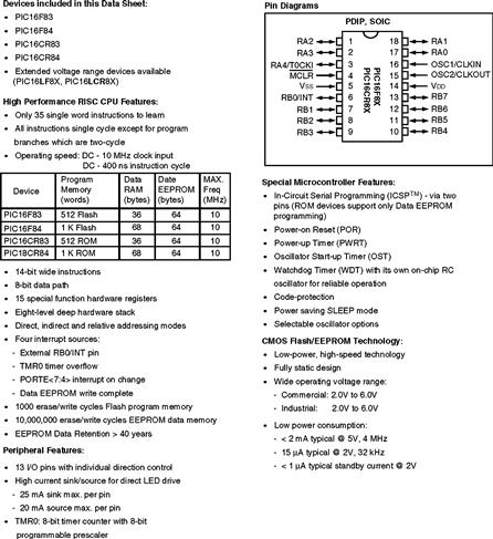
Figure 4.1 The PIC 16F84 data sheet
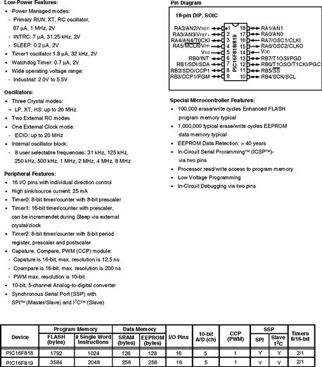
Figure 4.2 The PIC 16F818 and 16F819 data sheet
The main differences are that the 16F818 has 16 I/O, an on board oscillator with 8 selectable frequencies, 128 bytes of data RAM, 128 bytes of EEPROM, 3 Timers one of them a 16 bit, 5 channel 10 bit AtoD converter. The 16F84 has 13 I/O, no on board oscillator, 68 bytes of data RAM, 64 bytes of EEPROM, 1 timer, no AtoD. The most surprising difference of all is that the 16F84 is about 3 times the price of the 16F818!!
The programs in this book consist of 2 parts:
• A header section which tells the ‘build’ software which device we are using, configures the device, i.e. defines which pins are inputs and outputs, sets the timer rate and includes some timing delays if you require them in a subroutine section.
• The second part of the program, entitled, ‘Program starts now’, is where you write the code to perform your application.
The header program is unique to the particular microcontroller being used, but the ‘application code’ entered after “Program starts now”, is specific to the application not the microcontroller. So any microcontroller that has i.e. the required number of I/O or A/D can be used. As I mentioned before any microcontroller can be used to execute the FLASHER.ASM code.
Headers
Just one point before we look at the headers. The 8 pin micros only have 6 I/O, they do not have PORTA and PORTB pins, they have what is called a General Purpose I/O or GPIO. So the instruction BSF PORTB,0 would have to be changed to BSF GPIO,0.
The following headers will be used in this book:
| HEAD12C508. ASM | ; for the 12C508 and 12C509 |
| HEAD12F629. ASM | ; for the 12F629 |
| HEAD12F675. ASM | ; for the 12F675 |
| HEAD16F627. ASM | ; for the 16F627 and 16F628 |
| HEADER84. ASM | ; for the 16F84 |
| HEAD16F818. ASM | ; for the 16F818 and 16F819 |
| HEAD16F872. ASM | ; for the 16F872, 16F874 and 16F877 |
;Uses the internal 4MHz clock.
;**********************************************************
| LIST | P = 12C508 | ;We are using the 12C508. |
| ORG | 0 | ;0 is the start address. |
| GOTO | START | ;goto start! |
;***************************************************
;Configuration Bits
| __CONFIG H’0FEA’ | ;selects Internal RC oscillator, WDT off, |
| ;Code Protection disabled. |
;**********************************************************
;SUBROUTINE SECTION.
;**********************************************************
;CONFIGURATION SECTION.
**********************************************************
;Program starts now.
END
HEAD12F629.ASM FOR 12F629 using 4MHz internal RC
;**********************************************************
| LIST | P = 12F629 | ;We are using the 12F629. |
| ORG | 0 | ;0 is the start address. |
| GOTO | START | ;goto start! |
;***************************************************
;Configuration Bits
| __CONFIG H’3F84’ | ;selects Internal RC oscillator, WDT off, |
| ;Code Protection disabled. |
;**********************************************************
;SUBROUTINE SECTION.

;**********************************************************
;**********************************************************
;Program starts now.
END
;HEAD12F675.ASM FOR 12F675 using 4MHz internal RC.
;**********************************************************
| LIST | P = 12F675 | ;We are using the 12F675. |
| ORG | 0 | ;0 is the start address. |
| GOTO | START | ;goto start! |
;***************************************************
;Configuration Bits
| __CONFIG H’3F84’ | ;selects Internal RC oscillator, WDT off, |
| ;Code Protection disabled. |
;**********************************************************
;SUBROUTINE SECTION.
;**********************************************************
;CONFIGURATION SECTION.

;**********************************************************
END
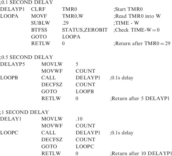
;HEAD16F627.ASM for the 16F627/8, using the 37kHz internal RC
;PortA bits 0 to 7 are inputs
;PortB bits 0 to 7 are outputs
;Prescaler/32
;********************************************
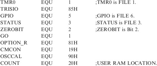
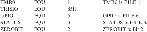
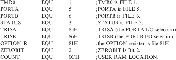
;EQUATES SECTION
| TMR0 | EQU | 1 |
| OPTION_R | EQU | 1 |
| PORTA | EQU | 5 |
| PORTB | EQU | 6 |
| TRISA | EQU | 5 |
| TRISB | EQU | 6 |
| STATUS | EQU | 3 |
| ZEROBIT | EQU | 2 |
| CARRY | EQU | 0 |
| EEADR | EQU | 1BH |
| EEDATA | EQU | 1AH |
| EECON1 | EQU | 1CH |
| EECON2 | EQU | 1DH |
| RD | EQU | 0 |
| WR | EQU | 1 |
| WREN | EQU | 2 |
| PCON | EQU | 0EH |
| COUNT | EQU | 20H |
;*****************************************************
| LIST | P = 16F627 | ;using the 627 |
| ORG | 0 | |
| GOTO | START |
;***************************************************
;Configuration Bits
| __CONFIG H’3F10’ | ;selects Internal RC oscillator, WDT off, |
| ;Code Protection disabled. |
;*******************************************************
;SUBROUTINE SECTION.
;**********************************************************
;*********************************************************
;Program starts now.
END
;HEADER84.ASM for the 16F84 using a 32kHz crystal
;EQUATES SECTION
;**********************************************************
| LIST | P = 16F84 | ;We are using the 16F84. |
| ORG | 0 | ;0 is the start address. |
| GOTO | START | ;goto start! |
;**********************************************************
| __CONFIG H’3FF0’ | ;selects LP oscillator, WDT off, PUT on, |
| ;Code Protection disabled. |
;*****************************************************
;SUBROUTINE SECTION.
;**********************************************************
;CONFIGURATION SECTION.
;**********************************************************
;Program starts now.
END
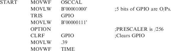
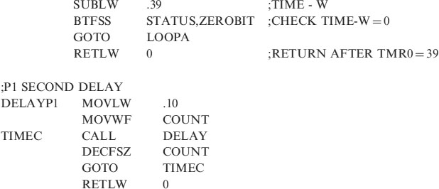
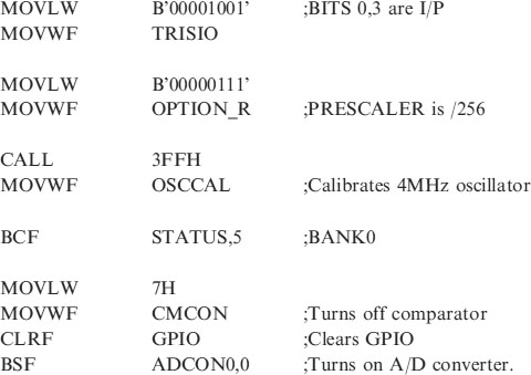
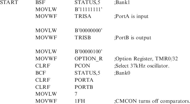
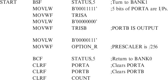
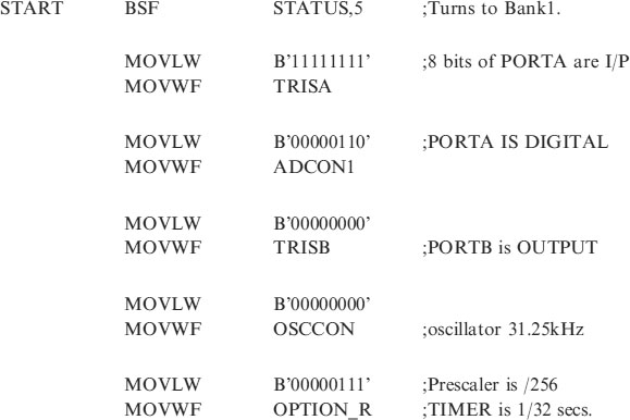
; HEAD818.ASM for 16F818. This sets PORTA as digital INPUT.
;PORTB is an OUTPUT.
;Internal oscillator of 31.25kHz chosen
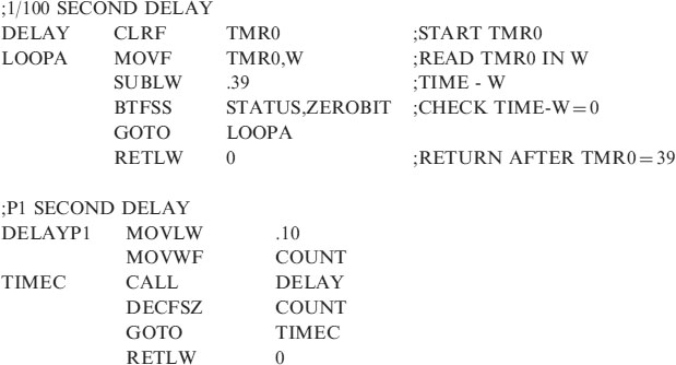
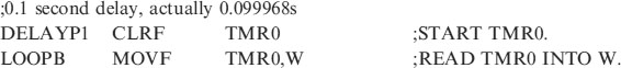
;The OPTION register is set to /256 giving timing pulses 32.768ms.
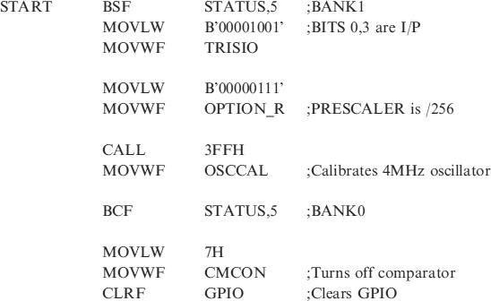
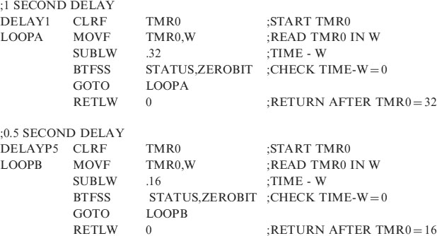
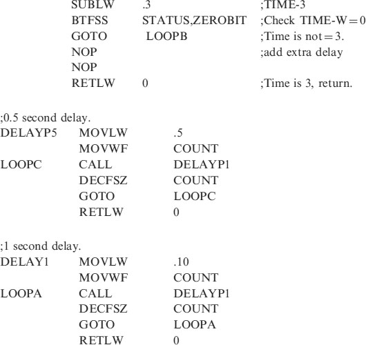
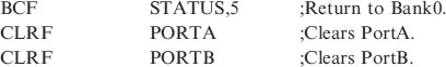
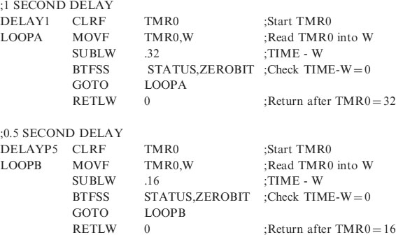
;1second and 0.5 second delays are included in the subroutine section.
;*********************************************************
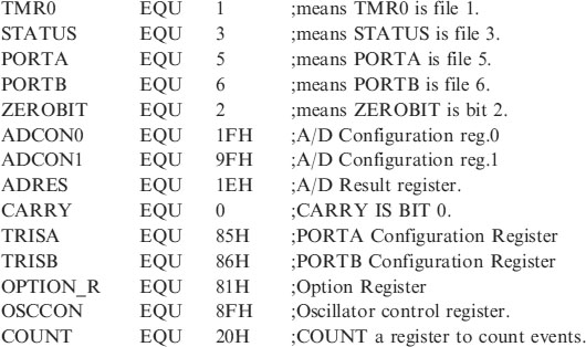
;EQUATES SECTION
;*********************************************************
| LIST | P = 16F818 | ;we are using the 16F818. |
| ORG | 0 | ;the start address in memory is 0 |
| GOTO | START | ;goto start! |
;*********************************************************
;Configuration Bits
| __CONFIG H’3F10’ | ;sets INTRC-A6 is port I/O, WDT off, PUT |
| ;on, MCLR tied to VDD A5 is I/O | |
| ;BOD off, LVP disabled, EE protect disabled, | |
| ;Flash Program Write disabled, | |
| ;Background Debugger Mode disabled, | |
| ;CCP function on B2, | |
| ;Code Protection disabled. |
;*****************************************************
;SUBROUTINE SECTION.
;*********************************************************
;*********************************************************
END
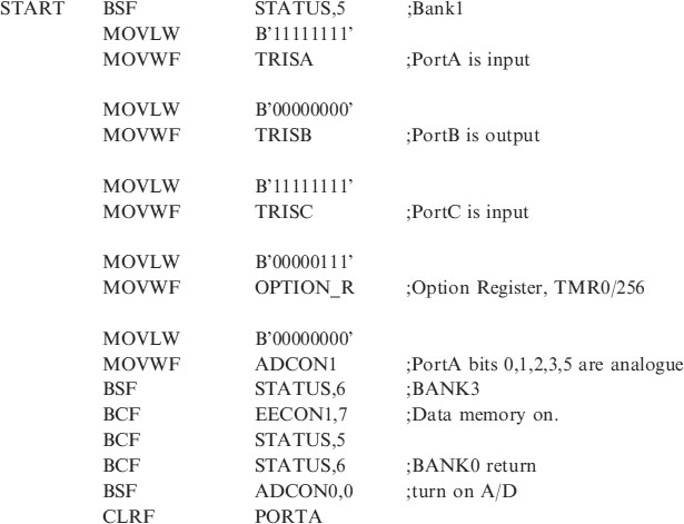
;HEAD872.ASM Header for 16F872 using 32kHz oscillator
;EQUATES SECTION
| TMR0 | EQU | 1 |
| OPTION_R | EQU | 1 |
| PORTA | EQU | 5 |
| PORTB | EQU | 6 |
| PORTC | EQU | 7 |
| TRISA | EQU | 5 |
| TRISB | EQU | 6 |
| TRISC | EQU | 7 |
| STATUS | EQU | 3 |
| ZEROBIT | EQU | 2 |
| CARRY | EQU | 0 |
| EEADR | EQU | 0DH |
| EEDATA | EQU | 0CH |
| EECON1 | EQU | 0CH |
| EECON2 | EQU | 0DH |
| RD | EQU | 0 |
| WR | EQU | 1 |
| WREN | EQU | 2 |
| ADCON0 | EQU | 1FH |
| ADCON1 | EQU | 1FH |
| ADRES | EQU | 1EH |
| CHS0 | EQU | 3 |
| GODONE | EQU | 2 |
| COUNT | EQU | 20H |
;*****************************************************
| LIST | P = 16F872 |
| ORG | 0 |
| GOTO | START |
;*******************************************************
;Configuration Bits
| __CONFIG H’3F30’ | ;selects LP oscillator, WDT off, PUT on, |
| ;Code Protection disabled. |
;*****************************************************
;**********************************************************
;CONFIGURATION SECTION.
![]()
;*********************************************************
END
These headers can be used for applications that use the corresponding microcontrollers. E.g. Any one of them can be used with FLASHER.ASM. Other applications may require functions that are not in all of the devices i.e. AtoD.
The explanation of the operation of the headers will be dealt with later when the individual micros are examined.