
Precision preamplifier ’96, Part II
Morgan Jones raised the excellent point of crosstalk in the input-select switching in a recent article (Valve Preamplifiers, Electronics World, March/ April 1996). If the source impedance is significant then this may be a serious problem.
While I agree that Morgan’s rotary switch with every other contact grounded may be slightly superior to conventional rotary switches, measuring a popular Lorlin switch type showed the improvement to be only 5 dB. I am also unhappy with all those redundant ‘mute’ positions between input selections, so I instead chose interlocked push-switches rather than a rotary. A four-pole-changeover format can then be used to reduce crosstalk.
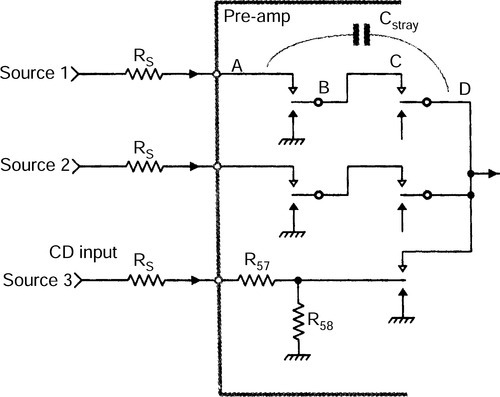
The problem with conventional input select systems like Figure 1(a) is that the various input tracks necessarily come into close proximity, with significant crosstalk through capacitance Cstray to the common side of the switch, i.e. from A to B. Using two changeovers per input side – i.e. four for stereo – allows the intermediate connection B-C to be grounded by the NC contact of the first switch section. This keeps the ‘hot’ input A much further away from the common input line D, as shown in Figure 1(b).

Crosstalk data in Table 1 was gathered at 10 kHz, with 10 kΩ source impedances. The emphasis here is on minimising inter-source crosstalk, as interchannel (L–R) crosstalk is benign by comparison. Interchannel isolation is limited by the placement of left and right on the same switch, with the contact rows parallel, and limits L–R isolation to − 66 dB at 10 kHz with 10 kΩ source impedance.
Table 1
Crosstalk exhibited by four switch arrangements using a 10 kHz test signal
| Simple rotary: | 71 dB |
| Morgan-Jones rotary: | 76 dB |
| 2 c/o switch | 74 dB |
| 4 c/o switch | 95 dB |
With lower source impedances, both intersource and interchannel crosstalk is proportionally reduced. In this case, a more probable 1 kΩ source gives 115 dB of intersource rejection at 10 kHz for the four-pole-changeover method.
Line input criteria
Nowadays the input impedance of a preamp must be high to allow for interfacing to anachronistic valve equipment, whose output may be taken from a valve anode. Even light loading compromises distortion and available output swing. A minimum input impedance is 100 kΩ, which many preamp designs fall well short of.
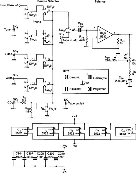
The CD input stands out from other line sources in that its nominal level is usually 1 V rather than 150 mV. This is perfectly reasonable, since digital sources have rigidly defined maximum output levels, and these might as well be high to reduce noise troubles. There is no danger of the analogue output section clipping. However, this means a direct line input cannot be used without the trouble of resetting volume and recording-level controls whenever the CD source is selected.
This problem is addressed here by adding a 16 dB passive attenuator, as shown for Source 3 in Figure 1(b). The assumption is that a CD output has a low impedance, and that a 10 kΩ input impedance will not embarrass it. As a result, resistance values can be kept low to minimise the noise degradation. Output impedance of this attenuator is 1.4kΩ, which generates − 120.9 dBu of Johnson noise as opposed to − 135.2 dBu from a direct 50 Ω source. This is still much less than the preamp internal noise and so the noise floor is not degraded. It is now possible to improve inter-source crosstalk simply by grounding the CD attenuator output when it is not in use, so only a two-pole switch is required for good isolation of this source.
The tape-monitor switch allows the replay signal from the tape deck to be compared with the source signal. With three-head machines, this provides a real-time quality check. But with the much more common two-head appliances, where the input signal is looped straight back to the amplifier in RECORD mode, it only provides confirmation that the signal has actually got there and back.
Line input buffering
This stage has to provide a high input impedance and variable gain for the balance control. My last preamp1 had the balance control incorporated in the tone stage, but this does not appear to be practical with the more complex tone system here.
The vernier balance control alters the relative stage gain by + 4.5, − 1.1 dB – a difference of 6 dB – which is sufficient to swing the image wholly from one side to the other. Since the minimum gain of this noninverting stage is unity, the nominal gain with balance control central is 1.1 dB. Maximum gain of the active gain stage, or AGS, is reduced to allow for this. The active nature of this balance control means that the signal never receives unwanted attenuation that must be undone later with noisy amplification. The gain law is modified by R34 to give as little gain as possible in the centre. Maximum gain is set by R35, Figure 11(b).
A high input impedance is obtained simply by using a high-value biasing resistor R33, accepting that the bias current through this will give some negative output offset; at − 180 mV this is not large enough to reduce headroom. Input impedance is therefore 470 kΩ, high enough to prevent loading problems with any conceivable source equipment.
In discussing noise there are fundamental limits that lend perspective to the process. If the external source impedance is 50 Ω, which is about as low as is plausible, the inherent thermal noise from it is − 135.2 dBu in 22 kHz bandwidth. This is well below the measuring equipment, (AP System 1) which has an input noise floor I measured at − 116.8 dBu, 50 Ω source again.
The noise output of the buffer/balance stage is of the same order and cannot be measured directly – a good way would be to use the flat moving-coil cartridge stage as a preamp for the testgear.2 Calculated noise output is − 116 dBu with balance central.
Controlling tone
I plan to ignore convention once again. I think tone controls are absolutely necessary, and it is a startling situation when, as frequently happens, anxious inquirers to hi-fi advice columns are advised to change their loudspeakers to correct excess or lack of bass or treble. This is an extremely expensive way of avoiding tone controls.
This design is not a conventional Baxandall tone control. The break frequencies are variable over a ten to one range, because this makes the facility infinitely more useful for correcting speaker deficiencies. This enhancement flies in the face of Subjectivist thinking, but I can live with that. Variable boost/cut and frequency enables any error at top or bottom end to be corrected to at least a first approximation. It makes a major difference, as anyone who has used a mixing console with comprehensive EQ will tell you.
Middle controls are quite useless on a preamplifier. They are no good for acoustic correction: after all, even a third-octave graphic equaliser isn’t that much use. Variable frequency mid controls are standard on mixing consoles because their function is voicing – i.e. giving a sound a particular character – rather than correcting response anomalies.
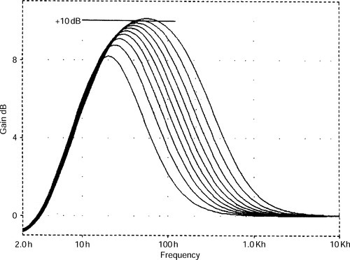
Certain features of the tone control may make it more acceptable to those with doubts about its sonic correctness. The tone control range is restricted to ± 10 dB, rather than the ± 15 dB which is standard in mixing consoles. The response is built entirely from simple 6 dB/octave circuitry, with inherently gentle slopes. The stage is naturally minimum-phase, and so the amplitude curves uniquely define the phase response. This will be shown later, where the maximum phase-shift does not exceed 40° at full boost.
This is a return-to-flat tone control. Its curves do not plateau or shelve at their boosted or cut level, but smoothly return to unity gain outside the audio band. Boosting 10 kHz is one thing, but boosting 200 kHz is quite another, and can lead to some interesting stability problems. The fixed return-to-flat time-constants mean that the boost/cut range is necessarily less at the frequency extremes, where the effect of return-to-flat begins to overlap the variable boost/cut frequencies.
The basic principle is shown in Figure 2. The stage gives a unity-gain inversion, except when the selective response of the side-chain paths allow signal through. In the treble and bass frequency ranges, where the side-chain does pass signal, boost/cut potentiometers VR2,4 can give either gain or attenuation. When a wiper is central, there is a null at the middle of the boost/cut potentiometer, no signal through that side-chain, and gain is unity.
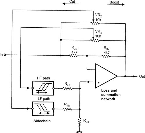
If the potentiometer is set so the side-chain is fed from the input then there is a partial cancellation of the forward signal; if the side-chain is fed from the output then there is a partial negative-feedback cancellation. To put it another way, positive feedback is introduced to counteract part of the negative feedback through R37.
This apparently ramshackle process actually gives boost/cut curves of perfect symmetry. In fact this symmetry is pure cosmetics, because you can’t use both sides of the curve at once, so it hardly matters if they are exact mirror-images.
Bass and treble
The tone control stage acts in separate bands for bass and treble, so there are two parallel selective paths in the side-chain. These are simple RC time-constants, the bass path being a variable-frequency first-order low-pass filter, and the associated bass control only acting on the frequencies this lets through.
Similarly, the treble path is a variable high-pass filter. The filtered signals are summed and returned to the main path via the non-inverting input, and some attenuation must be introduced to limit cut and boost.
Assuming a unity-gain side-chain, this loss is 9 dB if cut and boost are to be limited to ± 10 dB. This is implemented by R43, R48 and R38, Figures 2, 3 and 4. The side-chain is unity-gain, and so has no problems with clipping before the main path does. As a result, it is highly desirable to put the loss after the sidechain, where it attenuates side-chain noise.
The loss attenuator is made up of the lowest value resistors that can be driven without distortion. This minimises both the Johnson noise therein and noise generated by op-amp IC7b.
The tone cancel switch disconnects the entire sidechain, i.e. five out of six op-amps, from any contribution to the main path, and usefully reduces the stage output noise by about 4 dB, depending on the h.f. frequency setting. It leaves only IC7b in circuit, which is required anyway to undo the gain-control phase-inversion.
Unlike configurations where the entire stage is by-passed, the signal does not briefly disappear as the switch moves between two contacts. This minimises transients due to suddenly chopping the waveform and makes valid tone in/out comparisons much easier.
Having all potentiometers identical is very convenient. I have used linear 10 kΩ controls, so the tolerances inherent in a two-slope approximation to a logarithmic law can be eliminated. This only presents problems in the tone stage frequency controls, as linear potentiometers require thoughtful circuit design to give the logarithmic action that fits our perceptual processes.
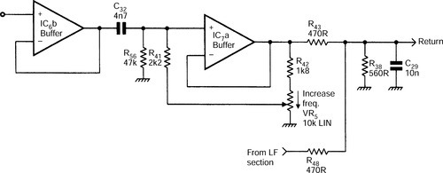
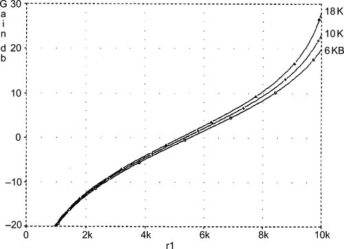
Basics of the treble path are shown in Figure 3. Components C32, R41 are the high-pass time-constant, driven at low-impedance by unity-gain buffer IC6b. This is needed to prevent the frequency from altering with the boost/cut setting. The effective value of R41 is altered over a 10:1 range by varying the amount of boot-strapping it receives-from IC7a, the potential divider effect and the rise in source resistance of VR5 in the centre combining to give a reasonable approximation to a logarithmic frequency/rotation law, Figure 5.

Resistor R42 is the frequency end-stop resistor. It limits the maximum effective value of R41. Capacitor C29 is the treble return-to-flat capacitor. At frequencies above the audio band it shunts all the sidechain signal to ground, preventing the treble control from having any further effect.
The treble side-chain does degrade the noise performance of the tone control stage by 2–3 dB when connected. This is because it must be able to make a contribution at the h.f. end of the audio band. As you would expect, the noise contribution is greatest when the h.f. frequency is set to minimum, and so a wider bandwidth from the side-chain contributes to the main path.
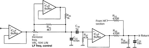
The simplified bass path is shown in Figure 4. Op-amp IC6a buffers VR2 to prevent boost/frequency interaction. The low-pass time-constant capacitor is C37, and the resistance is a combination of VR3 and R45,46.
Capacitors C38,39 with R47 make up the return-to-flat time-constant for the bass path, which blocks very low frequencies, limiting the lower extent of bass control action. The bass frequency law is made approximately logarithmic by IC8b; for minimum frequency VR3 is set fully counter-clockwise, so the input of buffer IC8b is the same as the C37 end of R46, which is thus bootstrapped and has no effect.
Turnover
When VR3 is fully clockwise, R45,46 are effectively in parallel with VR3 and the turnover frequency is at a maximum. Resistor R45 provides some extra law-bending, Figure 6. Sadly, an extra op-amp is required. However, despite its three op-amps, the bass side-chain contributes very little extra noise to the tone stage. This is because most of its output is inherently rolled off by the low-pass action of C37 at high frequencies, almost eliminating its noise contribution.
Once the active elements have been chosen – here 5532 s – and the architecture made sensible in terms of avoiding attenuation-then-amplification, keeping noise-gain to a minimum, and so on, there remains one further means of improving noise performance. This is to reduce the impedance of the circuitry.
The resistances are lowered in value, with capacitances scaled up to suit, by a factor that is limited only by op-amp drive capability. This is another good reason to use the 5534/2.
Two examples of this process as applied to the tone stage are given here. In each case the noise improvement is for the stage in isolation, set flat with high frequency set at minimum:
Firstly, in this sort of stage R36,37 are conventionally 22 kΩ. This was reduced to 4.7kΩ, and noise output dropped by 1.3 dB. Second, the summation/loss network began with R43,48 as 4.7kΩ, and R38 as 5.6kΩ. Reducing this by a factor of ten to 470 Ω and 560 Ω respectively reduced output noise by 0.6 dB.
With balance control central and tone cancel pressed, noise output of the tone stage, plus the line/balance buffer before it is − 107.2 dBu. This is 22 kHz bandwidth. With tone controls active but set flat, noise output at minimum high frequency is − 104.7 dBu, and at maximum is − 106.7 dBu.
The final tone stage may look rather a mess of pottage, and be afflicted with more buffers than Clapham Junction. This is unavoidable if control interaction is to be wholly eliminated. Sadly, the practical tone circuit is somewhat more complex than Figures 2, 3 and 4, reflecting one of the disadvantages of low-noise opamps. This is that bipolar input stages mean that the bias currents are non-negligible. They must not be allowed to flow through potentiometers if crackling noises are to be avoided when they are moved.
These bias currents also tend to be reflected in significant output offset voltages, as the source resistances for the two op-amp inputs are not normally the same. All gain-variable circuit stages therefore have their gain reduced to unity at d.c. This subject is detailed later.
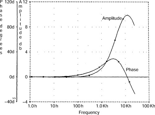
Figure 7 shows the measured extremes of cut and boost at the frequency extremes. Figure 8 gives the phase-shift at h.f. while Figure 9 shows phase-shift at low frequencies. In both cases it is very modest.


Active gain stage
The active gain stage, or AGS, used here as in,1 is due to Baxandall.3 Maximum gain is set to + 23 dB by the ratio of R52,53, to amplify a 150 mV line input to 2 V with a small safety margin.
An active volume-control stage gives the usual advantages of lower noise at gain settings below maximum, and for the Baxandall configuration, excellent channel balance that depends solely on the mechanical alignment of the dual linear potentiometer. All mismatches of its electrical characteristics are cancelled out, and there are no quasi-log dual slopes to induce anxiety.
Note that all the potentiometers are 10 kΩ linear types and identical, apart from the question of centre-detents, which are desirable only on the balance, treble and bass boost/cut controls.
Compared with,1 noise has been reduced by an impedance reduction on the gain-definition network R52,53. The limit on this is the ability of buffer IC5a to drive R52, which has a virtual earth at its other end. Figure 10 shows the volume control law for different maximum gain settings; only the very top end of the curve alters significantly.
For the rear section of the preamp – i.e. that shown in Figure 11(a) – the noise performance depends on control settings. The below gives results for h.f. frequency at minimum, the worst case, Table 2.
Table 2
Characteristics of the tone-control stage
| Tone cancel (dBu) | Tone flat (dBu) | |
| AGS zero gain | − 114.5 | − 114.5 |
| AGS unity gain | − 107.4 | − 105.3 |
| AGS fully up | − 90.2 | − 86.4 |
The figures for maximum gain may look unimpressive, but remember this is with + 23 dB of gain; at normal volume settings the noise output is below − 100 dBu. I think this is reasonably quiet.
Output muting and relay control
The preamp includes relay muting on the main outputs. This is to prevent thuds and bangs from upstream parts of the audio system from reaching the power amplifiers and speakers at power-up and power down. Most op-amp circuitry, being dual-rail (i.e. outputs at 0 V) does not inherently generate enormous thumps, but it cannot be guaranteed to be completely silent. It may produce a very audible turn-on thud, and often objectionable turn-off noise. I recall one design that emitted an unnerving screech of fading protest as the rails subsided.…
Electronic muting is desirable, but introduces unacceptable compromises in performance. Relay muting, given careful relay selection and control, is virtually foolproof. The relay must be normally-open so the output is passively muted when no power is applied. The control system must:
• Delay relay pull-in at power-up, to mute turn-on transients. A delay of at least 1 second before the relay closes.
• Drop out the relays as fast as possible at power-down, to stop the dying moans of the preamp, etc., from being audible.
My preferred technique is a 2 ms or there-abouts power-gone timer, held in reset by the a.c. on the mains transformer secondary, except for a brief period around the a.c. zero-crossing, too short to allow the timer to trigger. When the a.c. disappears, this near-continuous reset is removed, the timer fires, and relay power is removed within 2 ms. This is over long before the reservoir capacitors in the system can discharge, so turn-off transients are authoritatively suppressed.
However, if the mains switch contacts generate an r.f. burst that is in turn reproduced as a click by the preamplifier, then even this method may not be fast enough to completely mute it.
Figure 11(b) shows the practical relay-control circuit. At turn-on, R211 slowly charges C224 until Tr205 and D207 are forward biased, i.e. when C224 voltage exceeds that set up by R214,215. This is the turn-on delay. Transistor Tr206 is then turned on via R213, energising the relays, and LD201 is brightly lit through D208 and R216. This led is dimly lit via R217 as soon as power is applied, but only brightens when the initial mute period is over.
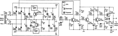
As long as mains power is applied, Tr203 is kept turned on through D205,206 by the a.c. ahead of the bridge rectifier, except during the zero-crossing period every 10 ms, when the voltage is too low for Tr203 base to conduct. When Tr203 switches off, C223 starts to charge through R208, but is quickly discharged through R207 when the very brief zero-crossing period ends. If it does not end – in other words mains power has been switched off – C223 keeps charging until Tr204 turns on, discharging C224 rapidly via R210, and removing power from the relays almost instantly.
DC blocking and additional details
The preamp circuitry has been described as each stage was dealt with, so this section is confined to d.c. blocking problems and other odd subjects.
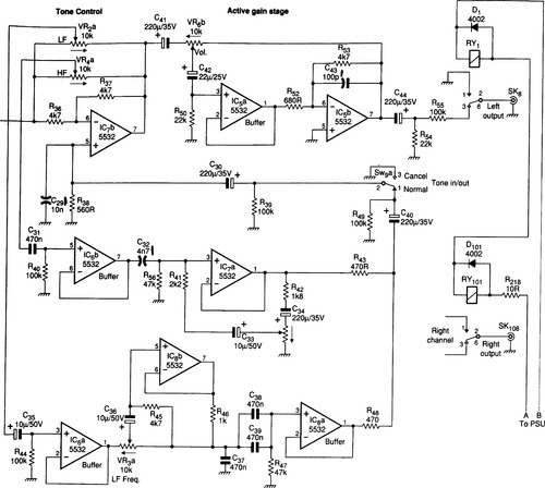
The complete circuit of the line section of the preamp is Figure 11(a). Bias current is kept out of balance potentiometer VR1 by C27, and d.c. gain held to unity by C28. Capacitors C31 and C35 keep bias currents out of VR2,4, necessitating bias resistors R40,R44.
The treble frequency law is corrected by bootstrapping through C33, which keeps the bias current of IC7a out of VR5. Similarly, C34 prevents any offset on IC7a output reaching VR5. In the bass path C36 keeps IC8b bias out of VR3, while return-to-flat components C38,39 and R47 provide inherent d.c.-blocking.
Final offsets at the side-chain output are blocked by C40, while IC7b bias is blocked by C30. This is essential to prevent the tone-cancel switch clicking due to d.c. potentials. Bear in mind that this switch may still appear to click if it switches in or out a large amount of response-modification of a non-zero signal. This is because the abrupt gain-change generates a step in the waveform that is heard as a click. This is unavoidable with hard audio switching.
Capacitor C41 keeps IC7b output offset from volume control VR6, while C42 blocks IC5a bias current from the pot wiper. Capacitor C44 gives final d.c.-blocking to protect the following power amplifier.
Many components in this design are the same value; for example, wherever a sizable non-electrolytic is required, 470 nF could usually be made to work. This philosophy has to be abandoned in areas where critical parameters are set, such as the RIAA network and tone control stage.
Supplying power
This is a conventional power supply using IC regulators. I strongly recommend that you use a toroidal mains transformer to minimise the a.c. magnetic field.
Supply rails have been increased from ± 15 to ± 18 V to maximise headroom. Nonetheless, 15 V regulators are specified as they are easy to obtain. Their output increased to 18 V by means of R201,203, Tr201 and R202,204, Tr202.
It is common to use a potential divider to ‘stand-off’ the regulator by a fixed proportion of the output voltage. In the improved version here, positive divider R201,203 is buffered by emitter-follower Q201. Thus R201,203 can be higher in value – saving power – while Tr201 absorbs the ill-defined quiescent current from the regulator COM pin.
Choosing the right op-amps
Exotic and expensive op-amps will probably give a disappointing noise performance. The bipolar input of the 5534/32 is well matched to the medium-low impedances used in this preamplifier. For example, an OP-27 might be expected to be quieter in the moving-magnet cartridge stage; but when measured, or calculated, it is 2 dB noisier.
The performance
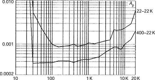
Figure 12 shows the THD of the flat moving-coil cartridge stage alone, at maximum gain. The rise at extreme if is due to the integrator time-constant. Figures 13 and 14 give the THD of the moving-magnet cartridge disc input and the entire rear section respectively. Levels involved are ten times those found in real use. Distortion is not a problem here.


Crosstalk performance attained depends very much on physical layout. Capacitive crosstalk can be minimised by spacing components well apart, or by simple screening. Resistive crosstalk depends on the thickness of the various ground paths.
It would be desirable to specify a grounding topology for optimal results, but this is not so easy. I found that the more tightly the various grounds are tied together with heavy conductors, the better the crosstalk performance. There seemed little scope for subtlety.
As with noise performance, the results depend somewhat on control settings, but under most conditions the prototype gave about − 100 dB flat across 20 Hz–20 kHz, with noise contributing to the reading. This was not hard to achieve.
The preamplifier in perspective
In determining what (if anything) has been achieved by this design, we must see if it is capable of any further improvement.
• The moving-magnet stage input noise performance is limited by the electrical characteristics of the cartridge and its loading needs.
• Making the RIAA any more accurate will be expensive.
• Increasing disc input headroom would require the use of higher supply rails, demanding discrete amplifier stages.
Having gone to some effort to make the preamplifier as noise-free and transparent as possible, we should ask how it compares with other parts of the system. The standard Blameless Class B power amplifier4 output noise is − 93.5 dBu, and the Trimodal5 with the low-impedance feedback network reduces this to − 95.4 dBu. In both cases the source impedance is 50 Ω.
Both amplifiers have a closed-loop gain of + 27.2 dB, and so the equivalent input noise (EIN) is − 120.7 and − 122.6 dBu respectively. This can be compared with the source-resistance Johnson noise of 50 Ω, which is − 135.2 dBu. The best power-amp noise figure is therefore 12.6 dB, which is some way short of perfection.
In contrast, the noise output from the preamplifier is never less than − 114.5 dBu with the volume control at zero. Even in this rather useless condition, the preamplifier increases the total noise output, as it produces 8 dB more than the Trimodal power amplifier input noise. At mid-volume (in-line mode) the preamplifier noise is − 105.3 dBu, which is 17 dB worse than the power-amp; clearly as far as preamp design is concerned, history has not yet ended.
Even so, serious thought has been given to whether this may be the quietest preamp yet built. Comments and opinions on this are invited.