
Precision preamplifier
By the time the Precision Preamplifier of 1983 was conceived, the remarkable 5534/5532 op-amps were available at a reasonable price, and delivered very low noise with almost unmeasurable distortion, given a few simple precautions. It became clear that even if ultimate performance was the goal, it was no longer economical or sensible to assemble eight or more transistors into a home-made discrete op-amp. The adoption of op-amps meant a return to dual regulated power supplies, but time and progress had made this option less costly than it had been when the Advanced Preamplifier was designed.
I put a lot of effort into producing the best design I could, taking the ‘precision’ bit very seriously. I found that getting the RIAA equalization accurate beyond a certain point by cut-and-try methods was virtually impossible, and very quickly exhausted my limited supplies of patience, so I fired up the BBC Model-B (computers only took a second or so to boot in those days – we have come a long way since then) and wrote some software to optimize the RIAA component selection, evaluated dozens of different volume-control laws, and minimised noise at every point; it was very well received, so it was worth it. As with several of the designs described here, I still use the prototype on a regular basis.
Until relatively recently, any audio preamplifier with pretensions to above-average quality had to be built from discrete transistors rather than integrated circuits. The 741 series of op-amps was out of the question for serious audio design, due to slew-rate and other problems, and the TL071/72 types, though in many ways excellent, were still significantly noisier than discrete circuitry. In an article some years ago,1 I attempted to show that it was still feasible to better the performance of such devices by using simple two or three-transistor configurations.
The appearance of the 5534 low-noise op-amp at a reasonable price, has changed this. It is now difficult or impossible to design a discrete stage that has the performance of the 5534 without quite unacceptable complexity. The major exception to this statement is the design of low-impedance low-noise stages such as electronically-balanced microphone inputs or moving-coil head amplifiers, where special devices are used at the input end.
5534 op-amps are now available from several sources, in a conventional 8-pin d.i.l. format. This version is internally compensated for gains of three or more, but requires a small external capacitor (5–15 pF) for unity-gain stability. The 5532 is a very convenient package of two 5534 s in one 8-pin device with internal unity-gain compensation, as there are no spare pins.
The 5534/2 is a low-distortion, low-noise device, and a typical audio stage could be expected to generate less than 0.005% THD over the range 1–20 kHz, leaving the residual distortion lost in the noise of all but the most expensive analysers. Noise performance obviously depends partly on external factors, such as source resistance and measurement bandwidth, but as an example consider the moving-magnet disc input stage shown in Figure 3. When prototyped with a TL071, the noise (with a 1 k resistor input load) was − 69 dB with reference to a 5 mV r.m.s. 1 kHz input. Substituting a 5534 improved this to − 84 dB, a clear superiority of 15 dB.


Another advantage of this device to the audio designer is its ability to drive low-impedance loads (down to 500 Ω in practice) to a full voltage swing, while maintaining low distortion. This property is much appreciated by studio mixer designers, whose output amplifiers are still expected to drive largely fictitious 600 Ω loads. As a comparison, the TL071 is only good for loads down to about 2 kΩ.
Architecture
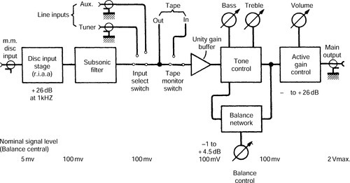
As explained in a previous article,1 the most difficult compromise in preamplifier design is the distribution of the required gain (usually at least 40 dB) before and after the volume control. The more gain before the volume control, the lower the headroom available to handle unexpectedly large signals. The more gain after, the more the noise performance deteriorates at low volume settings. Another constraint is that it is desirable to get the signal level up to about 100 mV r.m.s. before reaching the volume control, as tape inputs and outputs must be placed before this. The only really practical way to get the best of both worlds is to use an active gain-control stage – an amplifier that can be smoothly varied in gain from effectively zero up to the required maximum.
If the input to the disc stage is a nominal 5 mV r.m.s. (assumed to be at 1 kHz throughout the avoid confusion due to RIAA equalization) from either moving-magnet cartridge or moving-coil head amp, then 26 dB of gain will be needed to give the 100 mV which is the minimum it is desirable to offer as a tape output. This can easily be got from a single 5534 stage, and taken together with the supply rails (± 15 V) this immediately fixes the disc input overload at about 320 mV r.m.s. A figure such as this is quite adequate, and surpasses most commercial equipment.
One must next decide how large an output is needed at maximum volume for the 5 mV nominal input. 1 V r.m.s. is usually ample, but to be certain of being able to drive exotic units to their limits, 2 V r.m.s. is safer. This decision is made easier because using an active gain-control frees us from the fear of having excessive gain permanently amplifying its own noise after the volume control. Raising the 100 mV to this level requires the active gain stage to have another 26 dB of gain available; see the block diagram in Figure 1.
The final step in fixing the preamp, architecture is to place the tone-control in the optimum position in the chain. Like most Baxandall stages, this requires a low-impedance drive if the response curves are to be predictable, and so placing it after the active gain-control block (which has the usual very low output impedance) looks superficially attractive. However, further examination shows that (a) the active-gain stage also requires a low-impedance drive, so we are not saving a buffer stage after all, and (b) since it uses shunt feedback the tone-control stage is rather noisier than the others,2 and should therefore be placed before the gain control so that its noise can be attenuated along with the signal at normal volume settings. The tone-control is preceded by a unity-gain buffer stage with low output impedance and a very high input impedance, so that the load placed on line input devices does not vary significantly when the tape-monitor switch is operated. This brings us to the block diagram in Figure 1. Figure 3 shows the circuit diagram of the complete preamplifier. The components around A1 and A2 make up the moving-magnet disc stage and its associated subsonic filter. Disc preamplifier stage A1 uses a quite conventional series feedback arrangement to define the gain and provide RIAA equalisation. This provides a clear noise-performance advantage of 13 dB over the shunt feedback equivalent,2,3 which is sometimes advocated on the rather dubious grounds of ‘improved transient response’. The reality behind this rather woolly phrase is that the series configuration cannot give the continuously descending frequency response in the ultrasonic region that the RIAA specification seems to imply, because its minimum gain is unity. Hence sooner or later, as the frequency increases, the gain levels out at unity instead of dropping down towards zero at 6 dB per octave. As described in Refs. 1 and 2, when a low-gain input stage is used to obtain a high overload margin, ‘sooner’ means within the audio band, and so an additional low-pass time-constant is required to cancel out the unwanted h.f. breakpoint; once more it is necessary to point out that if the low-pass time-constant is correctly chosen, no extra phase or amplitude errors are introduced. This function is performed in Figure 3 by R8 and C11, which also filter out unwanted ultrasonic rubbish from the cartridge.
It was intended from the outset to make the RIAA network as accurate as possible, but since the measuring system used (Sound Technology 1700 A) has a nominal accuracy of 0.1 dB, 0.2 dB is probably the best that could be hoped for. Designing RIAA networks to this order of accuracy is not a trivial task with this configuration, due to interaction between the time-constants, and attempting it empirically proved most unrewarding. However, Lipshitz, in an exhaustive analysis of the problem, using heroic algebra in quantities not often seen, gives exact but complicated design equations.4 These should not be confused with the rule- of-thumb time-constants often quoted. The Lipshitz equations were manipulated on an Acorn Atom microcomputer until the desired values emerged. These proved on measurement to be within the 0.2 dB criterion, with such errors as existed being ascribable to component tolerances.
Design aims were that the gain at 1 kHz should be 26 dB, and that the value of R3 should be as small as feasible to minimize its noise contribution. These two factors mean that the RIAA network has a lower impedance than usual, and here the load-driving ability of the 5534 is helpful in allowing a full output voltage swing, and hence a good overload margin.
There is a good reason why the RIAA capacitors are made up of several in parallel, when it appears that two larger ones would allow a close approach to the correct value. It is pointless to design an accurate RIAA network if the close-tolerance capacitors cannot be easily obtained, and in general they cannot. The exception to this is the well-known Suflex range, usually sold at 2.5% tolerance. These are cheap and easy to get, the only snag being that 10 nF seems to be the largest value widely available, and so some paralleling is required. This is however a good deal cheaper and easier than any other way of obtaining the desired close-tolerance capacitance.
Metal-oxide resistors are used in the RIAA network and in some other critical places. This is purely to make use of their tight tolerance (1% or 2%), as tests proved, rather unexpectedly, that there was no detectable noise advantage in using them.
The recently updated RIAA specification includes what is known as the ‘IEC amendment’. This adds a further 6 dB/octave low-cut time-constant that is − 3 dB at 20.02 Hz. It is intended to provide some discrimination against subsonic rumbles originating from record warps, etc., and in a design such as this, with a proper subsonic filter, it is rather redundant. Nonetheless the time-constant has been included, in order to keep the bottom octave of the RIAA accurate. The time-constant is not provided by R3 C3 (which is no doubt what the IEC intended) but by the subsonic filter itself, a rather over-damped third-order Butterworth type designed so that its slow initial roll-off simulates the 20.02 Hz time-constant, while below 16 Hz the reponse drops very rapidly. Implementing the IEC roll-off by reducing C3 is not good enough for an accurate design due to the large tolerances of electrolytic capacitors. However, the R3, C3 combination is arranged to roll-off lower down (− 3 dB at about 5 Hz) to give additional subsonic attenuation.
Capacitor C1 defines the input capacitance and provides some r.f. rejection. A compromise value was chosen, and this may be freely modified to suit particular cartridges.
The noise produced by the disc input stage alone, with its input terminated with a 1 k resistor to simulate roughly a moving-magnet cartridge, is − 84.5 dB with reference to a 5 mV r.m.s. 1 kHz input (i.e. 100 mV r.m.s. out) for a typical 5534 A sample. The suffix A denotes selection for low noise by the manufacturer. When the 1 k termination is replaced by a short circuit, the level drops to − 86 dB, indicating that in real life the Johnson noise generated by the cartridge resistance is significant, and so that stage is really as quiet as it is sensible to make it.
Subsonic filter
As described above, this stage not only rejects the subsonic garbage that is produced in copious amounts by even the flattest disc, but also implements the IEC roll-off. Below 16 Hz the slope increases rapidly, the attenuation typically increasing by 10 dB before 10 Hz is reached. The filter therefore gives good protection against subsonic rumbles, that tend to peak in the 4–5 Hz region.
This filter obviously affects the RIAA accuracy of the lowest octave, and so C12, C13, C14 should be good-quality components. A 10% tolerance should in practice give a deviation at 20 Hz that does not exceed 0.7 dB, rapidly reducing to an insignificant level at higher frequencies. The tape output is taken from the subsonic filter, with R12 ensuring that long capacitative cables do not cause h.f. instability. If it really is desirable to drive a 600 Ω load, then C15 must be increased to 220 μF to maintain the base response.
High-impedance buffer
This buffer stage is required because the following tone-control stage demands a low-impedance drive, to ensure that operating the tape monitor switch S2 does not affect the tape-output level. If the input selector switch S1 was set to accept an input from a medium impedance source (say 5 k), and the buffer had a relatively low input impedance (say 15 k), then every time the tape-monitor switch was operated there would be a step change in level due to the change of loading on the source. This is avoided in this design by making the buffer input impedance very high by conventional bootstrapping of R15, R16 via C17. This is so effective that the input impedance is defined only by R14. Unlike discrete-transistor equivalents, this stage retains its good distortion performance even when fed from a high source resistance, e.g. 100 k.
Tone-control stage
Purists may throw up their hands in horror at the inclusion of this, but it remains a very useful facility to have. The range of action is restricted to ± 8 dB at 10 kHz and ± 9 dB at 50 Hz, anything greater being out of the realm of hi-fi. The stage is based on the conventional Baxandall network with two slight differences. Firstly the network operates at a lower impedance level than is usual, to keep the noise as low as possible. The common values of 100 k for the bass control and 22 k for the treble control give a noise figure about 2.5 dB worse. Even with the values shown, the tone stage is about 6 dB noisier than the buffer that precedes it. Both potentiometers are 10 k linear, which allows all the preamplifier controls to be the same value, making getting them a little easier. The low network impedance also reduces the likelihood of capacitative interchannel crosstalk. Once again, implementing it is only possible because of the 5534’s ability to drive low-value loads.
Secondly, the tone-control stage incorporates a vernier balance facility. This is also designed as an active gain-control, with the same benefit of avoiding even small compromises on noise and headroom. The balance control works by varying the amount of negative feedback to the Baxandall network, and therefore some careful design is needed to ensure that the source resistance of the balance section remains substantially constant as the control is altered, or the frequency response may become uneven. Resistors R22, R23, R24 define this source resistance as 1 k, which is cancelled out by R17 on the input side. The balance control has a range of + 4.5 to − 1.0 dB on each channel, which is more than enough to swing the stereo image completely from side to side. If you need a greater range than this, perhaps you should consider siting your speakers properly.
Active gain-control stage
An active gain-control stage must fulfil several requirements. Firstly, the gain must be smoothly variable from maximum down to effectively zero. Secondly, the law relating control rotation and gain should be a reasonable approximation to logarithmic, for ease of use. Finally, the use of an active stage allows various methods to be used to obtain a better stereo channel balance than the usual log. pot. offers.
All the configurations shown in Figure 2 meet the first condition, and to a large extent, the second. Figures 2(a) and 2(b) use linear controls and generate a quasi-logarithmic law by varying both the input and feedback arms of a shunt-feedback stage. The arrangement of Figure 2(c), as used in the previous article, offers simplicity but relies entirely on the accuracy of a log. pot. While 2(a) and 2(b) avoid the tolerances inherent in the fabrication of a log. track, they also have imperfect tracking of gain, as the maximum gain in each case is fixed by the ratio of a fixed resistor Rm to the control track resistance, which is not usually tightly controlled. This leads to imbalance at high gain settings.
Peter Baxandall solved the problem very elegantly,1 by the configuration in 2(d). Here the maximum gain of the stage is set not by a fixed-resistor/track-resistance ratio, but by the ratio of the two fixed resistors Ra, Rb. A buffer is required to drive Ra from the pot. wiper, because in a practical circuit this tends to have a low value. It can be readily shown by simple algebra that the control track resistance now has no effect on the gain law, and hence the channel balance of such a system depends only on the mechanical alignment of the two halves of a dual linear pot. The resulting gain law is shown in Figure 4, where it can be seen that a good approximation to the ideal log (i.e. linear in dB) law exists over the central and most used part of the control range.

A practical version of this is shown in Figure 3. A5 is a unity-gain buffer biased via R25, and R26, R27 set the maximum gain to the desired + 26 dB. Capacitor C25 ensures h.f. stability, and the output capacitor C26 is chosen to allow 600 Ω loads to be driven. A number of outwardly identical Radiohm 20 mm dual-gang linear pots were tested in the volume control position, and it was found that channel balance was almost always within ± 0.3 dB over the gain range − 20 to + 26 dB, with occasional excursions to 0.6 dB. In short, this is a good way of wringing the maximum performance from inexpensive controls, and all credit must go to Mr Baxandall for the concept.
At the time of writing there is no consensus as to whether the absolute polarity of the audio signal is subjectively important. In case it is, all the preamplifier inputs and outputs are in phase, as the inversion in the tone stage is reversed again by the active-gain stage.
Power supply
The power supply is completely conventional, using complementary i.c. regulators to provide ± 15 V. Since the total current drain (both channels) is less than 50 mA, they only require small heatsinks. A toriodal mains transformer is recommended for its low external field, but it should still be placed as far as possible from the disc input end of the preamplifier. Distance is cheaper (and usually more effective) than Mu-Metal. Since the 5534 is rated up to ± 20 V supplies, it would be feasible to use ± 18 V to get the last drop of extra headroom. In my view, however, the headroom already available is ample.
Construction
The preamplifier may be built using either 5534 op-amps or the 5532 dual type. The latter are more convenient (requiring no external compensation) and usually cheaper per op-amp, but can be difficult to obtain. To compensate each 5534 for unit gain, necessary for each one, connect 15 pF between pins 5 and 8. Note that the rail decoupling capacitors should be placed as close as possible to the op-amp packages – this is one case in which it really does matter, as otherwise this i.c. type is prone to h.f. oscillation that is not visible on a scope, but which results in a very poor distortion performance. It must also be borne in mind that both the 5534 and 5532 have their inputs tied together with back-to-back parallel diodes, presumably for voltage protection, and this can make fault-finding with a voltmeter very confusing.
Only 2.5% capacitors should be used in the RIAA networks if the specified accuracy is to be obtained. Resistors in Figure 3 marked * should be metal oxide 1% or 2%, for reasons of tolerance only. Each of these resistors sets a critical parameter, such as RIAA equalization or channel balance, and no improvement, audible or otherwise, will result from using metal oxide in other positions.
Several preamplifier prototypes were built on Veroboard, the two channels in separate but parallel sections. The ground was run through in a straight line from input to output. Initially the controls were connected with unscreened wire, and even this gave acceptable crosstalk figures of about − 80 dB at 10 kHz, due to the low circuit impedances. Screening the balance and volume connections improved this to − 90 dB at 10 kHz, which was considered adequate. It must be appreciated that the crosstalk performance depends almost entirely on keeping the two channels physically separated.
Some enthusiasts will be anxious to (a) use gold-plated connectors; (b) by-pass all electrolytics with non-polarized types; or (c) remove all coupling capacitors altogether, in the pursuit of an undefinable musicality. Options (a) and (b) are pointless and expensive, and (c) while cheap, may be dangerous to the health of your loudspeakers. Anyone wishing to dispute these points should arm themselves with objective evidence and a stamped, addressed envelope.