
04
BIM Adoption and Maturity Levels

Introduction
The Department for Business Innovation and Skills (BIS) formed a Working Party in 2010 to advise the government as the construction client on national policy for the transitioning to BIM. The Working Party’s BIM Strategy Paper presented the technology adoption as maturing through distinct phases, called BIM Maturity Levels. This chapter explains these levels in the practical terms of the main collaborative processes of each for an organisation. It concludes with a section on setting goals and objectives for BIM adoption.
The key coverage of this chapter is as follows;
- What does BIM maturity look like?
- Goal setting for design and construction collaboration in BIM
What does BIM Maturity Look Like?
Levels of Data Integration and Collaborative Working
The diagram on the facing page is attributed to Mervyn Richards and Mark Bew, both key architects of the Government BIM Strategy.
The slope represents the adoption of BIM as a trajectory of increasing collaboration through better integration of project data with computer-based graphics elements.
| 0 | Unmanaged CAD, probably 2D, with paper (or electronic paper) as the most likely data exchange mechanism. |
| 1 | Managed CAD in 2D or 3D format using BS1192:2007 with a collaboration tool providing a common data environment, possibly some standard data structures and formats. Commercial data managed by standalone finance and cost management packages with no integration. |
| 2 | Managed 3D environment held in separate discipline ‘BIM’ tools with attached data. Commercial data managed by an ERP. Integration on the basis of proprietary interfaces or bespoke middleware could be regarded as ‘pBIM’ (proprietary). The approach may use 4D programme data and 5D cost elements as well as feed operational systems. |
| 3 | Fully open process and data integration enabled by ‘web services’ compliant with emerging IFC / IFD standards, managed by a collaborative model server. Could be regarded as iBIM or ‘integrated BIM’, potentially employing concurrent engineering processes. |
The maturity of this integration falls into distinct phases, or levels. These range from uncoordinated 2D drawing production using CAD (Level 0) to project and asset data mapped to elements in searchable integrated web-based 3D building models (Level 3)
In the BIM Working Party’s Strategy Paper2 (commissioned by the UK Department for Business Innovation and Skills), the BIM Maturity Levels as defined as shown on the facing page.
Working at Level 0
BIM Level 0 means that, although drawings are prepared in an editable CAD format, the exchange of project data is largely paper-based. This level includes the exchange of electronic paper formats, such as PDF. While these formats are readable, they are not particularly reusable for drafting purposes.
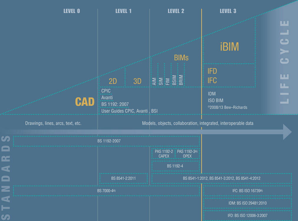
Figure 4.1
The Bew-Richards BIM maturity diagram1
One key capability of CAD is that it allows users to organise drawing elements into distinct layers. This feature gives control over the presentation and visibility of different groups of elements.
The British Standard for coordinating project information in CAD, BS-1192:2007,3 provides detailed guidance on how layers should be implemented to manage the exchange of drawing information. Nevertheless, if a design practice uses CAD systems to prepare its drawings, but doesn’t exchange those files with other project members in accordance with a common layer naming convention, they are still operating at BIM Level 0.
In its introduction, BS-1192 mentions the challenges associated with unmanaged CAD: ‘Each year considerable resources are spent on making corrections to non-standard data, training new personnel in approved data creation techniques, coordinating the efforts of subcontractor teams and solving problems related to data reproduction.’
This observation must resonate with those practices experiencing frustration with incompatible CAD file formats and inconsistent layer and file naming.
What is Level 1?
In order to address these challenges, the focus of moving from Level 0 to Level 1 is on applying a regime of standardised processes for sequentially naming, distributing and combining the distinct 2D and 3D CAD contributions of each project participant in an organised and efficient manner. The focus at Level 1 is on the production of coordinated drawings, and not on the use of any information that might be embedded or linked to them.
For BIM Level 1, the architect will initiate the project team’s file-based drawing exchange process by the first issue. Typically, this would be via an online file storage portal configured for the project. An automatic notification of the upload would be issued through this portal to other participants.
The team of consultants will download, but not modify, each other’s drawings. Instead, they use a key capability of CAD that allows them to utilise each discipline’s drawing files as a background to their own drawings (in CAD terminology, these backgrounds are variously known as external references, or reference files).
For BIM Level 1, the project team work with a common layer structure to organise all of the drawn information that they exchange through CAD. For instance, in accordance with BS-1192, the architectural elements would be placed on layers with names prefixed by ‘A’. Similarly, the structural engineer’s components would be assigned to a set of layers beginning with ‘S’. Beam elements would be distinguished from columns by placing them on a different layer. The process of assigning elements to various layers may even be automated by sophisticated programming routines.
At BIM Level 1, the naming convention is extended to other elements, such as folders and files. The conscientious organisation of drawings into consistently named layers, files and folders provides a ready means of searching, isolating and coordinating the various elements from each discipline.
In order to maintain consistent positioning, it is important for all drawings to share a common reference location, i.e. origin, and for them to be oriented by the same angle relative to true North. Once agreed, this shared positioning ensures that drawings can be inserted into each other without the time-consuming effort of having to adjust them repeatedly.
Central to Level 1 maturity is the establishment of a Common Data Environment. This is the collaboration tool that BS-1192 describes as ‘a repository, for example a project extranet or electronic document management system’ which will ‘allow information to be shared between all members of the project team’. Its key capabilities are described further in Chapter 8.
What is Level 2?
BIM Level 2 builds upon Level 1 and represents the next development in multi-disciplinary design/construction data integration.

Figure 4.2
BIM Level 2: Collaboration using a federated model4
For BIM Level 2:
- The BIM software used to create each model can be specific to each discipline. For example, the architects might use Graphisoft ArchiCAD®, while structural engineers develop the beams, columns, braces and their connections in Revit Structure®. At the same time, the building services engineers might opt for AutoCAD MEP®. Although the client, lead designer or main contractor might still demand native models, there is no imperative in the British Standards documentation for the project team to exchange them in that format. Project team members are not obliged to use the same core software application in order to create their models; instead, typically, the tools that they use to produce and update their own model files are those best suited to their respective specialties.
- The BIM Level 2 definition given in Table 4.1 refers to ‘proprietary interfaces or bespoke middleware’. These terms describe another software package that acts as a bridge by combining models that might otherwise be incompatible – a process known as model federation. In layman’s terms, agreeing on this proprietary interface means that, while the project team are free to use a variety of applications for generating models, all of them must be capable of being exported to a common format that allows them to be combined by means of the software ‘bridge’.
Examples of programs that can combine models which vary in native file format include Autodesk Navisworks®, Bentley Project Navigator®, Tekla BIMSight® and Solibri Model Checker®.
Since these files will be merged into a federated model, they should be exported in a format that preserves their original geometry, the model’s location in 3D space and links to any associated data. In the British Standard PAS-1192-2, these exported files are called model renditions.
- Commercial data can be managed by an enterprise resource planning system (ERP)’. ERP systems are the major applications that integrate information-based processes across the many functional departments of a large business, such as those of a main contractor.

Figure 4.3 The underlying BIM database revealed by exporting a Revit model to Microsoft Access
In comparison with CAD geometry, BIM elements contain significantly more properties to which end-users can add data. So, as the building services engineer inserts a plumbing fixture into the model, he or she can also specify its manufacturer, model number, colour, material and catalogue code.
When stored in BIM, this information is database-compatible. (see fig. 4.3) As indicated by the use of the term ‘can be managed’ above, this data can be integrated and updated using ERP, the enterprise-wide information systems that connect various other business departments, such as planning, manufacturing, sales, marketing, distribution, accounting, human resources, project management, inventory control, and maintenance. This is because, at its heart, BIM is the graphical front end to a database.
Accordingly, if this data represents a level of information that is considered definitive (see Chapter 9), it can be extracted from the model and issued by the contractor to those responsible for procuring construction items and materials.
The challenges of moving to BIM Level 2
The transition to BIM Level 2 is characterised by working in an integrated model environment in order to improve and resolve 3D coordination issues. One of the biggest challenges for the BIM Manager is to encourage the senior project decision-makers responsible for coordination to move from working solely in 2D into the newer and less familiar environment of 3D elements and models.
It should be remembered that this transition to 3D will never signify a complete end to 2D drawing review. Nevertheless, it is a waste of the considerable investment in BIM if some staff members (more often than not the ‘old hands’) restrict themselves to working in 2D; moreover, this would lead to a situation in which their interaction with the model would remain forever mediated by eager young technicians who are willing to ‘chauffeur’ them around it. This is certainly not what is intended by BIM level 2; a lack of 3D design review competence among senior designers will severely impair the prospective coordination benefits of BIM.
In order to assess prospective project team members’ capability to collaborate in the model, the Employer should insist that a challenging ‘real world’ coordination practice event is scheduled into the BIM Project Execution Plan (see Chapter 2).
The event should bring together all of those who are responsible for coordination, who should take turns to navigate through a detailed sample federated model, save and mark up views with comments and agreed changes, and then issue instructions for other staff to implement those changes in each discipline’s native model. The exercise should conclude by integrating updated model renditions in order that the federated model reflects all of the agreed coordination changes.
The results of the exercise should be followed up by remedial training where necessary. This is important because the British Standards documentation for BIM, PAS-1192, represents this as the most basic level of model interaction for those involved in coordination.
What is Level 3?
Currently, BIM design software is usually deployed onto individual PCs. As explained above, for BIM Level 2, the Information exchange is by means of file sharing. However, it is clear that, as the level of detail represented in models is refined, file sizes tend to increase beyond practical limits. In order to scale above these limits, information sharing is usually best addressed by implementing a database structure, i.e. schema, instead of sharing discrete files. Unlike individual files, the schema can be distributed and remain coherent across multiple storage devices.
For BIM Level 3, users directly and continuously update a shared building model. Instead of working with proprietary file formats, all model information is organised into a common non-proprietary industry-recognised data structure, known as Industry Foundation Classes, or IFC (See ‘Open BIM Workflows’ in Chapter 8). This method of

Figure 4.4 Collaboration via single shared building model4
collaboration contrasts sharply with the BIM Level 2 process of periodically converting and uploading separate models to the shared project repository for integration into a federated model.
Here the entire model remains accessible, while users can also extract and download partial models from the model server. Segments of the stored model that have been selected and downloaded (checked out) in this way can be amended by a modelling tool and reloaded (checked in) again. At check-in, the partial model is merged into the existing model, such that updated elements replace their existing counterparts on the server, while new objects are added to the existing model and any deleted objects are removed from it.
Beyond just collaborative multi-disciplinary modelling, the database structure of the BIM Level 3 model allows for automated processes.
The purchasing procedure is a familiar construction management process. In the manual scenario, the purchase order is completed by a requestor, then processed by a purchase officer. By contrast, at BIM Level 3, one aspect of the automated process would be for a requestor to be authenticated on the server and to run a web query using criteria that extract quantities and specifications from the on-line IFC construction model. In turn, the server would generate a report triggering a database search for approved suppliers that could match the required specification, availability, lead-time and proximity to site. The link to a Request for Quotation web form would be despatched via an automated email to those suppliers. The uploaded and priced quotations would then be automatically ranked in readiness for placing an actual order with one of them.
Thus, BIM Level 3 provides the data structure for ‘self-service’ business process automation for building design, construction and operations.
It should be noted that while IFC is critical to BIM Level 3, achieving it consists of far more than simply moving files in that format to a central server.
Digital Built Britain
BIM Level 3 is part of a wider strategy that seeks to combine the benefits of combining the 3D model with operational data acquired through non-proprietary internet-enabled sensors. The latter are being embedded into many manufactured components and systems that will become integral to buildings in the near future.
The Digital Built Britain strategy5 was announced by the UK Department for Business, Innovation and Skills (BIS) in 2014 and involves a phased introduction of large-scale dataset analysis to interrogate ’real-time’ performance-monitoring data that has been superimposed on IFC asset data structures. The strategy will include the following key initiatives:
- In-use performance targets becoming the basis for computer-mediated collaboration in the design, construction and operation of assets
- The comparison of operational performance data with performance predicted by design as the basis for new performance-oriented Design, Build, Operate contractual arrangements
- Extension of model-based design optimisation for manufacture and assembly techniques to infrastructure projects
- Use of data from embedded sensors that monitor performance and condition to yield feedback that is used to optimise asset maintenance regimes
- The eventual provision of city-wide performance analysis to inform urban development strategy
- The development of an international urban performance analysis industry, known as Smart Cities.6
The BIM Level 3 Digital Built Britain strategy comprises four stages depicted in fig. 4.5.
BIM Level 3 Impact
While the near-term impact will be an increasing demand for models to be issued in the non-proprietary IFC format, this will not immediately affect existing modes of project delivery. Nevertheless, the introduction of new performance-based contract documents (Level 3B) will be oriented towards comparing the performance predicted in design models with actual operational performance.
In the future, it will be increasingly important for project teams to ensure that the completed asset performance makes good on the final predicted outcomes, such as energy savings, that they have modelled and submitted in BIM.
Goal Setting for Design and Construction Collaboration in BIM
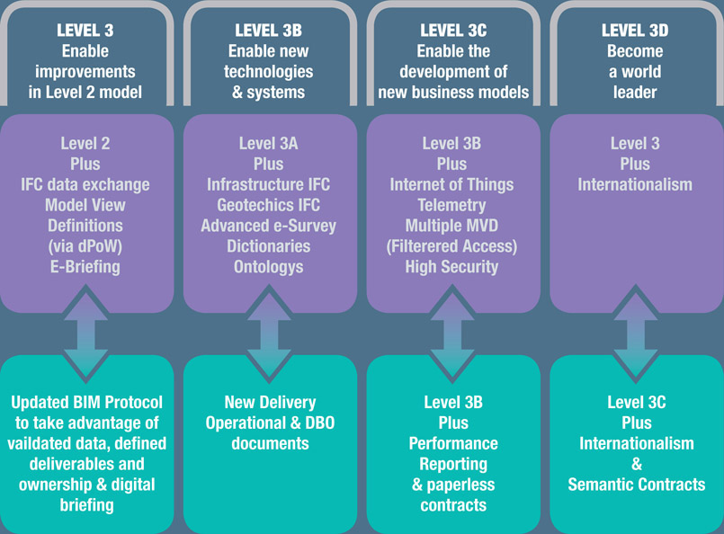
Figure 4.5
The four stages of the Digital Built Britain strategy
Although the government mandate is for BIM Level 2 on all centrally procured government projects by 2016, it should be remembered that the purpose of moving to the next maturity level of BIM adoption is to improve the efficiency and effectiveness of the design, construction and handover process.
There remains a danger that firms can become excessively reductive in just seeking to demonstrate Level 2 compliance, while neglecting to see it as a step along a path towards implementing the fullest possible collaborative effort on projects via BIM. That path should not only realistically recognise where each organisation is today, but also indicate a desire to eventually achieve the full collaborative benefits of a BIM Level 2 Strategy.
The Strategic Benefits and Goals of BIM Level 2
As a recap, it’s useful to reiterate the key benefits (as highlighted in the Government BIM Strategy) that accrue from successfully adopting BIM technology and processes:
- The implications of alternative design proposals can be evaluated with comparative ease.
- Projects are modelled in three dimensions (eliminating coordination errors and subsequent expensive change).
- Design data can be fed direct to machine tools, creating a link between design and manufacture, and eliminating unnecessary intermediaries.
- There is a proper basis for asset management subsequent to construction.
The high-level goals for any firm that implements BIM should be aligned with this, i.e.
- Improving the ease with which alternative design proposals are evaluated
- Reduction/elimination of coordination errors
- Reduction/elimination of unnecessary intermediate steps between design and construction procurement/manufacture
- Providing a reliable information base for post-construction asset management.
Senior Sponsorship and Firm-Wide Commitment
As you consider this list, it’s worth imagining what the future might look like for your firm.
- What would these look like as a set of SMART objectives tailored to each staff level?
- What sort of preparation and reporting regime would need to be in place for staff to quantify improvements through BIM?
As you wrestle with these questions, you will realise that the achievement of these goals requires senior sponsorship, large-scale resource commitment and a regime of regular progress reporting. In essence, these goals need to become a stated and supported part of the organisation’s overall business strategy.
Quantifying Success
At this point, you should ask yourself how these outcomes are currently measured.
For instance:
- In respect of comparing proposals, what sort of criteria do you think are the most challenging to communicate and difficult for clients to evaluate? How might BIM improve the quality of visual communication about sustainability strategies, engineering analysis results, proof of fit and coordination for access and maintenance, and cost and programme implications of a design change?
- Client feedback: Your marketing team should conduct a survey of what representatives of major clients found easy and difficult to evaluate from your most recent proposals for a design change or alternative construction approach.
- Hold a BIM open day in which you invite client representatives to view a range of additional deliverables derived from the model. Ask for feedback on how the resulting data would affect the ease of evaluating the pros and cons of alternative proposals.
- Beyond just 3D visualisations, what other kinds of BIM outputs have clients considered in order to facilitate their evaluation of proposals? Graphs? Schedules? Colour-coded plans?
- Will the cost of implementing these new workflows be recouped on the project, or does the benefit come primarily from improved client relations and the development of a marketable service differentiator?
- How does your team currently track coordination issues through to resolution? If the course of each discussion is buried in a set of email exchanges, the evidence of reduced error will remain largely anecdotal. For tracking issues to resolution, you should follow customer service best practices by establishing a consistent format for recording the progression of any issues, as well as a protocol for filing and retrieving different types of project-related communications. (In the absence of a dedicated project data management system, emails and project team meeting minutes can still provide a source of data to compare how quickly discussions about coordination are being resolved.)
- As a shared project resource, how could the federated model and associated design data have significantly reduced the likelihood of coordination issues either arising or being perpetuated?
- Contact fabricators and investigate the benefit of using the model for off-site manufacture of specific components in order to accelerate aspects of the construction process.
If these steps have been implemented properly and with the leadership of a BIM champion who can galvanise staff-wide commitment, they will provide quantitative evidence of business improvement.
Remember that it remains the firm’s prerogative to phase the introduction of these outputs into the design/construction process in a cost-effective manner. It is not acceptable to simply ignore client feedback, or postpone indefinitely any actions that should follow from it.
That said, implementing this goal may require a shift in office culture towards shared project responsibility and performance transparency. If a blame culture holds sway, no-one will want to be open about the amount design re-work and coordination errors that currently occur on projects.
Conclusion
We have reviewed the BIM Maturity Levels in terms of how drawings and other project-related data are organised and exchanged between team members. At its most basic, BIM Level 2 is implemented in organisations that develop the project in 3D and use BIM collaboration software as a ‘bridge’ to combine their exported model renditions into a federated model in readiness for coordination sessions.
The ability to walk through, examine and mark up views within the federated model should not be restricted to enthusiastic technicians. For BIM Level 2, all technical coordinators should be able to use prepared 3D models this way.
BIM Level 2 has a strategic significance for organisations that understand the potential for the kind of data that is embedded in and linked to each model to enhance communication with other business processes. Data from the model can be linked to databases for material procurement, project management schedules, and staff resourcing schedules. It is important for your organisation to identify specific objectives in order to leverage this data for its own benefit and for that of the project.