
05
The Challenges and Benefits of BIM Coordination: 3D, 4D and 5D

Introduction
The goal of coordination is to achieve comprehensive and pre-emptive coherence of design and construction. This is as important within each specialty as it is across all disciplines, drawing types and scales. Incoherent design is not only costly and time-consuming to rectify on site. It is also unsafe.
There are two means by which BIM can facilitate this effort:
- Computer automation
- Computer assistance.
This chapter explores these methods as well as the key challenges involved and actual processes employed in using BIM to achieve design coherence spatially (3D), sequentially (4D) and quantitatively (5D).
The key coverage of this chapter is as follows;
- Coordination challenges
- The practical steps involved in coordination through BIM.
Coordination Challenges
Coordination involves a regime of preventive scrutiny. It seeks to eliminate incoherent communication in design and construction. Comprehensive coordination may be subdivided into five distinct challenges:
- Drawing set coordination and scale-appropriate drawing contents
- Coordination with survey position of the existing and proposed building, its zones and phases
- Safety, accessibility, operations and maintenance (O & M) provisions
- Adequacy of the spatial provision, construction sequence and quantities required for the intended design and construction of elements belonging to each discipline
- Adequacy of the complementary provision, including clearances, for the intended construction interfaces between disciplines.
There are six key aspects to the elimination of coordination errors:
- For each deliverable type, prior agreement on consistent documented standards, templates and approved exemplars
- For all disciplines, prior agreement on sheet sizes and scales, projected sheet lists and consistently named and located zones that will ensure adequate drawing coverage for the project at the required scale
- Pre-defined project-specific element libraries to accommodate the full range of deliverables and drawing scales
- Appropriate balance between detail automatically derived from 3D elements and that which is routinely applied through 2D drafting and annotations
- Adequate internal cycles of scrutiny to ensure coherence across all aspects of design intent
- Cycles of project team scrutiny to ensure that all disciplines have made adequate complementary provisions for each other as well as clearances for safety, accessibility, operations and maintenance.
There are 10 key ways in which BIM facilitates coherent output in a way that is much more difficult to implement through multiple separate CAD files. They can be divided into two categories: those automated by the computer and those assisted by the computer. The latter require additional visual scrutiny. Figure 5.1
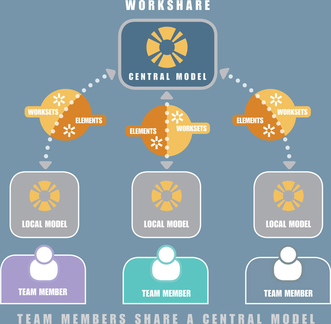
Concurrent updates to the Central Model in BIM Figure 5.2
Views and elements from structural model re-used in architectural GAs2 Figure 5.3
1:50 view (right) is derived from 1:100 section (left)2 Figure 5.4
Project-wide grid lines are consistent for all floor levels2 Figure 5.5
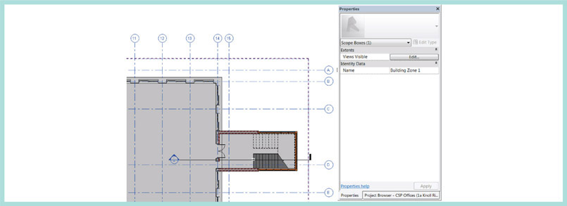
Revit scope box used to control grid line offsets2 Computer-assisted coordination Figure 5.6
View template applies consistent properties to multiple drawing views2 Figure 5.7
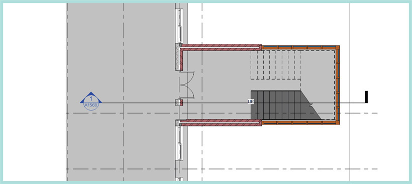
Section label automatically references the associated sheet2 Figure 5.8
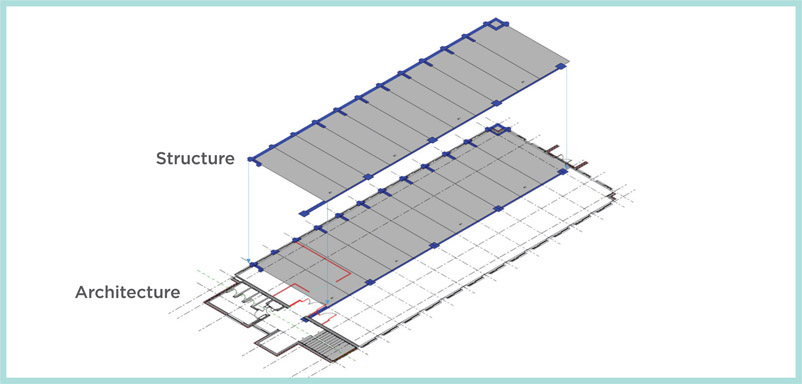
Structural model (green) must be coordinated with architecture2 Figure 5.9
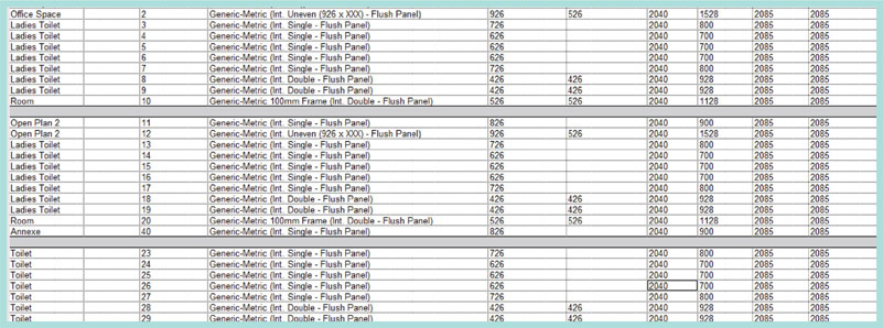
Door schedule that automatically updates with changes to the model2 Again, despite these benefits, there remains a need to scrutinise the schedules to identify extraneous and uncoordinated items. Implementing BIM poorly can lead to difficulties in coordination. Some examples of common mistakes are listed below. Figure 5.10
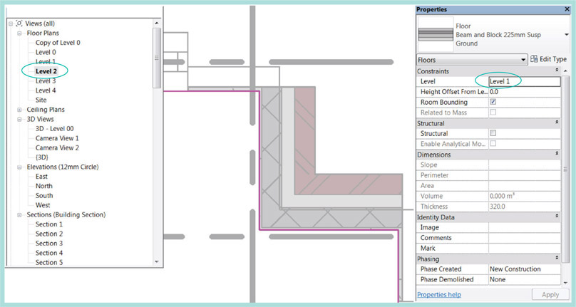
Plan of floor slab mistakenly inserted on level 1 in level 2 view2Why use BIM?
Computer automated coordination


What can Go wrong?
The Practical Steps Involved in Coordination through BIM
So, assuming that the above issues have been resolved, let us consider the practical processes involved in eliminating coordination errors through BIM.
Coordination Roles
The PAS-1192-2 documentation provides guidance and illustrations to explain how spatial coordination should be conducted in BIM. Key to this is the role of the task team, which PAS-1192-2 describes in this way:
‘Task Teams are any team assembled to complete a TASK.’
‘Examples: Architectural Task Team; Structural Task Team or multi-disciplinary Task Team to design a specialist part of the project, say a bespoke curtain wall. This may also include the specialist and professional design teams collaborating to complete that task.’
It goes on to state that meetings for spatial coordination utilising BIM will bring together three distinct roles (Chapter 6, Table 6.1):
- Technical coordinators (for each discipline and specialty): In PAS-1192, these are termed task team interface managers.
- Lead Designer’s Project Architect/Engineer: These may be called upon to arbitrate otherwise unresolved design issues.
- BIM Coordinators: Responsible for preparing the models for spatial coordination meetings.
While project architects, engineers and technical co-ordinators are familiar participants in coordination meetings, the use of the model will be facilitated by the BIM Coordinator. Typically, the BIM Coordinator would be a senior technician on the project, well versed in the key coordination issues and capable of setting up and navigating through the model.
Preparation for the Model Coordination Process
There are a number of key steps involved in preparing for the organised exchange of models for coordination:
- Sub-divide the overall project into several models distinguished by volume and discipline, or specialty. Tabulate development responsibility for each model over the course of the project (see Chapter 2, Table 2.4). The decision about what type of file to share is based on the permitted purpose agreed in the BIM protocol. For spatial coordination, all that is required is to provide each model in a format that can be opened by the application defined in the Post-Contract BIM Execution Plan for accomplishing that purpose (see Chapter 2, Table 2.1).
- Establish a Common Data Environment, i.e. a secure, managed and mutually accessible project repository capable of storing and sharing all models and issuing update notifications about them to project participants.
- Establish a file naming protocol to easily distinguish each model contribution, including its revision status. (see ‘Using a data storage naming protocol’ in Chapter 3). Define status codes that communicate its suitability for a given purpose, such as review or coordination see Chapter 8, section entitled Assigning and notifying of model status.
- At agreed regular intervals, and on request, each discipline’s project lead (known as the task team leader) should approve one or more work-in-progress models for sharing with others, but only after reviewing and approving the derived output.
- These models are then uploaded to the Common Data Environment in compliance with the agreed timing, standards and naming convention specified in the Post-Contract BIM Project Execution Plan. An update notification should be automatically issued to other project participants.
Clash Avoidance, Detection and Resolution
Preventing clashes is a far better strategy than fixing those that could have been avoided in the first place. The project team’s approach to coordination should prioritise clash avoidance.
- Typically, clashes can be avoided by pre-assigning the locations and routes of each discipline’s work to particular building zones and levels. Major runs of primary ductwork should be assigned to specific riser locations, while secondary distribution should be assigned to specific levels in the ceiling. On this basis, clashes should only occur at points of exit from and access to service risers. For BIM Level 2, a proprietary application – such as Bentley Navigator®, Autodesk Navisworks®, Tekla BIMsight® and Solibri Model Checker® – should be used to provide a unified view of the combined multi-disciplinary (i.e. federated) model. A key feature of such applications is the ability to identify interferences between components – i.e. clash detection. In testing for these, selection criteria are applied to reveal specific types of clashes, such as occur between structure, partitions and pipework, or between ceilings and ductwork.
-
Spatial coordination meetings should be scheduled and chaired by the technical coordinator for the Lead Designer. In PAS-1192-2, technical coordinators are described as ‘task team interface managers’. On behalf of their respective teams, their role is to meet regularly and ensure that all disciplines have made adequate complementary provisions for each other and clearances for safety, accessibility, operations and maintenance.
For spatial coordination, technical coordinators should visually inspect both combined multi-disciplinary models and the drawings that have been derived from them. Assistance in touring the 3D environment should be provided by role of BIM coordinator. As outlined earlier, this is not necessarily a dedicated BIM Manager, but instead a technician on the project who has demonstrated a high aptitude, after initial training, for producing design deliverables and for touring and setting up views in the 3D model.
When conflicts or the lack of complementary provisions are detected, the technical coordinators’ role is to decide and record the design changes that will be required to resolve these clashes. If they reach an impasse, the lead designer’s project architect or engineer is responsible for arbitrating these design decisions.
- Once the design changes that are needed to resolve a clash have been agreed and approved, the technical coordinators should implement them through their respective design teams. The work-in-progress models will be updated and the resulting revisions shared with notifications of changes through the Common Data Environment.
- After downloading the revised models and in conjunction with the BIM coordinator, each technical coordinator should conduct a final check to ensure that the agreed design changes are reflected in each model.
Construction Coordination in BIM: 4D
The coordination of construction processes can be improved by using BIM software to link elements in the model to tasks created in a project management application. This creates a time-lapse animation of the building sequence in which elements will become visible in the same relative order as their respective tasks are organised in the construction sequence. The time dimension is added to the 3D model and explains why this is called 4D.
Benefits of 4D
In one sense, contractors ‘design’ the construction sequences needed to build the completed facility. A key benefit of 4D simulation is that its resemblance to the physical reality makes it easy for all stakeholders and the whole project team to evaluate alternative construction processes in terms of relative speed, effectiveness and safety.
Typically, on large and centrally procured projects this will involve integrating the detailed logistics from the project schedule of a complex multi-tier supply chain with the 3D model. Nevertheless, the use of 4D is equally valuable to SMEs for reviewing different options for smaller refurbishment projects, by visualising alternatives for the phasing of the decant and handing back of completed parts of the building.
‘Forward-thinking design and construction teams also use 4D to match an indicative assembly sequence to their models and thereby explain the order of element assembly needed to complete the project.
For instance, on the King Abdullah University of Science and Technology (KAUST) project, the Revit® design model was re-developed by Oger International and Gehry Technologies in CATIA® as a detailed virtual constructional model.
4D animations were then developed that showed project managers and site operatives exactly how the complex construction sequence for the solar tower could be implemented effectively and safely.’ (see figs 5.11 and 5.12)
What Data is Required for 4D?
The development of a 4D simulation requires the integration of two key software resources:
- 3D model of the project, divided into constructional detail.
- Project management application file containing a schedule of tasks, abridged to correlate to the level of detail in the associated model.
Early on in the project lifecycle, the model will only contain elements that convey the architectural and engineering intentions of the design suppliers. This design intent model might be useful for creating an indicative animation sequence, but it will not contain elements representative of each task in the construction programme.
In contrast, the virtual construction model replaces the design intent model being developed in further detail by the main contractor working in conjunction with its supply chain. Elements, previously modelled monolithically, must be sub-divided by storey height and movement joints, and into assembly and pre-cast components. Element sub-division would be implemented either through a function of the native application, or in the BIM coordination application itself.

Figure 5.11 and 5.12
a view of the model showing the construction sequence on KAUST and an actual photo of the construction site3
There will also be a requirement to model additional site elements, including:
- Existing buildings and other site topography (if not modelled already)
- Temporary buildings and erected site machinery
- Scaffolding and falsework.
As PAS-1192-2 explains, ‘the Project Information Model is developed firstly as a design intent model, showing the architectural and engineering intentions of the design.’suppliers. Then the PIM is developed into a virtual construction model containing all the objects to be manufactured, installed or constructed.’
Challenges of matching model elements to project management software task data
Creating the 4D animation involves matching imported project scheduling tasks to model elements. In terms of available data, it might seem easy enough for the BIM Manager to obtain the latest project schedule in a compatible format from the Project Manager, and import this into the 4D software along with a rendition of the 3D model appropriate to the required simulation detail. Nevertheless, these inputs are not necessarily useable without significant amendment.
For instance, the complete schedule would typically cover the entire project duration and contain far more detail about indirect site activities and milestones than those relating directly to the construction process and to the current level of model detail.
Also, it is a challenge to produce a 4D animation for simulating a sequence of coatings or surface treatments. Typically, these are part of the specification, but they are not modelled in 3D. In the use of Autodesk Navisworks, this is addressed by extending the range of appearance definitions such that, during the animation, each treatment is represented by a distinct colour change.
Tips for implementing 4D successfully within your firm
Below are a number of initiatives that would facilitate the adoption of 4D.
-
Develop a preparatory 4D awareness campaign using data from a smaller existing project. This would take time to produce, but once complete, it would allow end-users to see the benefits of 4D in simulated project meeting workshops. At the end of each workshop, attendees can be surveyed to gain feedback on the value of the technology.
In this exercise, it would be useful to identify some familiar project scenarios and develop alternative construction sequences for them in 4D. Accomplishing this involves the BIM sponsor and BIM champion (Chapter 3, section entitled Leadership roles in firms that are new to BIM) joining forces to gain the commitment of time and effort from other staff to provide realistic scenarios and help in developing useful 4D alternatives to address them. The authors of a study entitled BIM and D Planning: a holistic study of the barriers and drivers to widespread adoption1 highlighted the fact that the adoption of 4D in construction planning was directly attributable to bridging the gap between the technology, end-users and their existing processes. In contrast, many BIM managers spend too much time teaching staff how to create and update the model and not enough time familiarising the design team on how the model would be used in a realistic project context.
- Refine the use of 4D on projects modelled in BIM into a number of specific advantageous and quantifiable objectives:
- a In the BIM Project Execution Plan, mandate the use of a global Task ID parameter on all elements in all models. Use component schedules to check on this regularly.
- b After reviewing the project schedule, use named selection sets to group elements by the related task and assign to them the correct Task ID value.
- c At the beginning of the construction phase, add elements to a model representing site features, facilities and topography prior to excavation. Combine this with the 3D design intent model to produce the virtual construction model. Develop a 4D simulation of the high-level baseline project plan to complement presentations explaining the overall construction sequence.
- d Categorise sub-element visibility each model element into coarse, medium and fine display (see Chapter 9 on Level of Definition). This allows the model to revert and be export to a lower of detail that matches the task detail required for producing 4D.
- e For the first few months of project meetings in the construction phase, collaborate with the construction manager on monthly post-meeting 4D visualisations showing major changes to this baseline schedule as a visual comparison with actual construction progress.
- f In later months and prior to team meetings, confer with the construction manager to produce 4D simulations of major alternatives for the project schedule, especially those showing how time could be recouped.
- g Work with the mechanical contractor’s detailed programme to produce a sample 4D animation of a plant room construction sequence.
- h Establish a programme of progressively more detailed modelling efforts over the next two years, dividing ever more of the model’s major monolithic elements into construction parts for use in 4D. These would include slab bays, sections of jump-formed structures and unitised partition system lengths.
Quantification in BIM: 5D
Quantification in BIM can range from automated comparison of the schedule of accommodation against design areas (i.e. programme validation) to room-by-room FF&E schedules to the extraction of material quantities.
It is important to distinguish elemental cost planning (which, during design development, divides the project cost into the distinct functions provided by the scheme) from estimating (which contractors use to quantify the materials, labour and equipment needed to complete a construction project).
Cost schedules are automatically derived from BIM by linking unit costs to corresponding components of the model. This capability yields better result in counting items, than applying the standard methods of measurement to them. Yet, both require a regime of regularly purging the model of extraneous elements. Otherwise, the schedule will count additional items that have been inadvertently inserted into the model and that are superfluous to the design intent.
Scheduling quantities from BIM also does not obviate reliance upon professional surveying expertise to carry out building cost planning. This work includes measurement of the facilitating and contractor designed works, inclusion of the provisional sums, preliminaries, contingencies and non-measurable items that must also be considered.
Challenges of 5D BIM
There are six main challenges involved in deriving ‘real world’ benefits from 5D BIM:
- The grouping and breakdown of model components into their respective cost analysis elements depends on the level of definition (see Chapter 9). The process of extracting quantities can be hampered by a lack of sufficient detail. Also, the design team is not focused on developing the model in a way that ensures that its constituents will always be assigned to the correct cost categories.
- In the Standard Form of Cost Analysis, there are inclusions and exclusions for each element definition. For instance, as a part of substructure, the lowest floor construction (section 1.1.3) does not include basement walls. The latter should be categorised with external walls (section 2.5). Equally, raised access flooring is grouped with Floor finishes (section 3.2), instead of Floors (section 2.2.1).
- Dimensional parameters of model elements do not automatically yield the required measurement data. For example, for cost analysis, the elemental quantity for slabs is gross internal floor area (to the inner face of the external wall); by contrast, the larger area derived from the model is measured to the slab perimeter. Again, downstand and upstand floor beams are not grouped with the Frame (section 2.1), but with the Upper Floors (section 2.2).
- There is a need to provide specification and design criteria to indicate the required performance of each element. This data will inform the unit cost calculation.
- It may be difficult to divide the finishes of continuous walls and floors extending beyond individual rooms. Some finishes might not even be modelled, but instead be added into the specification.
- Construction classification systems need to be rationalised to allow models to interoperate between them. Uniclass 2 is currently the definitive system for the construction specification in the UK, whereas the New Rules of Measurement 2, used for cost classification, is structured differently.
In order to address these challenges, the BIM Manager must make a strategic reckoning to identify where exactly the effort required to break down and re-group 3D model elements represents a significant improvement on traditional methods of measurement that use 2D drawings. This would be where BIM processes impart either greater speed or accuracy than would be achievable by the latter.
In many cases, it is preferable to employ a hybrid approach that integrates the benefits of 5D BIM with traditional costing techniques. 5D is best used for approximations that help decision-makers compare the cost impact of various design and construction alternatives and to quantify FF&E accurately.
Conclusion
In terms of reducing the significant costs incurred by rework and to improve the understanding and safety of proposed methods, coordination should be at the heart of BIM Level 2 implementation.
The BIM Project Execution Plan should clearly define the benefits, scope, normative processes and outputs of 3D, 4D and 5D BIM.
Within each firm, the BIM Sponsor and BIM Champion must develop and implement a gradual programme of BIM awareness sessions to familiarise staff with these model outputs by simulating the experience (beyond static visualisations and drawings) of using them. They should also spearhead the gradual incorporation of the technology into project coordination meetings and planning processes.
The next chapter considers how this transition is effected through organisational change.