
CHAPTER 7
BACKBONE NETWORKS
THIS CHAPTER examines backbone networks (BNs) that are used to link LANs together and to link BNs to WANs. We begin with the various types of devices used in BNs and discuss several backbone architectures. The chapter ends with a discussion of how to improve BN performance and of the future of BNs.
OBJECTIVES ![]()
- Understand the internetworking devices used in BNs
- Understand several common backbone architectures
- Be familiar with gigabit Ethernet
- Understand the best practice recommendations for backbone design
- Be aware of ways to improve BN performance
CHAPTER OUTLINE ![]()
7.2 BACKBONE NETWORK COMPONENTS
7.3 BACKBONE NETWORK ARCHITECTURES
7.3.1 Backbone Architecture Layers
7.4 THE BEST PRACTICE BACKBONE DESIGN
7.5 IMPROVING BACKBONE PERFORMANCE
7.5.1 Improving Computer and Device Performance
7.5.2 Improving Circuit Capacity
7.6 IMPLICATIONS FOR MANAGEMENT
7.1 INTRODUCTION
Most business organizations realize that information must be stored, retrieved, analyzed, acted on, and shared with others at a moment's notice. Without an enterprisewide network or an Internet connection, moving information from one department LAN to another or to customers is difficult.
Interconnecting the organization's diverse networks is critical. A backbone network (BN) is a high-speed network that connects many networks. BNs typically use higher-speed circuits to interconnect a series of LANs and provide connections to other BNs, MANs, WANs, and the Internet. A backbone that connects many BNs spanning several nearby buildings for a single organization is often called a campus network. A BN also may be called an enterprise network if it connects all networks within a company, regardless of whether it crosses state, national, or international boundaries.
We begin this chapter by describing several commonly used devices in the BN and then showing how those can be used to create different backbone architectures with different performance capabilities. Backbones used to be built with special technologies, but today most BNs use high-speed Ethernet.
7.2 BACKBONE NETWORK COMPONENTS
There are two basic components to a BN: the network cable and the hardware devices that connect other networks to the BN. The cable is essentially the same as that used in LANs, except that it is often fiber optic to provide higher data rates. The hardware devices can be computers or special-purpose devices that just transfer messages from one network to another. These include switches, routers, and gateways (Figure 7.1).
7.2.1 Switches
Most switches operate at the data link layer. They connect two or more network segments that use the same data link and network protocol. They understand only data link layer protocols and addresses. They may connect the same or different types of cable. These are the same layer-2 switches discussed in Chapter 6 in that they use the data link layer address to forward packets between network segments (Figure 7.2). They learn addresses by reading the source and destination addresses.
7.2.2 Routers
Routers operate at the network layer. They connect two or more network segments that use the same or different data link protocols but the same network protocol. They may connect the same or different types of cable. Routers are the “TCP/IP gateways” that we first introduced in Chapter 5. Routers strip off the data link layer packet, process the network layer packet, and forward only those messages that need to go to other networks on the basis of their network layer address (Figure 7.3).
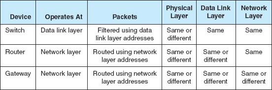
FIGURE 7.1 Backbone network devices
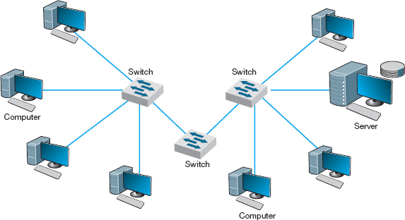
FIGURE 7.2 Use of switches to connect local area network segments
Routers may be special purpose devices or special network modules in other devices (e.g., wireless access points for home use often include a built-in router). In general, they perform more processing on each message than switches and therefore operate more slowly.
One major feature of a router is that it can choose the “best” route between networks when there are several possible routes between them. Because a router knows its own location, as well as the packet's final destination, it looks in a routing table to identify the best route or path.
One other important difference between a router and a switch is that a router processes only those messages that are specifically addressed to it. Switches process all messages that appear on the network and forward them to the appropriate network on the basis of their data link layer address. Switches simply forward the message unchanged to the other network. In contrast, because routers operate at the network layer, the router's data link layer must first recognize that the incoming message is specifically addressed to the router at the data link layer level before the message is passed to the network layer for processing. The router will then process the message by building an entirely new data link layer packet, then transmit it to the other network.
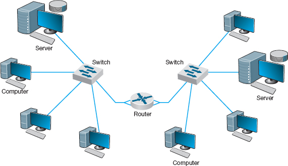
FIGURE 7.3 Use of routers to connect local area networks
The router attempts to make no changes to the network layer packet and user data it receives. (As noted previously, it creates a new data link layer packet.) Sometimes, however, changes are needed, such as when the maximum data link layer packet size on one network is different from another, which forces the router to split a message into several smaller messages for transmission.
7.2.3 Gateways
Gateways operate at the network layer and use network layer addresses in processing messages. Gateways are more complex than switches or routers because they are the interface between two or more dissimilar networks. Gateways connect two or more networks that use the same or different (usually different) data link and network protocols. They may connect the same or different types of cable. Some gateways operate at the application layer as well. Gateways process only those messages explicitly addressed to them (i.e., using their data link layer address) and route those messages that need to go to other networks (Figure 7.4).
Gateways translate one network layer protocol into another, translate data link layer protocols, and open sessions between application programs, thus overcoming both hardware and software incompatibilities. A gateway may be a stand-alone computer with several NICs and special software or a front-end processor connected to a mainframe computer.
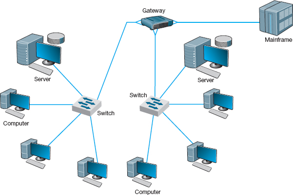
FIGURE 7.4 Use of gateways to connect local area networks and a mainframe
Gateways used to be common, but as TCP/IP has become the dominant network protocol, they are quickly fading from use.
7.2.4 A Caution
One warning is in order. The terminology used in the marketplace may differ substantially from that in the preceding discussion. Many new types of switches, routers, and gateways are being developed, so that one vendor's “switch” may actually provide the functions of a “router.” Layer-3 switches function in the same way as layer-2 switches discussed previously, but they switch messages on the basis of their network layer address (usually IP address). These switches provide the best of both switches and routers. They can be used in place of routers but provide the benefits of traditional layer-2 switches: much faster transmission and more simultaneously active ports than routers.
7.3 BACKBONE NETWORK ARCHITECTURES
The backbone architecture refers to the way in which the backbone interconnects the networks attached to it and how it manages the way in which packets from one network move through the backbone to other networks.
While there are an infinite number of ways in which network designers can build backbone networks, there are really only three fundamental architectures that can be combined in different ways. These architectures are routed backbones (routers that move packets on the basis of network layer addresses), switched backbones (switches that move packets based on data link layer addresses), and virtual LANs (switches that move packets through LANs that are built virtually, not using physical location).
These architectures are mixed and matched to build sets of BNs. Before we discuss these architectures, we first must discuss the way in which network designers think about backbone designs and how to combine them; that is, the different layers of backbones that exist in most organizations today.
7.3.1 Backbone Architecture Layers
Network designers often think about three distinct technology layers1 when they design BNs. The layer closest to the users is the access layer, the technology used in the LANs attached to the BN as described in the previous chapter (e.g., 100Base-T, wireless Ethernet) (Figure 7.5). Although the access layer is not part of the BN, the technologies used in the LANs (or access layer) can have major impacts on the design of the backbone.
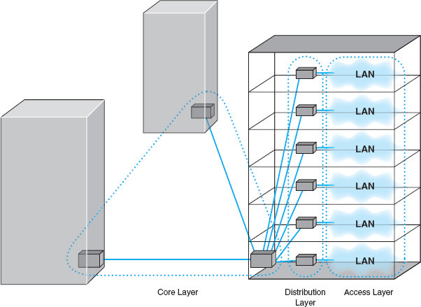
FIGURE 7.5 Backbone network design layers. LAN = local area network
The distribution layer is the part of the backbone that connects the LANs together. This is the part of the backbone that contains the “TCP/IP gateways” described in Chapter 5. It usually runs throughout one building.
The core layer is the part of the backbone that connects the different BNs together, often from building to building. The core layer is technologies used in the campus network or the enterprise network. Some small organizations are not large enough to have a core layer; their backbone spans only the distribution layer. Other organizations are large enough that they have a core network at several locations that are in turn connected by WANs.
In the sections that follow, we describe the three basic BN architectures and discuss at which layer they are often used. We focus on TCP/IP networks when comparing these architectures. We assume that you are comfortable with the material on TCP/IP in Chapter 5; if you are not, you may want to go back and review the last section of the chapter, entitled TCP/IP Example, before you continue reading.
7.3.2 Switched Backbones
Switched backbones are probably the most common type of BN used in the distribution layer (i.e., within a building); most new building BNs designed today use switched backbones. They also are making their way into the core layer as the campus backbone, but routed backbones still remain common.
Switched backbone networks use a star topology with one switch at its center. Figure 7.6 shows a switched backbone connecting a series of LANs. There is a switch serving each LAN (access layer) which is connected to the backbone switch at the bottom of the figure (distribution layer). This figure implies that the LAN switches are close to the computers in their LANs and farther from the backbone switch. Most organizations now use switched backbones in which all network devices for one part of the building are physically located in the same room, often in a rack of equipment. This form of switched backbone is shown graphically in Figure 7.7. This has the advantage of placing all network equipment in one place for easy maintenance and upgrade, but it does require more cable. In most cases, the cost of the cable itself is only a small part of the overall cost to install the network, so the cost is greatly outweighed by the simplicity of maintenance and the flexibility it provides for future upgrades.
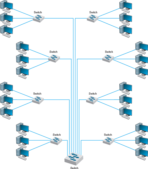
FIGURE 7.6 Switched backbone network design
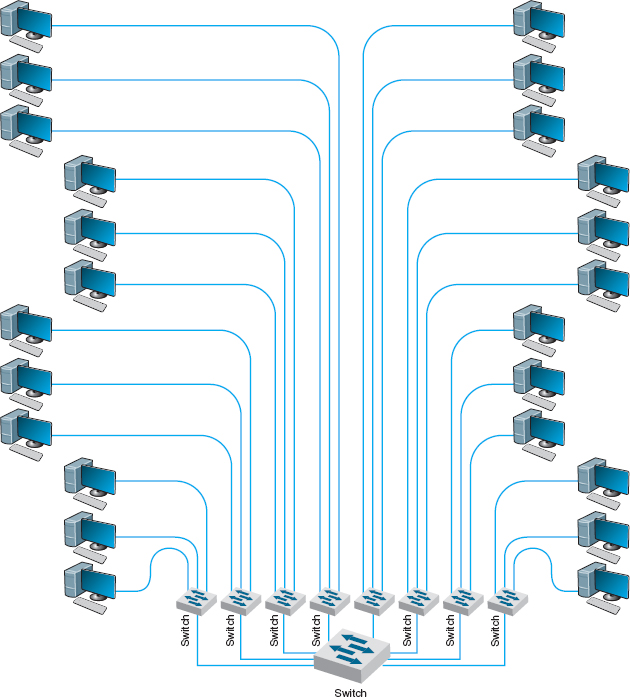
FIGURE 7.7 Rack-mounted switched backbone network design
The room containing the rack of equipment is sometimes called the main distribution facility (MDF) or central distribution facility (CDF). Figure 7.8 shows a photo of an MDF room at Indiana University. Figure 7.9 shows the equipment diagram of this same room. The cables from all computers and devices in the area served by the MDF (often hundreds of cables) are run into the MDF room. Once in the room, they are connected into the various devices. The devices in the rack are connected among themselves using very short cables called patch cables.
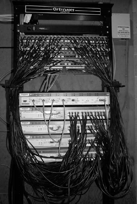
FIGURE 7.8 An MDF with rack-mounted equipment. A layer-2 chassis switch with six 100Base-T modules (center of photo) connects to four 24-port 100Base-T switches. The chassis switch is connected to the campus backbone using 1000Base-F over fiber-optic cable. The cables from each room are wired into the rear of the patch panel (shown at the top of the photo), with the ports on the front of the patch panel labeled to show which room is which. Patch cables connect the patch panel ports to the ports on the switches
With rack-mounted equipment, it becomes simple to move computers from one LAN to another. In the switched backbone design as shown in Figure 7.6, for example, all the computers in the same general physical location are connected to the same switch and thus share the capacity of the switch. Although this often works well, it can cause problems if many of the computers on the switch are high-traffic computers. For example, in Figure 7.6, if all the busy computers on the network are located in the upper left area of the figure, the switch in this area may become a bottleneck.
7.1 SWITCHED BACKBONES AT INDIANA UNIVERSITY
MANAGEMENT FOCUS
At Indiana University we commonly use switched backbones in our buildings. Figure 7.10 shows a typical design. Each floor in the building has a set of switches and access points that serve the LANs on that floor. Each of these LANs and WLANs are connected into a switch for that floor, thus forming a switched backbone on each floor. Typically, we use switched 100Base-T within each floor.
The switch forming the switched backbone on each floor is then connected into another switch in the basement, which provides a switched backbone for the entire building. The building backbone is usually a higher speed network running over fiber-optic cable (e.g., 100Base-F or 1 GbE). This switch, in turn, is connected into a high-speed router that leads to the campus backbone (a routed backbone design).
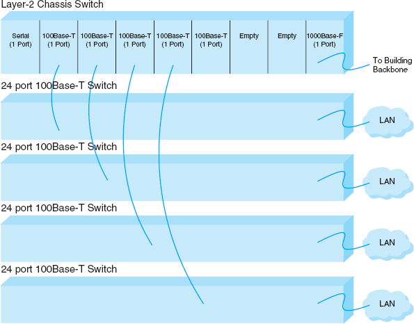
FIGURE 7.9 MDF network diagram
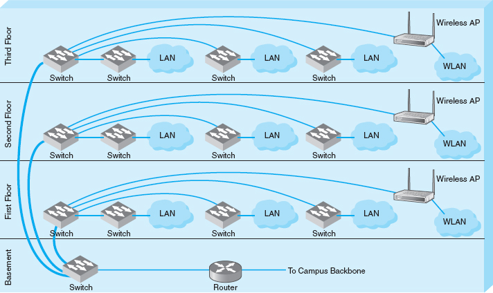
FIGURE 7.10 Switched backbones at Indiana University
With an MDF, all cables run into the MDF. If one switch becomes overloaded, it is straightforward to unplug the cables from several high-demand computers from the overloaded switch and plug them into one or more less-busy switches. This effectively spreads the traffic around the network more efficiently and means that network capacity is no longer tied to the physical location of the computers; computers in the same physical area can be connected into different network segments.
Sometimes a chassis switch is used instead of a rack. A chassis switch enables users to plug modules directly into the switch. Each module is a certain type of network device. One module might be a 16-port 100Base-T switch, another might be a router, whereas another might be a 4-port 1000Base-F switch, and so on. The switch is designed to hold a certain number of modules and has a certain internal capacity, so that all the modules can be active at one time. For example, a switch with four 1000Base-T switches (with 24 ports each), and one 1000Base-F port would have to have an internal switching capacity of at least 97 Gbps ([4 × 24 × 1 Gbps] + [1 × 1 Gbps]).
The key advantage of chassis switches is their flexibility. It becomes simple to add new modules with additional ports as the LAN grows and to upgrade the switch to use new technologies. For example, if you want to add gigabit Ethernet, you simply lay the cable and insert the appropriate module into the chassis switch.
7.3.3 Routed Backbones
Routed backbones move packets along the backbone on the basis of their network layer address (i.e., layer-3 address). Routed backbones are sometimes called subnetted backbones or hierarchical backbones and are most commonly used to connect different buildings within the same campus network (i.e., at the core layer).
Figure 7.11 illustrates a routed backbone used at the core layer. A routed backbone is the basic backbone architecture we used to illustrate how TCP/IP worked in Chapter 5. There are a series of LANs (access layer) connected to a switched backbone (distribution layer). Each backbone switch is connected to a router. Each router is connected to a core router (core layer). These routers break the network into separate subnets. The LANs in one building are a separate subnet. Message traffic stays within each subnet unless it specifically needs to leave the subnet to travel elsewhere on the network, in which case the network layer address (e.g., TCP/IP) is used to move the packet. For example, in a switched backbone, a broadcast message (such as an ARP) would be sent to every single computer in the network. A routed backbone ensures that broadcast messages stay in the one-network segment (i.e., subnet) where they belong, and are not sent to all computers. This leads to a more efficient network.
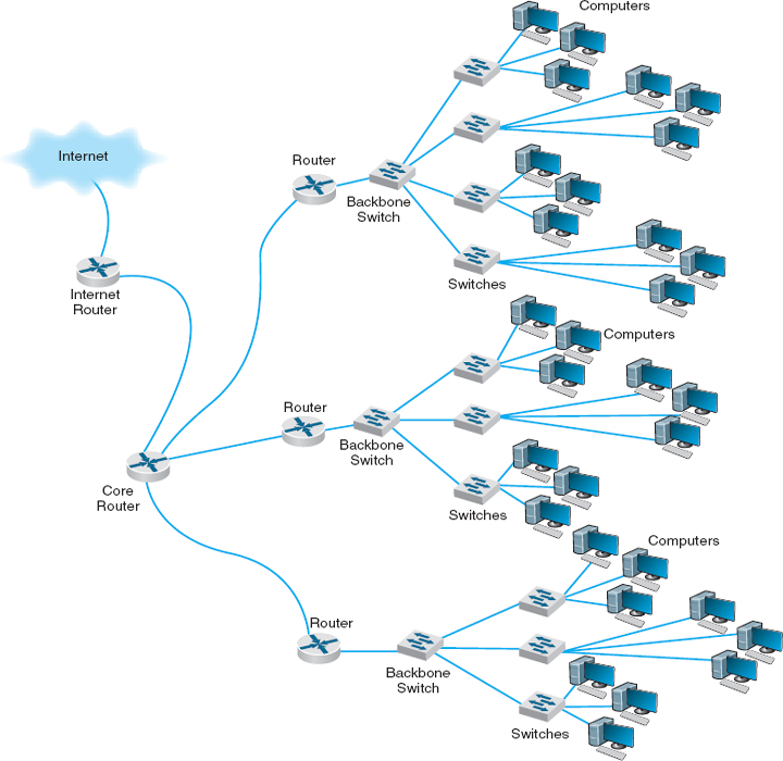
FIGURE 7.11 Routed backbone design
Each set of LANs is usually a separate entity, relatively isolated from the rest of the network. There is no requirement that all LANs share the same technologies. Each set of LANs can contain its own server designed to support the users on that LAN, but users can still easily access servers on other LANs over the backbone as needed.
The primary advantage of the routed backbone is that it clearly segments each part of the network connected to the backbone. Each segment (usually a set of LANs or switched backbone) has its own subnet addresses that can be managed by a different network manager. Broadcast messages stay within each subnet and do not move to other parts of the network.
A Day in the Life: Network Operations Manager
The job of the network operations manager is to ensure that the network operates effectively. The operations manager typically has several network administrators and network managers that report to him or her and is responsible for both day-to-day operations as well as long-term planning for the network. The challenge is to balance daily firefighting with longer-term planning; they're always looking for a better way to do things. Network operations managers also meet with users to ensure their needs are met. While network technicians deal primarily with networking technology, a network operations manager deals extensively with both technology and the users.
A typical day starts with administrative work that includes checks on all servers and backup processes to ensure that they are working properly and that there are no security issues. Then it's on to planning. One typical planning item includes planning for the acquisition of new desktop or laptop computers, including meeting with vendors to discuss pricing, testing new hardware and software, and validating new standard configurations for computers. Other planning is done around network upgrades, such as tracking historical data to monitor network usage, projecting future user needs, surveying user requirements, testing new hardware and software, and actually planning the implementation of new network resources.
One recent example of long-term planning was the migration from a Novell file server to Microsoft ADS file services. The first step was problem definition; what were the goals and the alternatives? The key driving force behind the decision to migrate was to make it simpler for the users (e.g., now the users do not need to have different accounts with different passwords) and to make it simpler for the network staff to provide technical support (e.g., now there is one less type of network software to support). The next step was to determine the migration strategy: a Big Bang (i.e., the entire network at once) or a phased implementation (several groups of users at a time). The migration required a technician to access each individual user's computer, so it was impossible to do a Big Bang. The next step was to design a migration procedure and schedule whereby groups of users could be moved at a time (e.g., department by department). A detailed set of procedures and a checklist for network technicians were developed and extensively tested. Then each department was migrated on a one-week schedule. One key issue was revising the procedures and checklist to account for unexpected occurrences during the migration to ensure that no data were lost. Another key issue was managing user relationships and dealing with user resistance.
With thanks to Mark Ross
There are two primary disadvantages to routed backbones. First, the routers in the network impose time delays. Routing takes more time than switching, so routed networks can sometimes be slower. Second, routers are more expensive and require more management than switches.
Figure 7.11 shows one core router. Many organizations actually use two core routers to provide better security, as we discuss in Chapter 10.
7.3.4 Virtual LANs
For many years, the design of LANs remained relatively constant. However, in recent years, the introduction of high-speed switches has begun to change the way we think about LANs. Switches offer the opportunity to design radically new types of LANs. Most large organizations today have traditional LANs, but many are considering the virtual LAN (VLAN), a new type of LAN-BN architecture made possible by intelligent, high-speed switches.
Virtual LANs are networks in which computers are assigned to LAN segments by software rather than by hardware. In the preceding section, we described how in rack-mounted collapsed BNs a computer could be moved from one hub to another by unplugging its cable and plugging it into a different hub. VLANs provide the same capability via software so that the network manager does not have to unplug and replug physical cables to move computers from one segment to another.
Often, VLANs are faster and provide greater opportunities to manage the flow of traffic on the LAN and BN than do the traditional LAN and routed BN architecture. However, VLANs are significantly more complex, so they usually are used only for large networks.
The simplest example is a single-switch VLAN, which means that the VLAN operates only inside one switch. The computers on the VLAN are connected into the one switch and assigned by software into different VLANs (Figure 7.12). The network manager uses special software to assign the dozens or even hundreds of computers attached to the switch to different VLAN segments. The VLAN segments function in the same way as physical LAN segments or subnets; the computers in the same VLAN act as though they are connected to the same physical switch or hub in a certain subnet. Because VLAN switches can create multiple subnets, they act like layer-3 switches or routers, except the subnets are inside the switch, not between switches. Therefore, broadcast messages sent by computers in one VLAN segment are sent only to the computers on the same VLAN.
Virtual LANs can be designed so that they act as though computers are connected via hubs (i.e., several computers share a given capacity and must take turns using it) or via switches (i.e., all computers in the VLAN can transmit simultaneously). Although switched circuits are preferred to the shared circuits of hubs, VLAN switches with the capacity to provide a complete set of switched circuits for hundreds of computers are more expensive than those that permit shared circuits.
We should also note that it is possible to have just one computer in a given VLAN. In this case, that computer has a dedicated connection and does not need to share the network capacity with any other computer. This is commonly done for servers.
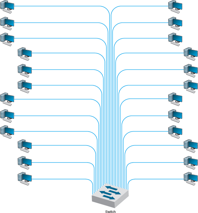
FIGURE 7.12 VLAN-based backbone network design
Benefits of VLANs Historically, we have assigned computers to subnets based on geographic location; all computers in one part of a building have placed in the same subnet. With VLANs, we can put computers in different geographic locations in the same subnet. For example, in Figure 7.12 a computer in the lower left could be put on the same subnet as one in the upper right—a separate subnet from all the other computers.
A more common implementation is a multiswitch VLAN, in which several switches are used to build the VLANs (Figure 7.13). VLANs are most commonly found in building backbone networks (i.e., access and distribution layers) but are starting to move into core backbones between buildings. In this case, we can now create subnets that span buildings. For example, we could put one of the computers in the upper left of Figure 7.13 in the same subnet as the computers in the lower right, which could be in a completely different building. This enables us to create subnets based on who you are, rather than on where you are; we have an accounting subnet and a marketing subnet, not a Building A and a Building B subnet. We now manage security and network capacity by who you are, not by where your computer is. Because we have several subnets, we need to have a router—but more on that shortly.
Virtual LANs offer two other major advantages compared to the other network architectures. The first lies in their ability to manage the flow of traffic on the LAN and backbone very precisely. VLANs make it much simpler to manage the broadcast traffic that has the potential to reduce performance and to allocate resources to different types of traffic more precisely. The bottom line is that VLANs often provide faster performance than the other backbone architectures.
The second advantage is the ability to prioritize traffic. The VLAN tag information included in the Ethernet packet defines the VLAN to which the packet belongs and also specifies a priority code based on the IEEE 802.1q standard (see Chapter 4). As you will recall from Chapter 5, the network and transport layers can use RSVP quality of service (QoS), which enables them to prioritize traffic using different classes of service. RSVP is most effective when combined with QoS capabilities at the data link layer. (Without QoS at the hardware layers, the devices that operate at the hardware layers [e.g., layer-2 switches] would ignore QoS information.) With the Ethernet packet's ability to carry VLAN information that includes priorities, we now have QoS capabilities in the data link layer. This means we can connect VOIP telephones directly into a VLAN switch and configure the switch to reserve sufficient network capacity so that they will always be able to send and receive voice messages.
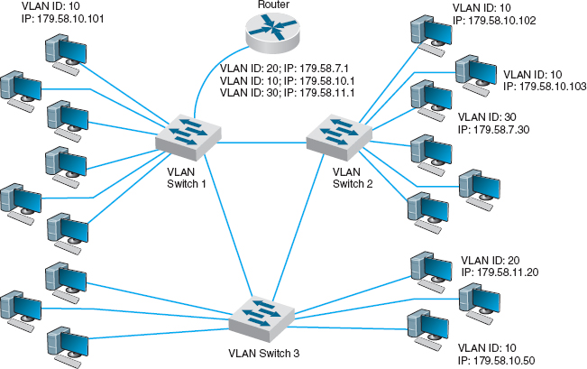
FIGURE 7.13 Multiswitch VLAN-based backbone network design
MANAGEMENT FOCUS
Shangri-La's Rasa Sayang Resort and Spa is a 5-star luxury resort hotel located on the scenic Batu Feringgi Beach in Penang, Malaysia. The resort has two main buildings, the 189-room Garden Wing and the 115-room Rasa Wing, with additional 11 private spa villas.
Over the years, the resort had installed three separate networks: one for the resort's operations, one for its POS (point-of-sales) system, and one for Internet access for guests (which was wired, not wireless). The networks were separate to ensure security, so that users of one network could not gain access to another.
As part of multimillion dollar renovation, the resort decided to upgrade its network to gigabit speeds and to offer wireless Internet access to its guests. Rather than build three separate networks again, it decided to build one network using VLANs. The resort installed 12 wireless access points and 24 VLAN switches, plus two larger core VLAN switches. The VLAN architecture provides seamless management of the wired and wireless components as one integrated network, and ensures robust performance and security.
___________
SOURCE: Source: “Wireless Access Amidst Lush Greenery of Penang Shangri-La's Resort,” HP ProCurve Customer Case Study, Hewlett-Packard, 2010.
The biggest drawbacks to VLANs are their cost and management complexity. VLAN switches also are much newer technologies that have only recently been standardized. Such “leading-edge” technologies sometimes introduce other problems that disappear only after the specific products have matured.
How VLANs Work VLANs work somewhat differently than the traditional Ethernet/IP approach described in the previous chapters. Each computer is assigned into a specific VLAN that has a VLAN ID number (which ranges from 1 to 1005 or to 4094 depending on whether the extended range standard is used). Each VLAN ID is matched to a traditional IP subnet, so each computer connected to a VLAN switch also receives a traditional IP address assigned by the VLAN switch (the switch acts as a DHCP server; see Chapter 5). Most VLAN switches can support only 255 separate VLANs simultaneously, which means each switch can support up to 255 separate IP subnets, which is far larger than most organizations want in any single device.
Computers are assigned into the VLAN (and the matching IP subnet) based on the physical port on the switch into which they are connected.2 Don't confuse the physical port on the switch (which is the jack the cable plugs into) with the TCP port number from Chapter 5; they are different—it's another example of networking using the same word (“port”) to mean two different things. The network manager uses software to assign the computers to specific VLANs using their physical port numbers so it is simple to move a computer from one VLAN to another.
When a computer transmits an Ethernet frame, it uses the traditional Ethernet and IP addresses we discussed in previous chapters (e.g., Chapters 4 and 5) to move the frame through the network because it doesn't know that it is attached to a VLAN switch. Recall that as a message moves through the network, the IP address is used to specify the final destination and the Ethernet address is used to move the message from one computer to the next along the route to the final destination. Some devices, such as layer-2 switches, are transparent; the Ethernet frame passes through them unchanged. Other devices, such as routers, remove the Ethernet frame and create a new Ethernet frame to send the message to the next computer. VLANs are transparent—although they do change the frame at times.
Let's use Figure 7.13 to explain how VLAN switches work. We'll assume this network uses the first three bytes to specify the IP subnet. In this example, we have three VLAN switches with three IP subnets (179.58.10.x, 179.58.3.x, and 179.58.11.x) and three VLANs (10, 20, 30). A router is used to enable communication among the different IP subnets.
Suppose a computer connected to switch 2 (IP 179.58.10.102) sends a message to a computer on the same IP subnet that is also connected to switch 2 (IP 179.58.10.103). The sending computer will recognize that the destination computer is in the same IP subnet, create an Ethernet frame with the destination computer's Ethernet address (using ARP if needed to find the Ethernet address), and transmit the frame to VLAN switch 2. When a VLAN switch receives a frame that is destined for another computer in the same subnet on the same VLAN switch, the switch acts as a traditional layer-2 switch: it forwards the frame unchanged to the correct computer. Remember from Chapter 6 that switches build a forwarding table that lists the Ethernet address of every computer connected to the switch. When a frame arrives at the switch, the switch looks up the Ethernet address in the forwarding table, and if it finds the address, then it forwards the frame to the correct computer. We discuss what happens if the Ethernet address is not in the forwarding table in a moment.
Suppose that a computer wants to send a message to a computer in the same subnet, but that the destination computer is actually on a different VLAN switch. For example in Figure 7.13, suppose this same computer (IP 179.58.10.102) sends a message to a computer on switch 3 (179.58.10.50). The sending computer will act exactly the same because to it, the situation is the same. It doesn't know where the destination computers is; it just knows that the destination is on its own subnet. The sending computer will create an Ethernet frame with the destination computer's Ethernet address (using ARP if needed to find the Ethernet address) and transmit the frame to VLAN switch 2. Switch 2 receives the frame, looks up the destination Ethernet address in its forwarding table, and recognizes that the frame needs to go to switch 3.
Virtual LAN switches use Ethernet 802.1q tagging to move frames from one switch to another. Chapter 4 showed that the layout of an Ethernet frame contains a VLAN tag field which VLAN switches use to move frames among switches. When a VLAN switch receives an Ethernet frame that needs to go to a computer on another VLAN switch, it changes the Ethernet frame by inserting the VLAN ID number and a priority code into the VLAN tag field. When a switch is configured, the network administrator defines which VLANs span which switches and also defines VLAN trunks—circuits that connect two VLAN switches and enables traffic to flow from one switch to another. As a switch builds its forwarding table, it receives information from other switches and inserts the Ethernet addresses of computers attached to them into its forwarding table along with the correct trunk to use to send frames to them.
In this case, switch 2 receives the frame, and uses the forwarding table to identify that it needs to send the frame over the trunk to switch 3. It changes the frame by inserting the VLAN ID and priority code into the tag field and transmits the frame over the trunk to switch 3. Switch 3 receives the frame, looks the Ethernet address up in its forwarding table, and identifies the specific computer the frame needs to be sent to. The switch removes the VLAN tag information and transmits the revised frame to the destination computer. In this way, neither the sending computer nor the destination computer are aware that the VLAN exists. The VLAN is transparent.
Suppose the same sending computer (179.58.10.102) wants to send a message to a computer on a different subnet in the same VLAN (e.g., 179.58.7.30 on the same switch or 179.58.11.20 on switch 3). The sending computer recognizes that the destination is on a different subnet, and therefore creates an Ethernet frame with a destination Ethernet address of its router (179.58.10.1), and sends the frame to switch 2.
At this point, everything works the same as in the previous example. Switch 2 looks up the destination Ethernet address in its forwarding table, and recognizes that the frame needs to go to switch 1 because the router's Ethernet address is listed in the forwarding table as being reachable through switch 1. Switch 2 sets the VLAN tag information and sends the frame over the trunk to switch 1. Switch 1 looks up the destination Ethernet address in its forwarding table, and sees that the router is attached to it. Switch 2 removes the VLAN tag field and sends the frame to the router.
The router is a layer-3 device, so when it receives the message, it strips off the Ethernet frame and reads the IP packet. It looks in its routing table and sees that the destination IP address is within a subnet it controls (either 179.58.7.x or 179.58.11.x depending on which destination computer the packet was sent to). The router creates a new Ethernet frame and sets the destination Ethernet address to the destination computer (using an ARP if needed) and sends the frame to switch 1.
Switch 1 reads the Ethernet address and looks it up in its forwarding table. It discovers the frame needs to go to switch 2 (for 179.58.7.30) or switch 3 (for 179.58.11.20), sets the VLAN tag field, and forwards the frame over the trunk to the correct switch. This switch in turn removes the VLAN tag information and sends the frame to the correct computer.
Until now, we've been talking about unicast messages—messages from one computer to another—that are the majority of network traffic. However, what about broadcast messages such as ARPs that are sent to all computers in the same subnet? Each computer on a VLAN switch is assigned into a subnet with a matching VLAN ID. When a computer issues a broadcast message, the switch identifies the VLAN ID of the sending computer and then sends the frame to all other computers that have the same VLAN ID. These computers may be on the same switch, or on different switches. For example, suppose computer 179.58.10.102 issues an ARP to find an Ethernet address (e.g., the router's address). Switch 2 would send the broadcast frame to all attached computers with the same VLAN ID (e.g., 179.58.10.103). Switch 2’s trunking information also tells it than VLAN 10 spans switch 1 and switch 3, so it sends the frame to them. They, in turn, use their tables to send it to their attached computers that are in the same VLAN (which includes the router). Note that the router has multiple IP addresses and VLAN IDs because it is connected to several different VLANs and subnets (three, in our example here).
We have also assumed that the VLAN switch has a complete forwarding table—a table that lists all the Ethernet addresses of all the computers in the network. Just like a layer-2 switch, the VLAN switch learns Ethernet addresses as it sends and receives messages. Where the VLAN switch is first turned on, the forwarding table is empty, just like the forwarding table of a layer-2 switch; however, its VLAN ID and trunk tables are complete because these are defined by the network administrator. Suppose the switch has just been turned on and has an empty forwarding table. It receives an Ethernet frame, looks up the destination address in the forwarding table, and does not find where to send it. What happens?
If the VLAN switch were a layer-2 switch, it would send the frame to all ports. However, a VLAN switch can be a bit smarter than this. If you think about how IP works, you will see that an Ethernet frame is always sent to a computer in the same IP subnet as the sending computer. Any time a frame needs to move to a different subnet, it goes through a router which sits on both subnets. Think about it for a minute before you continue reading. Therefore, any time the VLAN switch can't find a destination Ethernet address in the forwarding table, it treats the frame as a broadcast frame and sends it to all the computers in the same subnet, which in VLAN terms means all the computers with the same VLAN ID.
This means that a VLAN architecture can improve performance by reducing traffic in the network compared with a switched backbone architecture. Since a switched backbone uses layer-2 switches, all the computers are in the same subnet, and all broadcast traffic goes to all computers. By using a VLAN we can limit where broadcast traffic flows by dividing the network into separate subnets, so that broadcast messages only go to computers in the same subnet.
7.4 THE BEST PRACTICE BACKBONE DESIGN
The past few years have seen radical changes in the backbone, both in terms of new technologies (e.g., gigabit Ethernet) and in architectures (e.g., switched backbones, VLANs). Fifteen years ago, the most common backbone architecture was the routed backbone, connected to a series of shared 10Base-T hubs in the LAN.
Today, the most effective architecture for the distribution layer in terms of cost and performance is a switched backbone (either rack-mounted or using a chassis switch) because it provides the best performance at the least cost. For the core layer, most organizations use a routed backbone. Many large organizations are now implementing VLANs, especially those which have departments spread over multiple buildings, but VLANs add considerable cost and complexity to the network.
Given the trade-offs in costs, there are several best practice recommendations. First, the best practice architecture is a switched backbone or VLAN for the distribution layer and a routed backbone for the core layer. Second, the best practice recommendation for backbone technology is gigabit Ethernet. Considering the LAN and backbone environments together, the ideal network design is likely to be a mix of layer-2 and layer-3 Ethernet switches. Figure 7.14 shows one likely design. The access layer (i.e., the LANs) uses 100Base-T layer-2 Ethernet switches running on cat 5e or cat 6 twisted-pair cables to provide flexibility for 100Base-T or 1000Base-T. The distribution layer uses layer-2 or layer-3 Ethernet switches that use 100Base-T or more likely 1000Base-T/F (over fiber or cat 6) to connect to the access layer. To provide good reliability, some organizations may provide redundant switches, so if one fails, the backbone continues to operate. The core layer uses layer-3 Ethernet switches running 10 GbE or 40 GbE over fiber.
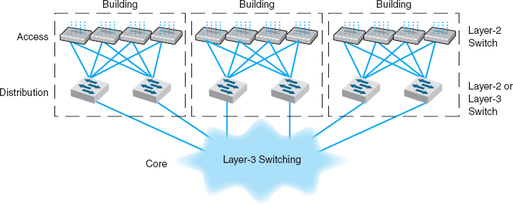
FIGURE 7.14 The best practice network design
7.1 MULTIPROTOCOL LABEL SWITCHING
TECHNICAL FOCUS
Multiprotocol Label Switching (MPLS) is an approach to improving QoS and the movement of packets with different layer-2 protocols through TCP/IP networks.
With MPLS, routers called Label Switched Routers (LSRs) are used. The network manager defines a series of Forwarding Equivalence Classes (FEC) through the network of LSRs. Each FEC has a reserved data rate and a QoS.
When a packet arrives at the edge of the MPLS network, an edge LSR reads the destination address on the incoming packet. The edge LSR can be configured to use the IP address, the IP address and the source or destination port, or the address in any protocol understood by the LSR. The edge LSR accepts the incoming packet and attaches an MPLS label (a packet that contains the FEC address). The edge LSR then forwards the packet to the next LSR as defined in the FEC.
This LSR reads the MPLS label and removes it from the incoming packet, consults its MPLS address table to find the packet's next destination, attaches a new MPLS label with the new FEC address, and forwards the packet to the next LSR in the FEC.
This process continues until the packet reaches the edge LSR closest to its final destination. This edge LSR strips off the MPLS label and forwards the packet outside of the MPLS network in exactly the same format in which it entered the MPLS network.
The advantage of MPLS is that it can easily integrate layer-2 protocols and also provide QoS in an IP environment. It also enables traffic management by enabling the network manager to specify FEC based on both the IP address and the source or destination port.
7.5 IMPROVING BACKBONE PERFORMANCE
The method for improving the performance of BNs is similar to that for improving LAN performance. First, find the bottleneck, then solve it (or, more accurately, move the bottleneck somewhere else). You can improve the performance of the network by improving the performance of the computers and other devices in the network, by upgrading the circuits between computers, and by changing the demand placed on the network (Figure 7.15).
7.5.1 Improving Computer and Device Performance
The primary functions of computers and devices in BNs are routing and protocol translations. If the devices and computers are the bottleneck, routing can be improved with faster devices or a faster routing protocol. Distance vector routing is faster than dynamic routing (see Chapter 5) but obviously can impair circuit performance in high-traffic situations. Link state routing is usually used in WANs and MANs because there are many possible routes through the network. BNs often have only a few routes through the network, so link state routing may not be too helpful since it will delay processing and increase the network traffic because of the status reports sent through the network. Distance vector routing will often simplify processing and improve performance.
Most backbone devices are store-and-forward devices. One simple way to improve performance is to ensure that they have sufficient memory. If they don't, the devices will lose packets, requiring them to be retransmitted.
7.5.2 Improving Circuit Capacity
If network circuits are the bottlenecks, there are several options. One is to increase overall circuit capacity (e.g., by going from 100Base-T Ethernet to gigabit Ethernet). Another option is to add additional circuits alongside heavily used ones so that there are several circuits between some devices.
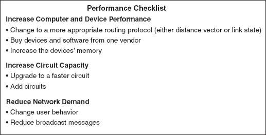
FIGURE 7.15 Improving backbone network performance
In many cases, the bottleneck on the circuit is only in one place—the circuit to the server. A switched network that provides 100 Mbps to the client computers but a faster circuit to the server (e.g., 1000Base-T) can improve performance at very little cost.
7.5.3 Reducing Network Demand
One way to reduce network demand is to restrict applications that use a lot of network capacity, such as desktop videoconferencing, medical imaging, or multimedia. In practice, it is often difficult to restrict users. Nonetheless, finding one application that places a large demand on the network and moving it can have a significant impact.
Much network demand is caused by broadcast messages, such as those used to find data link layer addresses (see Chapter 5). Some application software packages and NOS modules written for use on LANs also use broadcast messages to send status information to all computers on the LAN. For example, broadcast messages inform users when printers are out of paper, or when the server is running low on disk space. When used in a LAN, such messages place little extra demand on the network because every computer on the LAN gets every message.
This is not the case for routed backbones because messages do not normally flow to all computers, but broadcast messages can consume a fair amount of network capacity in switched backbones. In many cases, broadcast messages have little value outside their individual LAN. Therefore, some switches and routers can be set to filter broadcast messages so that they do not go to other networks. This reduces network traffic and improves performance.
7.6 IMPLICATIONS FOR MANAGEMENT
As the technologies used in LANS and WLANs become faster and better, the amount of traffic the backbone network needs to support is increasing at an even faster rate. Coupled with the significant changes in the best practice recommendations for the design of backbone networks, this means that many organizations have had to replace their backbones completely. We would like to think that these have been one-time expenditures, but, as traffic grows, demand placed on the backbone will continue to increase meaning the amount spent on switches and routers for use in the backbone will increase. Designing backbone networks to be easily upgradable is now an important management goal.
As recently as five years ago, ATM was seen as a viable technology for use in backbone networks (ATM is discussed in the next chapter). Today, however, it is clear that Ethernet has beaten ATM as the best backbone technology and ATM is now a legacy backbone technology: no new backbone networks will be installed using it and most vendors have stopped the development of ATM for backbone networks.
As Ethernet moves more extensively into the backbone, the costs associated with buying and maintaining backbone devices and training networking staff will decrease, since now there will be one standard technology in use throughout the LAN, WLAN, and backbone. The new focus is on faster and faster versions of Ethernet. While we will spend more on new equipment, performance will increase much more quickly, and the cost to operate the equipment will decrease.
SUMMARY
Network Components There are two basic components to a BN: the network cable and the hardware devices that connect other networks to the backbone. The cable is essentially the same as those used in LANs, except that it is usually fiber optic to provide higher data rates. The hardware devices include routers, gateways, and switches. Switches connect two LAN segments that use the same data link and network protocol and forward only those messages that need to go to other network segments. Routers connect two or more LANs that use the same or different data link protocols but employ the same network protocol. Gateways connect two or more LANs that use the same or different data link and network protocols (usually different). Layer-2 switches are similar to bridges, whereas layer-3 switches are similar to routers.
Backbone Architectures Network designers often think about three distinct technology layers when designing backbones. The access layer is the LAN, the distribution layer connects the LANs together, and the core layer connects the distribution-layer BNs together. The distribution layer is usually a backbone within a building, whereas the core layer often connects buildings and is sometimes called the campus network. A routed backbone uses a set of routers or layer-3 switches to connect LANs together and moves messages using layer-3 addresses. A switched backbone uses one device, usually a layer-2 switch, to connect the LANs. A VLAN uses layer-2 or layer-3 switches to build logical or virtual LANs that enable the network manager to assign capacity separate from physical location.
Best Practice Backbone Design The best practice backbone architecture for most organizations is a switched backbone (using a rack or a chassis switch) or VLAN in the distribution layer and a routed backbone in the core layer. The recommended technology is gigabit Ethernet.
Improving Backbone Performance Backbone performance can be improved by choosing the best network layer routing protocols. Upgrading to faster circuits and adding additional circuits on very busy backbones can also improve performance. Finally, one could move servers closer to the end users or reduce broadcast traffic to reduce backbone traffic.
KEY TERMS
access layer
backbone network (BN)
campus network
chassis switch
core layer
distribution layer
enterprise network
forwarding equivalence class (FEC)
gateways
IEEE 802.1q
label switched router (LSR)
layer-2 switch
layer-3 switch
main distribution facility (MDF) module
multiprotocol label switching (MPLS)
multiswitch VLAN
patch cables
rack
routed backbone
router
single-switch VLAN
switched backbone
virtual LAN (VLAN)
VLAN ID
VLAN tag
VLAN trunk
QUESTIONS
- Compare and contrast switches, routers, and gateways.
- How does a layer-2 switch differ from a layer-3 switch?
- How does a router differ from a layer-3 switch?
- Under what circumstances would you want to use a router?
- What is an enterprise network?
- What are the three technology layers important in backbone design?
- Explain how routed backbones work.
- Where are routed backbones most commonly used?
- Explain how switched backbones work.
- What are the key advantages and disadvantages of routed and switched backbones?
- Compare and contrast rack-based and chassis-based switched backbones.
- What is a module and why are modules important?
- Explain how single-switch VLANs work.
- Explain how multiswitch VLANs work.
- What is IEEE 802.1q?
- What are the advantages and disadvantages of VLANs?
- How can you improve the performance of a BN?
- Why are broadcast messages important?
- What are the preferred architectures used in the technology layers in backbone design?
- Some experts are predicting that Ethernet will move into the WAN. What do you think?
EXERCISES
7-1. Survey the BNs used in your organization. Do they use Ethernet or some other technology? Why?
7-2. Document one BN in detail. What devices are attached, what cabling is used, and what is the topology? What networks does the backbone connect?
7-3. You have been hired by a small company to install a backbone to connect four 100base-T Ethernet LANs (each using one 24-port hub) and to provide a connection to the Internet. Develop a simple backbone and determine the total cost (i.e., select the backbone technology and price it, select the cabling and price it, select the devices and price them, and so on). Prices are available at www.datacommwarehouse.com, but use any source that is convenient. For simplicity, assume that category 5, category 5e, category 6, and fiber-optic cable have a fixed cost per circuit to buy and install, regardless of distance, of $50, $60, $120, and $300, respectively.
MINI-CASES
I. Pat's Engineering Works
Pat's Engineering Works is a small company that specializes in complex engineering consulting projects. The projects typically involve one or two engineers who do data intensive analyses for companies. Because so much data are needed, the projects are stored on the company's high-capacity server but moved to the engineers’ workstations for analysis. The company is moving into new offices and wants you to design its network. It has a staff of 8 engineers (which is expected to grow to 12 over the next 5 years), plus another 8 management and clerical employees who also need network connections but whose needs are less intense. Design the network. Be sure to include a diagram.
II. Hospitality Hotel
Hospitality Hotel is a luxury hotel whose guests are mostly business travelers. To improve its quality of service, it has decided to install network connections in each of its 600 guest rooms and 12 conference meeting rooms. Last year, the hotel upgraded its own internal networks to switched 100Base-T, but it wants to keep the public network (i.e., the guest and meeting rooms) separate from its private network (i.e., its own computer systems). Your task is to design the public network and decide how to connect the two networks together. Be sure to include a diagram.
Reread Management Focus 7.1. What other alternatives do you think that Indiana University considered? Why do you think they did what they did?
IV. Shangi-La
Reread Management Focus 7.2. What other alternatives do you think that the Shangri-La Resort considered? Why do you think they did what they did?
V. Western Trucking
Western Trucking operates a large fleet of trucks that deliver shipments for commercial shippers such as food stores, retailers, and wholesalers. Their main headquarters building and secondary building are shown in Figure 7.16. They currently have a mix of shared 10base-T and switched 10base-T LANs, connected by a series of switches. They want to upgrade to a faster network. Design a new network for them, including the architecture and specific backbone and LAN technologies to be used.
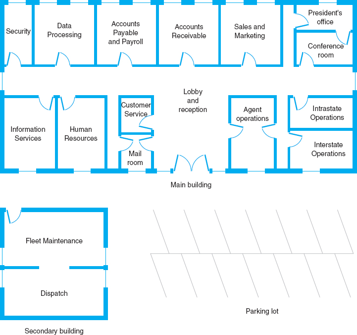
FIGURE 7.16 Facility map of the Western Trucking headquarters
HANDS-ON ACTIVITY 7A
Network Mapping
A backbone network connects one or more LANs to each other and usually to the Internet or to another backbone that eventually leads to the Internet. Each of these backbones usually connects many computers.
Network mapping software enables you to generate a map of the computers on all the LANs connected to a backbone. There are many good network mapping packages. Two of my favorites are LANState and LAN Surveyor. LANState is simpler to use but works best for small networks. LAN Surveyor is more complex, but can map large networks.
Both work in the same way. They use the ping command (see Chapter 5) to send IMCP requests to all possible IP addresses in any range you specify. Any computer that responds is added to the map.
Mapping a Small Network
The first step is to download and install LANState. A demo version of the software is available free of charge from 10-Strike Software (www.10-strike.com/lanstate).
You begin by creating a new network map (choose File Create). Then use the Network Map Creation Wizard and choose to Scan an IP-address range. You will be asked to enter an address range. Choose some range, ideally the address range of a small network. I choose to use my home network range (192.168.1.1 through 192.168.1.254). When the scan is complete you will see a list of computers. Click Finish to see a map of these computers.
LANState does not do a good job of drawing a map, but you can rearrange the computers by dragging and dropping them. You can also add lines to make the map look more like a network diagram. Figure 7.17 shows the small network in my house. I have a router (192.168.1.1) that connects a number of computers to the Internet. I also have a wireless access point (192.168.1.100) and a music server (192.168.1.52). When I did this map, three computers were turned on and responded to LANState's pings (192.168.1.102, 192.168.1.103, 192.168.1.111). Computers and devices that are not turned on do not respond to the pings and therefore are not mapped. Since I use dynamic addressing, the addresses of my computers will change every time I turn them on.
You can also left click on any device and choose System Information and General to learn more about that device. Figure 7.17 also shows the information about my son's computer (192.168.1.103). It shows the MAC address (i.e., the Ethernet address), the card manufacturer, and Windows workgroup peer-to-peer network information (i.e., application layer address) for this computer.
Mapping a Large Network
The first step is to download and install LAN Surveyor. A demo version of the software is available free of charge from Solarwinds (www.solarwinds.com/products/lansurveyor). Installing the software and setting it up to run is more complex, so be sure to follow the setup and configuration instructions.
You begin by creating a new network map (choose File New). You will be asked to enter an address range. Choose some range, ideally the address range of a large network. I choose to use part of the Indiana University network (129.79.1.1 through 129.79.1.254). There is no rule preventing you from scanning anyone's network, but many companies (and individuals) feel that scanning their networks is an invasion of privacy, so scan carefully. When the scan is complete, you will see a map of computers.
My scan of this one small part of the Indiana University network found 124 computers. Figure 7.18 shows a partial list of the computers and their IP addresses and host names (i.e., application layer addresses).
Deliverables
- Use the 10-Strike Software to draw a map of you home network. Describe each component on your map just like the example in the textbook shows.
- Use the System Information and provide additional information (e.g., MAC address, card manufacturer) about at least two devices on your network.
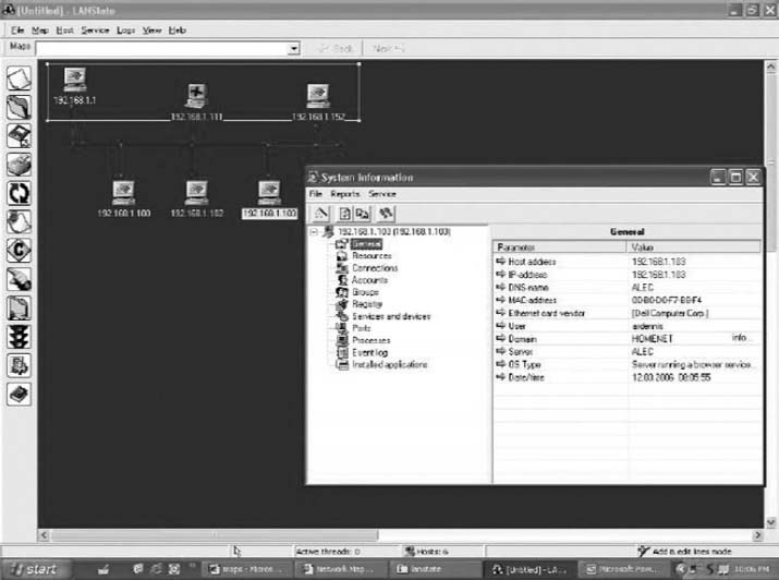
FIGURE 7.17 Network mapping with LANState
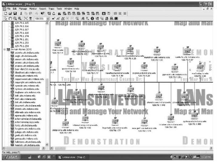
FIGURE 7.18 Network mapping with LAN Surveyor
1 Try not to confuse the five basic layers in the network model (application layer, transport layer, and so on) with the layers of backbone technology we are describing here. They are different. We would have preferred to use a different word than layer to describe these, but unfortunately, that is the term used in the industry.
2 One type of VLAN switches used to enable computers to be assigned into VLANs is based on dynamic criteria such as their Ethernet address, but this type of switch has essentially disappeared. The extra cost of dynamic VLAN switches outweighed the benefits they provided and they lost in the marketplace.