Chapter 4
Creating your own 3D Model
Beginning Modeling Tools
If you are new to 3D modeling, it may seem a bit overwhelming at first. Overcoming the hurdles of learning a new program may feel daunting and make 3D printing your own creations a bit out of reach.
Thankfully more and more fun beginner programs are starting to emerge to help take the fear out of your first 3D model. These programs can act as stepping-stones into the world of modeling. They are usually free, non-threatening, simplified versions with user-friendly functionality. Additionally, the internet is full of 3D printing applications for children, like Crayon Creatures that turns childrens’ drawings into 3D printed figurines or Cookie Caster for building custom cookie cutters from existing images (see Figures 4.2a–b).


Figure 4.2a Crayon Creatures, a project by cunicode.com. Designer: Bernat Cuni.
Photo courtesy of: Bernat Cuni

Figure 4.2b
Screenshot of CookieCaster.com
A Few Beginning Modeling Programs:
-
Cubify Draw
Convert your own doodles into 3D printed objects (see Figure 4.3).
-
MakerBot PrintShop
Alter existing shapes in a number of ways to create your own unique item (see Figure 4.4).

Figure 4.3 Cubify Draw screenshot.

Figure 4.4 MakerBot PrintShop screenshot.
-
Autodesk Project Shapeshifter
Modify basic shapes into 3D printable items (see Figure 4.5).

Figure 4.5 Project Shapeshifter screenshot.
-
Shapeways 2D to 3D Creator
Create a 3D object from a simple hand-drawn Sharpie sketch (see Figures 4.6a–b).
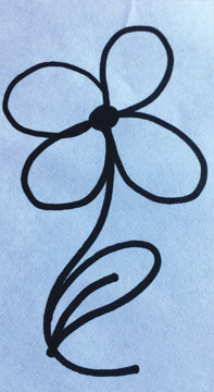
Figure 4.6a Hand-drawn Sharpie sketch.

Figure 4.6b 2D to 3D Creator screenshot.
-
Customizable 3D printed figurines just for fun (see Figure 4.7).

Figure 4.7 Mixee Me screenshot.
3D Modeling Programs
Once you are ready to jump into more advanced programs, there is an array from which to choose. Essentially any program that can export to a 3D file type can be used for 3D printing, you just need to choose the one in which you feel most comfortable.
In general, 3D modeling programs are divided into five categories: solid modeling (or box modeling), sculpting modeling (or digital sculpting), polygonal modeling (or contour modeling), parametric design (or procedural modeling), and vector-graphic design (or curve and line modeling) programs, although some programs may be a hybrid of techniques.
You may find that you choose to alternate between programs depending upon the application. For example, a vector-graphic program (like Vectorworks) may be easiest for something structural, like a model chair, while a sculpting program (like Meshmixer) may be best suited for more organically shaped objects, like a marionette face.
“For new users I recommend keeping things simple. If you can subdivide, subdivide. For example, for modeling a Corinthian column we modeled only a quarter of the capital instead of the entire thing. We took special care to assure that it would line up with its mirror image in both directions. Cutting your object into the smallest section possible helps a lot.”
Colin McGurk, scenic designer
Some popular software programs used for 3D modeling:
Solid Modeling Programs
- SketchUp
- Autodesk Inventor
- Tinkercad
- Cubify Invent
- SolidWorks
- 3DCrafter
- Fusion 360
Polygonal Modeling Programs
- Blender
- 3ds Max
- Maya
- MODO
- Lightwave 3D
- Rhino 3D
Vector-Graphic Design Programs
- Vectorworks
- AutoCAD
- TurboCAD
Sculpting Modeling Programs
- ZBrush
- Sculptris
- Mudbox
- Cubify Sculpt
- Meshmixer
- Geomagic Freeform
Parametric Design Programs
- OpenSCAD
- FreeCAD
Solid Modeling
Solid modeling programs use a technique called constructive solid geometry, which employs simple “primitive” shapes (like cubes, cylinders, and pyramids) as a starting point for complex shapes (see Figure 4.8). They also inherently address the issue of manifold integrity or “watertightness” (discussed later in this chapter) – a property imperative for a successful 3D print.

Figure 4.8
Sample primitive shapes.
Solid modeling programs are considered the most user-friendly of the 3D applications and can be a great place for first-time users to begin. These programs also allow precise measurements to be set for sizing and spacing, which is useful for scale models.
Sculpting Modeling
Sculpting modeling programs emulate the real-world process of modeling with clay. The user can tug, twist, squish, and manipulate a lump of virtual clay in a natural, free-form way (see Figure 4.9). Combining this software with the use of a haptic 3D stylus enhances the experience even further; this specialized stylus allows the user to feel simulated resistance from the virtual piece of clay.
Precise measurements and flat surfaces are typically not possible with this type of software. Due to its organic nature, sculpting modeling programs may be ideal for things like puppet faces and sculptural costume accents.

Figure 4.9 Sculpting modeling program screenshot – Meshmixer by Autodesk.
Polygonal Modeling
Polygonal modeling programs use a surface mesh – a collection of vertices, edges, and faces – to define the shape of a 3D object (see Figure 4.10). These complex programs often have a steeper learning curve and may be better suited for non-printing industries, such as computer graphics and animation.

Figure 4.10
Mesh displayed in Autodesk’s 3ds Max. Veggie Bird™ character designed and created by Mulvaney Studios.
Image courtesy of: Jonathan Mulvaney
Part of the reason that polygonal modeling programs may not be ideal for 3D printing is that they create surface models, as opposed to solid models (which the previously mentioned programs create). Surface models consist of a surface mesh only (like a virtual skin) while solid models produce a fully solid and watertight object, which is ideal for 3D printing. When manipulating surface models, it may be difficult to keep all the polygons and vertices connected so that the model remains solid and, therefore, more likely printable.
If you prefer to model in a polygonal program, running your model through an additional fixing program may increase its chances as a successful print (more on fixing programs in the next chapter).
Parametric Design
Parametric design programs think in a completely different way than the three aforementioned types of modeling programs. Instead of drawing and manipulating shapes with a mouse, objects are created by defining parameters of a shape, like a dimension, by way of a scripting language. The advantage to this is that items with precise dimensions can be quickly created.

Figure 4.11 Convolution Bangle created with parametric modeling by Nervous System (http://nervo.us). Designed by: Jessica Rosenkrantz and Jesse Louis-Rosenberg.
Photo by: Jessica Rosenkrantz
Some artists have used parametric programs to create complex, abstract art forms from mathematical formulas. Through unexpected results, models have been created that would be nearly impossible to create by hand (see Figure 4.11).
Vector-Graphic Design
Vector-graphic design programs (also known as vector-based or object-based editing software) use points, lines, curves, and polygons to represent an image. Objects drawn in 2D must be converted to 3D before exporting to STL.
Although programs such as Vectorworks and AutoCAD have begun to adopt solid modeling features, one major distinction of a vector-graphic program is that Boolean operations do not happen automatically. A Boolean operation is a function that combines separate items together into one object – such as combining two intersecting cubes into one solid object. In a vector-graphic program those cubes must be added together or intersected in some way to form a solid object. The results are the same as a Boolean function, but vector-graphic programs add that extra step. This can be a blessing or a curse; automatic Boolean operations make creations simpler and faster but altering objects later may be more difficult.
Some simple tutorials using Vectorworks can be found in Part III of this text.
“3D printing makes me think of design in new ways – like the crazy Frank Gehry-like shapes that you can come up with fairly easily in a 3D drafting program and just print out. In the past I would have done stuff like that, but I would have been taking paper and cardboard and trying to bend them into shapes and making them do things a flat surface doesn’t naturally want to do. Or, honestly, just taking a chair and warping it digitally and then printing that. I do a fair amount of forced perspective. For things like that, ultimately, 3D printing is a huge boon.”
Beowulf Boritt, Broadway scenic designer
Design Considerations
“The more planning that I do in advance, the less amount of time I spend printing.”
David J. Castellano, scenic designer
Once you decide what program you want to use and what object you want to model, you must then consider (in advance) how well it may print or not, and what method of 3D printing you plan to use – each process has slightly different design constraints (see Figure 4.12).
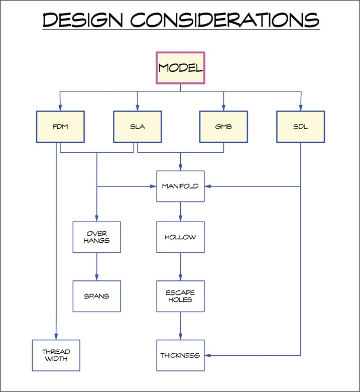
Figure 4.12
Design considerations overview.
“Before you set out to design a bookcase, you make choices. What materials will I use? What tools do I have available? If you want a bookcase out of steel & glass, you will design it very differently than if you want to make a bookshelf from particle board & veneer. Your tools and materials dictate your design choices. The same is true with 3D printing. Choose your tools and materials, then design an object that can be built well with your chosen technology.”
Kacie Hultgren, scenic designer
Overhangs
Overhangs, or unsupported features, are difficult to print with FDM and SLA machines. Think of building a sandcastle: you can build a pyramid-shaped or cylindrical sandcastle easily, but if you want a castle with a large balcony on its side it must be supported from below to keep the balcony from falling down (see Figure 4.13). Extreme overhangs like this become droopy or may not print at all (see Figure 4.14). To avoid problems like this with your prints, unsupported overhangs should not extend past 45 degrees (see Figures 4.15a–b). This is referred to as the 45-degree rule (see Figure 4.16).

Figure 4.13
Overhangs, sandcastle example.

Figure 4.14 Droopy printing due to excessive overhang.
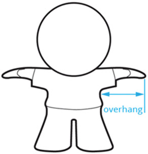


Figure 4.16 45-degree rule.
Bridges
Bridges – “sections of a print that are supported at both ends, but not in the middle”14 – can act much like an overhang and can be difficult to print using FDM and SLA; too much of a span may cause FDM filament to droop or fail completely (see Figure 4.17). For example, a 1/2” scale sofa seat may have trouble bridging the long length between each leg, but a 1/4” one may print without issue.

Figure 4.17
Droopy chair bridge.
There are five common ways to handle printing with overhangs, bridges, and other unsupported features using an FDM printer:
- Revise the model to avoid extreme overhangs or bridges. Figure 4.18 shows a simple flip of geometry to make the angles of an overhang more printer-friendly. Alternatively, the angle of the flag overhang could have been made less severe in its original orientation.

Figure 4.18 Revised geometry to avoid overhangs.
- Print using temporary supports provided by your modeling or printing software (see Figure 4.19). More on supports in Chapter 6.

Figure 4.19 Sheep with temporary supports created by software.
- Design custom temporary supports into your model that can be broken away later (see Figure 4.20). Designing your own supports may use less material and cause less blemishes on the final product than ones provided by your software. Cones or small rods often make good custom supports because their small surface area can be easily snapped off post-print without too much damage to the final object.

Figure 4.20 Custom cone supports for overhang.
- Orient the print so that unsupported features lay flat and are supported by the build plate (see Figure 4.21).

Figure 4.21 Model chair printed on its back to avoid overhang issues from seat and chair back. Small custom supports have been added for legs.
- Separate the model into several pieces so that unsupported features are not an issue (see Figure 4.22).
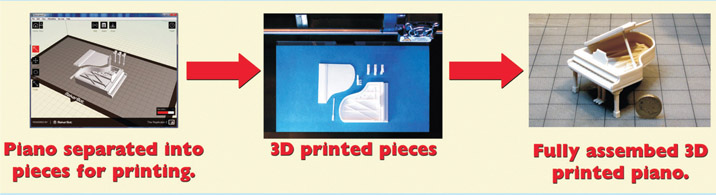
Figure 4.22 Model piano printed in pieces to avoid overhangs. Photos courtesy of: Colin Winslow
Thread Width
The successful printing of very fine details on FDM machines depends on the diameter of your printer’s nozzle. Nozzle size determines the printer’s thread width, or the width of a single thread of deposited filament: typically, 0.4mm or 0.5mm wide.
Consider your printer’s thread width when designing small details into your object. For example, thin circular features, such as balusters on a model staircase or spindles on the back of a model chair, can only be as small as one printed circle of filament (or twice the thread width) (see Figures 4.23a–b).
“Thin features need to be at least two thread widths (think: drawing a circle) but may need to be slightly larger to be sturdy – a short, thin feature may be able to print with a .9mm diameter, while a taller feature [may] need a wider diameter 1.2–2mm to be sturdy.”
Kacie Hultgren, scenic designer
Thread width can also be used as an advantage. Hultgren suggests, “If you are making flexible models or need very thin features, design [items] to be one thread width thick.”15 Not only can you create objects with some bend in them, but using a double thread width for the thickness of your model walls will save print time by not requiring infill.
For more examples on utilizing this technique, check out Hultgren’s collection of “Flexible Inspiration” models on Thingiverse: www.thingiverse.com/prettysmallthings/collections/flexible-inspiration

Figure 4.23a 3D printed model staircase with intricate turned balusters.
Photo courtesy of: Kacie Hultgren

Figure 4.23b
Thread width and fine details. Windsor chair designed by Kacie Hultgren; thing: 21999 (right).
Photo (left) courtesy of: Jérémie Francois, tridimake.com. Photo (right) by Author
Also, visit Hultgren’s “Designed for Thread Widths” collection: www.thingiverse.com/prettysmallthings/collections/designed-for-thread-widths
Manifold
If there is one most vital design consideration for 3D printing, it would be the issue of manifold integrity. Printed objects must be completely closed and solid; your model must not have any holes or open spaces in its mesh (its surface). This is called manifold or “watertight.” Having a manifold model enables the printing software to understand what is the inside and what is the outside of a model in order to comprehend how to print the object properly.
Any intended holes in the object must have surrounding wall thickness. For example, a doughnut or inner tube shape can be printed, but an object with a simple hole or break in its surface plane cannot (see Figure 4.24). It must be as if you can fill the inside of your model with water and there would not be any leaks.
Non-manifold red flags can be as simple as two parts or faces that appear to touch but actually do not connect. It may also be two surfaces that intersect, which can confuse the software’s understanding of a single surface.
Fixing programs (discussed in Chapter 5) are one of the best ways to determine if your model is manifold. These programs have built-in tools that inspect your model for any holes or issues that may prevent it from printing correctly.
In advance to using a fixing program, you can check your model by assuring that all surfaces are connected as one object as well as inspecting your model for any reversed normals and extraneous interiors (see page opposite).

Figure 4.24
3D printed objects must be manifold, or watertight. The solid cube (red) is manifold. The center (blue) hollow cube is not manifold because the front plane is missing, causing a hole in its mesh. This can be fixed by adding a surrounding wall thickness to the object (green).
Reversed Normals
Some 3D modeling programs see 3D surface planes as having an inside and an outside. Faces that are turned inside-out are called reversed normals. In order for a model to print correctly on some printers, all faces must be facing outward.
For example, Trimble’s SketchUp displays reversed normals as grey-colored and normal faces as white (see Figure 4.25). In SketchUp flipping faces is as easy as right-clicking on the surface and choosing “reverse faces” for a single surface or “orient faces” for multiple surfaces from the drop-down menu.
Some modeling programs and printers may not register reversed normals at all.

Figure 4.25
Reversed normals show as grey in SketchUp. Lighthouse based on tutorial by Sandeep Singh.
Extraneous Interiors
Similarly, some printers and printing services (see Chapter 6) struggle with extraneous interiors, or non-vital lines and surfaces on the inside of the model. These issues may cause the print to fail entirely or, if able to print, extraneous interiors can weaken the strength of the printed object. They will also lengthen print time because the software will need to calculate (and print) extra unnecessary paths.
Some software programs allow you to view the inside of your model as if in an x-ray machine. For instance, SketchUp has a feature called the section plane tool (see Figure 4.26), and Vectorworks has one called the clip cube (see Figure 4.27). Use tools like these to view the inside of your model and delete any extraneous interiors. Ensure that deleting items on the inside does not destroy any surfaces on the outside. Vectorworks also has a shortcut in the “model” pull-down menu, called “add solids,” which rectifies extraneous interiors without having to view the inside of your model (see Figure 4.28).

Figure 4.26 SketchUp’s section plane tool “x-rays” through Robot Owl™ to look for extraneous interiors.

Figure 4.27
Vectorworks’ clip cube shows extraneous interior.
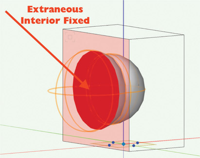
Figure 4.28 Fixed extraneous interior using Vectorworks’ “add solids” command.
Modeling Specialized Items
Some models require an extra step if they have specialized features.
Scale
Consider what scale you want your printed object to be. Two of the most common scales used in the United States for entertainment design are 1/2”=1’-0”(half-inch scale) and 1/4”=1’-0” (quarter-inch scale). If you are creating a scenic model or other scaled item, your finished product will typically be in one of these scales. Prop and costume pieces are usually in full scale (or 1:1).

Figure 4.29
3D printed model furniture in scale.
Photo courtesy of: Kacie Hultgren
The challenge to 3D printing in scale wrestles with two issues: 1) most slicing software and many STL export commands ignore any indication of scale in your original drawing (such as setting your Vectorworks design layers to 1/2” scale); and 2) most 3D printers commonly use metric units.
There are three approaches to drawing in scale with the intention of 3D printing:
- draw the model in full scale then convert to the proper smaller size (that equates to the correct scale) and to metric before exporting to STL,
- draw the model in full scale, export to STL, then convert to scale and to metric units within the slicing software (discussed in Chapter 6), or
- draw the model in metric units and scaled dimensions while in a 1:1 setting before export.
One of the advantages to scaling by approach #3 above is that when drawing in scale there is no question whether or not your model’s finest details will be smaller than the thread width
Try it Out!
As an example, follow the steps below (as in option #1 from the list above) to scale a full-scale model in imperial measurements in Vectorworks.
- Draw your 3D object in real world units at 1:1 scale. For example, a 6’-0” cube would be drawn at an actual 6’-0” in your full-scale drawing (see Figure 4.30a).

Figure 4.30a 6’-0” cube in 1-to-1 scale.
- Scale your model by resizing the object. For 1/2” scale, scale the model by .042. For 1/4” scale, use .021 (see Figure 4.30b). In Vectorworks, this menu is found under the “Modify” pull-down, then “Scale Objects.”

Figure 4.30b Scale Objects dialogue box.
- Finally, convert the units of your drawing to millimeters (if required by your printer) (see Figure 4.30c). In Vectorworks, the “Units” dialogue box is found under “File” then “Document Settings.” The final measurements of your 6’-0” cube in 1/2” scale should be 76.2mm.

Figure 4.30c Units dialogue box.
of your printer. To ease this approach, scenic designer Kacie Hultgren created a series of handy cheat-sheets (see Figures 4.31a–b).
Additionally, an online calculator from Small Stuff’s PrintMini can be found here: www.printmini.com/calc.html (see Figure 4.32).

Figure 4.31a
1/4”=1’-0” scale conversion chart (1-48); thing 22493. Rulers, as printed here, are not to scale.
Image courtesy of: Kacie Hultgren

Figure 4.31b 1/2”=1’-0” scale conversion chart (1-24); thing 22493. Rulers, as printed here, are not to scale.
Image courtesy of: Kacie Hultgren

Figure 4.32 Small Stuff’s PrintMini calculator.
Fit Tolerances

Figure 4.33
Print-in-place working chain; thing: 28405.
3D printed objects can be created in ways that traditional manufacturing cannot replicate; like a chain can be printed in place as all one piece and still be functional (see Figure 4.33). These types of objects are called Print-in-Place Designs. Visit Kacie Hultgren’s Print-in-Place collection for further examples: www.thingiverse.com/prettysmallthings/collections/print-in-place
Print-in-Place Objects


Emmett Lalish’s Secret Heart Box is a great example of a print-in-place object (see Figures 4.34a–b). The box prints all in one piece – complete with working hinges for the lid and a swivel body that transforms the box from a heart to a pill-shape. Spacing between parts (called fit tolerances or gap printing) needs to be precise. “The key to sliding mechanisms is the tolerance between the parts,” says Lalish. “0.4mm … is just right to keep the parts from totally fusing together, but gives a light friction to keep them from moving too easily.”16 Fit tolerances must also account for any shrinkage that may occur during cooling (especially with ABS).
Press Parts
The same holds true for press parts. Press parts are printed hardware pieces used to join separate printed objects together (see Figure 4.35). Press parts can be used to connect the arm and leg joints of a marionette, for example.
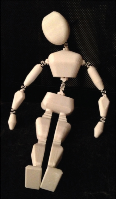
Figure 4.35 Springy Friend designed by Kacie Hultgren, assembled using press parts joints; thing: 17707.
Captive Parts
Captive parts, internal loose structures printed on the inside of a model, are also concerned with fit tolerances. A working whistle with a loose pea inside prints as a captive part (see Figure 4.36a). The pea is attached by one tiny contact point that you must break off (after printing) to roll around loose inside. The cat toy in Figure 4.36b is another example of the same concept – after printing, snap the ball free so Fluffy can play!

Figure 4.36a
Whistle with captive pea; thing: 9206.

Figure 4.36b
Cat toy with captive part; thing: 40407.
“Test your tolerances before you start, so you can plan for success. 0.25mm offset is a tight fit [for press fit parts and connectors]; 0.4mm offset is better for removable parts [and items with a loose fit, such as hinges and box lids].” 17
Kacie Hultgren, scenic designer
Functionality
If the printed piece is going to be mounted on a wall, create holes in the model for hanging hardware. Most 3D printed materials split when screws are inserted (much like Plexiglass) so plan for installation ahead of time in order to ensure the object’s structural integrity.
Similarly for scenic models, consider how the pieces are mounted in the model box. “For example, if modeling a flown piece or hanger, make sure to incorporate pre-drilled holes in the object to allow the brass or piano wire to easily insert and glue to an actual surface,” advises scenic designer Steven C. Kemp (see Figure 4.37). “It’s always helpful when you can think ahead in those regards – especially on a chandelier or other really fragile element that may be difficult to glue something to.”

Figure 4.37
1/4” model with printed translucent lanterns, Madama Butterfly. Black details added with a felt-tip marker.
Photo courtesy of: Steven C. Kemp
Extrusion Type
A multi-extrusion object is made up of separate entities intended for printing in different colors or materials that exactly align, but do not intersect or overlap. Each part of the model must be extruded as separate, manifold STL files, but aligned in the printer software to print as one object. This tutorial gives a basic idea of the needs of modeling for dual-extrusion: https://youtu.be/_1giymE4iXI