
CONTENTS
9.2.1 Conductor Considerations
9.2.2 Conductor with Single Layer of Insulation
9.2.2.1 Underground Residential Distribution Secondary and Similar Designs
9.2.2.2 Thermoplastic Polyvinyl Chloride Wire Recognized by the NEC
9.2.3 Conductor with Insulation and Jacket Layer
9.2.3.1 Jacket to Add Toughness
9.2.3.2 Jacket to Add Toughness, Sunlight, and Flame Resistance
9.2.3.3 Polyvinyl Chloride Jacket to Add sunlight and Flame Resistance
9.2.3.4 Low Smoke Zero Halogen Jacket to Maximize Escape Potential
9.2.4 Plexed Single Conductor Wires and Cables
9.2.5.1 Flat Configuration Multiconductor Cables
9.2.5.2 Round Configuration Multiconductor Cables
9.2.5.3 Low voltage Armored Cables
9.2.5.4 Shielded Low Voltage Cables
While defined differently in Chapter 2, low voltage power cables in this chapter will be those designed to operate at phase-to-phase (VL−L, U) voltages of less than 2 kV. This is done to compensate for some misalignment in standard voltage ratings. In the US standard, rated voltages for low voltage cables are commonly 0 to 600 and 601 to 2,000 volts phase-to-phase (VL−L) based on a grounded “wye” three-phase system (making voltage to ground, Vg = 0.577VL−L). Internationally, a common low voltage rating is 0.6/1 kV, where 1 kV is phase-to-phase (U) and 0.6 kV is phase-to-ground voltage (U0) also based on the same system. There are many exceptions including cables that are rated phase-to-ground. These are generally appropriately marked.
Repeated reference to ICEA [4] and the National Electrical Code (NEC) will be made to US low voltage cables discussed in this chapter. Equivalent (as appropriate) international standards for international designs are given in Chapter 10.
Low voltage power cables might be considered as fully insulated as differentiated from covered cables. They typically have insulation or insulation plus jacket thicknesses (and even armor) that have more to do with mechanical damage and ability to survive the environment in which they will operate than voltage considerations. They operate at voltages low enough that shields (screens) are generally not needed to control voltage stresses but may more likely be used to mitigate the effect of electrostatic and electromagnetic magnetic fields. Despite these common features, they operate in many more applications and environments than higher voltage cables. That results in the need for a very large number of materials and cable designs to meet the needs of the low voltage cable world [7].
One might immediately think of low voltage applications involving electric utility plant or building wires including commercial and industrial applications. However, one quickly must add machine tool wires, cords, appliance wires, oil well cables, transportation and ship board cables, and more, to the subject. The author could not hope to do the entire subject justice. Instead, the chapter will be devoted to presenting some general principles common to designs for numerous applications.
To promote common understanding, it is noted that internationally (and to a declining degree, the US) the word sheath includes both metallic and nonmetallic coverings. In this chapter, nonmetallic coverings will be called “jackets,” and “sheath” will be reserved for metallic coverings.
9.2.1 CONDUCTOR CONSIDERATIONS
Consideration must be given to the required flexibility, conductivity, connectability, and cost of the conductor (Chapter 3), which will result in the selection of conductor material (copper, aluminum, or alloy of either) as well as strand design. Copper conductors are favored where cable diameter, flexibility, connectability of the conductor, and cost of components beyond the conductor are major factors. Aluminum conductors offer cost savings where cable diameter is less of a factor and a weight advantage, which is important for cables suspended in air.
Soft annealed copper is the overwhelming choice when copper conductors are involved. However, aluminum alloys are common when aluminum conductors are involved. As an example, extensive use of screw down connections in indoor plant results in considerable use of 8,000 series aluminum alloy conductors as opposed to 1,350 aluminum commonly used by utilities that favor compression connectors for outdoor plant. This is because 8,000 series alloys have reduced cold flow under pressure. These alloys must also be annealed to achieve an acceptable level of flexibility.
Filled strand conductors are common to block the passage of water longitudinally in navel and/or marine and similar applications or the passage of gasses in special application cables.
9.2.2 CONDUCTOR WITH SINGLE LAYER OF INSULATION
The simplest low voltage cable consists of a single conductor having a single extruded layer of insulation applied over the conductor (Figure 9.1). Insulation material must be sufficiently insulating, sufficiently rugged to withstand the rigors of installation and operation, and have properties that are suitable for the application.
Commonly used single layer insulations include thermoplastic polyvinyl chloride (PVC), polyethylene, and a number of fluoropolymers for special purpose wiring (generally in sizes 4/0 AWG and smaller). Thermoset insulations for single layer applications include cross-linked polyethylene (XLPE) and ethylene–propylene rubber (EPR) with lesser use of materials such as chlorosulfonated polyethylene (CSPE) and irradiated PVC.
Consideration must be given as to whether the insulation material will be strippable from the conductor or if there is a chemical incompatibility with the conductor, which might degrade the insulation.
The solution may involve the use of coated conductors such as tinned copper. A common alternative solution is a tape separator over the conductor. The need for separators is certainly not limited to cables with a single extruded layer of insulation.
If a tape separator is used, common practice dictates that it be of a color different from that of the underlying conductor. This minimizes the possibility that installers install a connector over the separator resulting in a very poor connection. A tape separator is shown in Figure 9.2.
Crystalline insulations (such as, but not limited to, polyethylene) have a tendency to develop internal stress due to extrusion and other processing conditions and then “relax” with time. This causes the insulation to shrink along the conductor exposing additional conductor. This is commonly known as shrink back. The degree to which the insulation fills and grips the interstices of stranded conductors can help reduce shrink back. If a separator is used, any grip on the conductor is lost. Careful processing is required to minimize shrink back in this case. It might be noted that solid conductors are also more prone to shrink back.
Cables with a single layer of insulation are widely used as building wires, utility underground, and many other purposes including machine tool wire and appliance wire. Highlighting the importance of this general design will be accomplished by discussing two “groups” that are widely used.
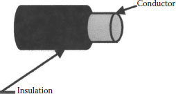
FIGURE 9.1 Conductor with single layer of insulation.
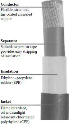
FIGURE 9.2 Typical case of separator. (From Amercable, January 2011, Internet Catalog, with permission. Accessed December 2010.)
9.2.2.1 Underground Residential Distribution Secondary and Similar Designs
Underground residential distribution (URD) electric utility secondary and service cable is most commonly used as an aluminum conductor insulated with a single layer of XLPE. The cable is either directly buried or installed in a duct/conduit. The XLPE is made sunlight-resistant by the incorporation of a low level of carbon black into the XLPE. This low level addition leaves the XLPE with a high voltage breakdown strength greatly exceeding the requirements for a secondary cable and excellent mechanical strength to withstand the rigors of installation and operational conditions common to underground applications. Thus, the XLPE acts as both insulation and jacket. In addition, XLPE is resistant to many chemicals encountered in underground applications. The insulation thickness is a function of conductor size as shown in Table 9.1.
When used for electric utility purposes, the design has a 90°C maximum normal operating temperature. This design is also very popular for applications covered by the NEC [5] for underground service entrance cable (USE). These cables are commonly purchased from distributors by both utilities and contractors. To avoid the need for double inventory, it is common for manufacturers to produce and print the cables as USE even though this would not be a utility requirement for outdoor plant. Indeed, it is not uncommon to see these cables marked USE and used by some utilities as well. When used in NEC applications, the designation given to the design must be considered to determine the temperature rating for both wet and dry applications.
TABLE 9.1
Insulation Thickness as a Function of Conductor size
Conductor size |
USE Insulation Thickness |
XHHW Insulation Thicknes |
||
Awg-kcmils |
Mils |
mm |
Mils |
mm |
12–9 |
45 |
1.14 |
30 |
0.76 |
8–2 |
60 |
1.52 |
45 |
1.14 |
1–4/0 |
80 |
2.03 |
55 |
1.40 |
213–500 |
95 |
2.41 |
65 |
1.65 |
501–1,000 |
110 |
2.79 |
80 |
2.03 |
If formulated to have sufficient flame resistance to pass the required flame tests, the cable might be designated types RHH–RHW and used for indoor plant in accordance with the NEC. However, in that case, if aluminum conductor, an 8,000 series alloy is required and the design is not commonly used by utilities for URD.
The physical toughness and voltage strength of the single layer XLPE cable have made possible a cable design with a lower insulation thickness. This design is commonly installed in a raceway (as defined by the NEC) in accordance with the NEC requirements and conserves raceway internal area required providing cost savings. The design is Type XHHW (heat and moisture resistant synthetic rubber).
Finally, utilities also use thermoplastic polyethylene insulated cable of the same thicknesses as the URD and/or USE cables for lower temperature service. These cables are normally rated for 75°C maximum normal operation. Thus, they are commonly used on more lightly loaded circuits such as street lighting. However, these cables are not generally suitable for NEC applications because of the relatively poorer flame resistance when compared with PVC, which is also a thermoplastic.
9.2.2.2 Thermoplastic Polyvinyl Chloride Wire Recognized by the NEC
NEC types TW, THW, and MTW with no overall jacket are commonly made with a single layer of PVC. They are differentiated from each other by formulation to provide a level of heat resistance, moisture resistance, and oil resistance required by the NEC for the application. One common application is installation in a raceway, such as a conduit. PVC has excellent flame resistance that has made it suitable for many NEC applications. PVC is relatively low cost, easy to process, and lends itself to formulation to maximize specific properties, such as oil resistance, or different colors required for the application. One disadvantage of PVC is that it becomes brittle and subject to impact fracture at lower temperatures, some <15°F depending on formulation. This requires special care in handling at low temperatures. The author is personally aware of incidents where a contractor threw coils of PVC wire off the truck to the ground in cold weather, resulting in cracks in the insulation. In both utility and NEC applications, careful attention must be paid to the type and application of these PVC insulated wires to determine the maximum allowed operating temperature. This can range from 60°C to 90°C.
There are many applications where a single layer of insulation is not adequate. In such cases, it is common to add a jacket over the insulation layer. The purpose of the jacket is to provide one or a number of features the insulation alone cannot provide.
9.2.3 CONDUCTOR WITH INSULATION AND JACKET LAYER
A jacket over the insulation may be used to provide the following (Figure 9.3):
• Physical toughness
• Sunlight resistance
• Chemical resistance
• Flame resistance
• Low smoke release when burning
• Zero halogen release when burning
• Radiation resistance
• Low coefficient of pulling friction
Some examples are discussed in the following section.
9.2.3.1 Jacket to Add Toughness
As discussed in Section 9.2.2, a common underground cable used by utilities and contractors in North America consists of a single layer of polyethylene (75°C normal service) or XLPE (90°C normal service) with carbon black filler to provide sunlight resistance for underground secondary services and services directly buried in earth or in conduit. However, when placed in contact with rubble fill, rocky soils, or soils laden with coral, the damage resistance (impact, cut through, crush and abrasion), is not adequate and the failure rate is elevated. To improve toughness, ruggedized cables are used. The insulation thickness for the single layer cable is partitioned into a thickness of the “original” polyethylene or XLPE insulation overlaid by a thickness of high density polyethylene or medium-to-high density XLPE (insulation/jacket). In the case of the XLPE design, a major challenge is to achieve a truly high density cross-linked outer layer. This is because there are fewer crosslinking sites as the density of the XLPE is increased.
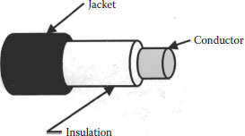
FIGURE 9.3 Single conductor with insulation and jacket.
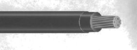
FIGURE 9.4 THHN THWN wire (cable). (From Southwire, January 2011, Internet Catalog, with permission. Accessed December 2010.)
In the US, THHN (heat resistant thermoplastic 90°C normal operation in dry and damp locations) and THWN [heat and moisture resistant thermoplastic 75°C normal operation in wet and dry locations (or 90°C with proper rating)] are NEC designations. The dual rated design with a nylon jacket is tough and has a low pulling coefficient of friction. The toughness of the nylon jacket allows for a reduced total (insulation and jacket) wall thickness and pulling at lower tensions than for the single layer equivalent. This design is widely used for rewiring, often allowing larger conductors to be installed in the existing conduit. A THHN THWN wire (cable) is shown in Figure 9.4.
9.2.3.2 Jacket to Add Toughness, Sunlight, and Flame Resistance
9.2.3.2.1 EPR Insulated Cables
EPR is an excellent low voltage insulation offering many desirable properties. While it can be compounded to provide increased toughness and/or flame resistance, this might compromise the properties for which EPR was selected. It is common to add a jacket of polychloroprene (commonly Neoprene), CSPE (commonly Hypalon), or chlorinated polyethylene (CPE). All three of these materials are relatively tougher than the EPR and as the names imply (chlorinated or chlorine), provide flame resistance. These jackets are also flexible so the cables of this design are widely used where flexibility is a requirement. PVC is also commonly used as a jacket over EPR to add sunlight and flame resistance.
9.2.3.3 Polyvinyl Chloride Jacket to Add sunlight and Flame Resistance
9.2.3.3.1 Polyvinyl Chloride Jacketed Cables
PVC is not considered tough compared with polyethylene or XLPE. However, it is certainly more flame resistant. PVC continues to be used widely over both polyethylene and XLPE as a jacket. The flame resistance and low cost have made PVC a popular jacketing and insulating material. The excellent flame resistance is due to the chlorine in the PVC material. When burned, commonly by an external flame source, the chlorine is released as a gas. Chlorine, when inhaled, can do serious damage to the respiratory system of personnel who are exposed including those escaping a fire or fire fighters engaged in putting it out. Further, methods to put out the fire, such as water, can combine with the chlorine creating an extremely corrosive mixture. The corrosion can cause extensive damage to facilities. This has resulted in increasing use of zero halogen materials for insulation and jackets, especially for indoor plant. However, at this time, PVC continues to be widely used.
9.2.3.4 Low Smoke Zero Halogen Jacket to Maximize Escape Potential
Concern for the epidemiological effects on humans exposed to halogens released by a fire and corrosion consequences has resulted in growing international use of nonhalogenated insulation and jacket materials. However, there has also been concern for the ability of persons involved in, or with a fire, to escape. Smoke release of materials when burning, which might reduce visibility, is now an issue. This has led to increased use of low-smoke zero-halogen (LSZH) materials. LSZH describes a number (rather than single) of families of materials. In addition to the advantages already mentioned, another is reduced soot damage from burning of these materials and there is some reported lower coefficient of friction for LSZH jackets when pulling [2]. Disadvantages reported to date include deterioration of jacket properties when contacted by some pulling compounds and because of high filler loading, poorer mechanical, chemical, and moisture absorption properties may result when compared with non-LSZH jackets.
9.2.4 PLEXED SINGLE CONDUCTOR WIRES AND CABLES
It is very common to apply two, three, four, or more single conductor cables in the same trench, duct, conduit, tray, or other route. Under such circumstance, it is often convenient to produce an assembly of single conductor cables (also called plexed, cabled, or twisted) with no further covering over all. The configuration is commonly named by the number of conductors in the assembly such as: duplex (two conductors), triplex (three conductors), or quadruplex (four conductors) (Figure 9.5).
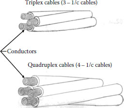
FIGURE 9.5 Triplexed and quadruplexed cables.
Plexing has several advantages. The assembly presents the smallest circumscribing diameter for the cables involved. For single conductor cables of the same diameter, the circumscribing diameter of:
• A duplex assembly is two times the diameter of a single conductor cable
• For a triplex assembly, the multiplier is 2.155
• For a quadruplexed assembly, the multiplier is 2.414
Plexing, which holds the cables together, overcomes some installation issues such as jamming in conduit and ducts, as discussed in Chapter 12. Minimizing the circumscribing diameter also minimizes inductive reactance in AC operation.
Plexing does have a number of disadvantages. Plexing increases the length of the single conductor cable required to make up the plexed assembly length. The increased length results in an increased DC resistance. Maximum cable length on a single reel is reduced, i.e., the length of one single conductor cable on a given reel size is considerably greater than the length of plexed cable of the same size on the same reel.
Multiconductor cables are extensively used in low voltage applications. They may be roughly differentiated from plexed cables as having additional covering layers (metallic shield or armor, nonmetallic jacket, or both) over the assembly. However, many multiconductor cables do not have the individual conductors twisted together but may be laid in parallel (commonly resulting in a flat configuration). Multiconductor cables commonly have additional conductors or components for purposes such as: grounding, check circuit integrity, signal, and/or communication. They also may have binders to hold individual members together and fillers to achieve and maintain a desired shape (such as round).
9.2.5.1 Flat Configuration Multiconductor Cables
Flat configuration cables may simply result as a matter of practical arrangement of the enclosed conductors. For instance, the NM Type cable shown in Figure 9.6 consisting of phase, neutral, and grounding conductor under a common jacket is widely used in the US for residential (but not limited to) wiring in accordance with the NEC. There is no application reason why the cable is flat but it is convenient for the design involved.
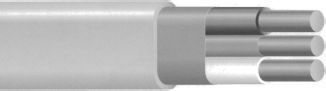
FIGURE 9.6 Type NM cable. (From Southwire, January 2011, Internet Catalog, with permission. Accessed December 2010.)
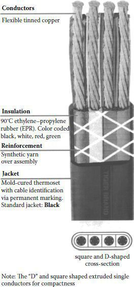
FIGURE 9.7 Type W Flat 4 Conductor Mining Cable, 600/2,000 volt. (From Amercable, January 2011, Internet Catalog, with permission. Accessed December 2010.)
The Type W Flat 4 Conductor Mining Cable shown in Figure 9.7 is subject to reeling and de-reeling while feeding shuttle cars, drills, cutting and loading machines. The flat configuration facilitates bending on the centerline axis through the longer width of the cable. This provides greater flexibility than a four conductor round configuration would. Of course, bending on the other axis would be difficult (and damaging). Attention is called to the extrusion of “D” shaped and square-shaped single conductor members to facilitate a space-saving flat configuration. Thus, in this case, the flat configuration is for a definite purpose. Another example, not shown, would be the Flat Conductor Cable Type FCC designed for installation under carpet squares in accordance with the NEC.
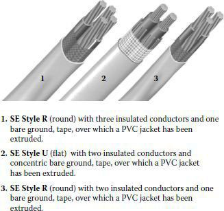
FIGURE 9.8 Service entrance cables. (From Southwire, January 2011, Internet Catalog, with permission. Accessed December 2010.)
Round configuration multiconductor cables are the other (and possibly more) common configuration. Some cable types are made both as flat and round configurations. Service entrance cables are commonly used in the US to bring power from an overhead service drop attached to the building to the meter base and from the meter base to the distribution panel. Service entrance cables may be used in other applications in accordance with the NEC. Figure 9.8 shows a number of available service entrance cables.
9.2.5.2 Round Configuration Multiconductor Cables
There are almost a limitless number of multiconductor cables with a round configuration. With respect to power cables, the most common have three or four insulated power conductors but more are possible for special purpose cables. A simple case might have three insulated conductors and an overall jacket. One such cable typically used for navel shore-to-ship and other pier side power applications is shown in Figure 9.9.
Features not immediately evident from the figure are the red–white–black color coding of the power cables, filling of the interstices at the power cable contacts to minimize water migration, and the reinforcement of the jacket for toughness. In other designs, an interstice might contain a grounding conductor. One, two, or three grounding conductors are common. The number, size, and/or conductivity of the grounding conductors are generally a matter of industry or military specification developed to meet the needs of the application.
ICEA S-95-658/NEMA WC 70 “Standard For Non-shielded Power Cables Rated 2,000 Volts or Less For the Distribution of Electrical Energy” requires that for assemblies of two, three, or four conductor-insulated power cables utilizing a grounding conductor, the minimum grounding conductor size should be as follows unless otherwise specified.
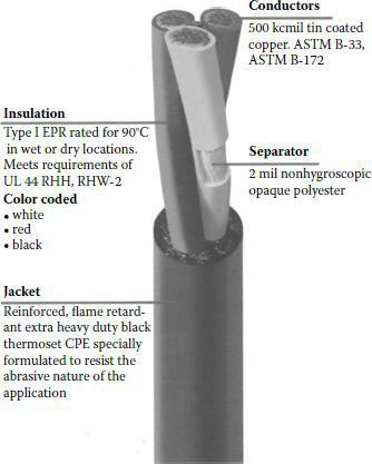
FIGURE 9.9 Three conductor round cable. (From Amercable, January 2011, Internet Catalog, with permission. Accessed December 2010.)
Power Conductor size (AWG or kcmil) |
Grounding Conductor size (AWG or kcmil) |
||
Copper |
Aluminum |
Copper |
Aluminum |
14 |
12 |
14 |
12 |
12 |
10 |
12 |
10 |
10–8 |
8–6 |
10 |
8 |
6–4 |
4–2 |
8 |
6 |
3–2/0 |
1–3/0 |
6 |
4 |
3/0–250 |
4/0–350 |
4 |
2 |
300–400 |
400–600 |
3 |
1 |
450–650 |
700–1,000 |
2 |
1/0 |
700–900 |
— |
1 |
2/0 |
1,000 |
— |
1/0 |
3/0 |
The grounding conductor size may be subdivided into several wires, but no wire shall be less than #18 AWG in size.
Again, the reader is strongly advised to consult the appropriate standard for the cable and application being considered to meet ground wire requirements as they may differ from the above.
The ICEA/NEMA standard also calls for maximum lengths of lay for multiple conductor cables for:
• Multiple conductor assemblies with no overall covering, cabled with a left hand lay, and a maximum length of lay of 60 times the diameter of the largest insulated conductor.
• Multiple conductor round cables with an overall covering with all conductors having the same direction of lay, the lay shall be left hand with a maximum length of lay as shown.
Number of Conductors in Cable |
Maximum Length of Lay |
2 |
30 times individual conductor diameter |
3 |
35 times individual conductor diameter |
4 |
40 times individual conductor diameter |
5 or more |
15 times assembled diameter |
Once again, the governing standard for the cable and application must be consulted as it might not agree with the above.
In Figure 9.10, a design common in international low voltage cables is shown. The underlying insulation may be PVC, XLPE, or EPR overlaid with a PVC jacket. Concern for the safety and health concerns connected with smoke and halogens previously discussed result in increased use of LSZH insulation and jacketing materials internationally. An interesting feature of this design is the use of sector-shaped conductors (120° for 3/C cables and 90° for 4/C cables). Round conductors are also available.
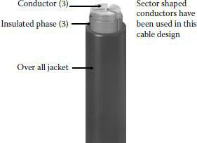
FIGURE 9.10 3/C Low volt cable with sector-shaped conductors. (From General Cable, January 2011, Internet Catalog, with permission. Accessed December 2010.)
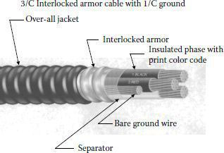
FIGURE 9.11 Interlocked armor low voltage cable. (From Southwire, January 2011, Internet Catalog, with permission. Accessed December 2010.)
9.2.5.3 Low voltage Armored Cables
Cable armoring is discussed in Chapter 8. Armoring of low voltage cables is very common.
The interlocked armor cable shown in Figure 9.11 is in accordance with the NEC in the US. It is listed type MC (metal clad). The armor may be aluminum or galvanized steel and may be bare or jacketed depending on the application. The Type MC cable shown includes ground wires. The NEC also allows inclusion of optical fiber members.
Armoring is discussed in Chapter 8. There are numerous recognized armors. One that might not be thought of immediately is bronze wire braid armor. In Figure 9.12, the armored version of the low voltage cable common internationally (Figure 9.10) is shown. The stark contrast between these two armoring methods shows the diversity to be found in the low voltage cable world.
9.2.5.4 Shielded Low Voltage Cables
In the introduction, it was stated that low voltage cables did not generally require shielding to reduce concentrated electrical stresses that might lead to cable failure. However, low voltage cables might be a source or impacted by electrostatic and electromagnetic field interference (EMI). There are numerous methods to mitigate the interference of such fields. Some may be as simple as to twist the pair of unshielded wires being exposed to the fields. In general, electrostatic fields are more easily shielded against than magnetic fields. The measures needed to deal with magnetic fields are more complex and are frequency dependent. In Figure 9.13, one method of design and shielding to deal with EMI in connection with variable frequency drive applications is shown. Note the emphasis on symmetry of cable components to maximize field cancellation.
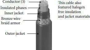
FIGURE 9.12 3/C Armored low volt cable, sector-shaped conductors. (From General Cable, January 2011, Internet Catalog, with permission. Accessed December 2010.)
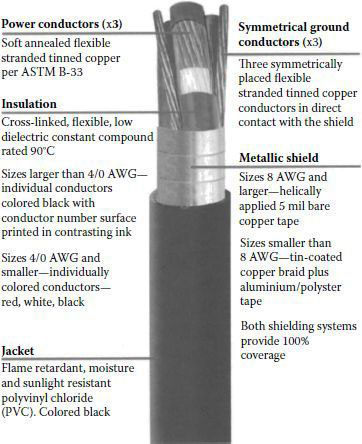
FIGURE 9.13 Shielding low volt cable to contain EMI emissions. (From Amercable, January 2011, Internet Catalog, with permission. Accessed December 2010.)
This is but one example. As a general rule, the lower the frequency, the more difficult it is to provide shielding for magnetic fields. Thick layers of high magnetic permeability metal may be required at low frequencies (such as 60 Hz) while at higher frequency (>1 KHz) copper braid might provide some measure of shielding. The subject is extremely complex and beyond the scope of this chapter.
1. Internet Catalog, January 2011, AmerCable.
2. Wire & Cable Technical Information Handbook, 1996, Anixter.
3. Internet Catalog, January 2011, General Cable.
4. “Power Cables Rated 2000 Volts or Less for the Distribution of Electrical Energy,” 2009, ICEA S-95-658/NEMA WC 70.
5. National Electrical Code, 2005, NFPA 70.
6. Internet Catalog, January 2011, Southwire.
7. “Understanding Power Cable Characteristics and Applications,” 2006, University of Wisconsin–Madison, October 2006, Las Vegas, NV.