
CONTENTS
3.2.1 Direct Current Resistance
3.3.1 American Wire Gauge (AWG)
3.3.1.1 Shortcuts for Estimations
3.7 Physical and Mechanical Properties
3.7.1.3 Comparative properties, Copper versus Aluminum
3.9.5 Cables in Magnetic Metallic Conduit
3.9.6 Resistance at Higher Frequencies
The fundamental concern of power cable engineering is to transmit electrical current (power) economically and efficiently. The choice of the conductor material, size, and design must take into consideration such items as:
• Ampacity (current carrying capacity)
• Voltage stress at the conductor
• Voltage regulation
• Conductor losses
• Bending radius and flexibility
• Overall economics
• Material considerations
• Mechanical properties
There are several low resistivity (or high conductivity) metals that may be used as conductors for power cables. Examples of these as ranked in order of increased resistivity at 20°C are shown in Table 3.1 [1].
Considering these resistivity figures and the cost of each of these materials, copper and aluminum become the logical choices. As such, they are the dominant metals used in the power cable industry today.
When choosing between copper and aluminum conductors, one should carefully compare the properties of the two metals, as each has advantages that may outweigh the other under certain conditions. The properties most important to the cable designer are shown in the following sections.
TABLE 3.1
Resistivity of Metals at 20°C
Metal |
Ohm-mm2/m × 10−8 |
Ohm-cmil/ft × 10−6 |
Silver |
1.629 |
9.80 |
Copper, annealed |
1.724 |
10.371 |
Copper, hard drawn |
1.777 |
10.69 |
Copper, tinned |
1.741–1.814 |
10.47–10.91 |
Aluminum, soft, 61.2% cond. |
2.803 |
16.82 |
Aluminum, 1/2 hard to full hard |
2.828 |
16.946 |
Sodium |
4.3 |
25.87 |
Nickel |
7.8 |
46.9 |
3.2.1 DIRECT CURRENT RESISTANCE
The conductivity of aluminum is about 61.2% to 62.0% of that of copper. Therefore, an aluminum conductor must have a cross-sectional area about 1.6 times that of a copper conductor to have the equivalent DC resistance. This difference in area is approximately equal to two American wire gauge (AWG) sizes.
One of the most important advantages of aluminum, other than economics, is its low density. A unit length of bare aluminum wire weighs only 48% as much as the same length of copper wire having an equivalent DC resistance. However, some of this weight advantage is lost when the conductor is insulated, because more insulation volume is required over the equivalent aluminum wire to cover the greater circumference.
The current carrying capacity (ampacity) of aluminum versus copper conductors can be compared by referring to many documents. See Chapter 14 for details and references, but obviously a larger aluminum cross-sectional area is required to carry the same current as a copper conductor as can be seen from Table 3.1.
In alternating current (AC) circuits having small conductors (up to #2/0 AWG), and in all DC circuits, the effect of reactance is negligible. Equivalent voltage drop results with an aluminum conductor that has about 1.6 times the cross-sectional area of a copper conductor.
In AC circuits having larger conductors, however, skin and proximity effects influence the resistance value (AC to DC ratio, later written as AC/DC ratio), and the effect of reactance becomes important. Under these conditions, the conversion factor drops slightly, reaching a value of approximately 1.4.
Consideration should also be given to possible short circuit conditions, since copper conductors have higher capabilities in short circuit operation. However, when making this comparison, the thermal limits of the materials in contact with the conductor (e.g., shields, insulation, coverings, jackets, etc.) must be considered.
Additional care must be taken when making connections with aluminum conductors. Not only does the metal tend to creep, but it also oxidizes rapidly. When aluminum is exposed to air, a thin, corrosion-resistant, high dielectric strength film quickly forms.
When copper and aluminum conductors are connected together, special techniques are required in order to make a satisfactory connection. See the discussion in Chapter 13.
Aluminum is not used extensively in generating station, substation, or portable cables because the lower bending life of small strands of aluminum does not always meet the mechanical requirements of those cables. Space is frequently a consideration at such locations also. However, aluminum is the overwhelming choice for aerial conductors because of its high conductivity-to-weight ratio and for underground distribution for economy where space is not a consideration.
The 8000 series aluminum alloys have found good acceptance in large commercial, institutional, and some industrial applications. These alloys offer reduced cold flow and improved creep resistance. This offers greater retention of torque at “screw down” terminals commonly used in “indoor plant.” In the US, the National Electrical Code (NEC) calls for the use of these alloys if aluminum is to be used in a number of wire types recognized by the NEC.
Economics of the cost of the two metals must, of course, be considered, but always weighed after the cost of the overlying materials is added.
3.3.1 AMERICAN WIRE GAUGE (AWG)
Just as in any industry, a standard unit must be established for measuring the conductor sizes. In the US and Canada, electrical conductors are sized using the AWG system. This system is based on the following definitions:
• The diameter of size #0000 AWG (usually written #4/0 AWG and said as “four ought”) is 0.4600 inches for a solid conductor.
• The diameter of size #36 AWG is 0.0050 inches.
• There are 38 intermediate sizes governed by a geometric progression.
The ratio of any diameter to that of the next smaller size is:
(3.1) |
3.3.1.1 Shortcuts for Estimations
The square of the above ratio (the ratio of diameters of successive sizes) is 1.2610. Thus, an increase of one AWG size yields a 12.3% increase in diameter and an increase of 26.1% in area. An increase of two AWG sizes results in a change of 1.261 (or 26.1%) in diameter and 59% increase in area.
The sixth power of 1.122932 is 2.0050 or very nearly 2. Therefore, changing six AWG sizes will approximately double (or halve) the diameter. Another useful shortcut is that a #10 AWG wire has a diameter of approximately 0.1 inch, for copper a resistance of 1 ohm per 1,000 feet and a weight of about 10π or 31.4 pounds per 1,000 feet.
Another convenient rule is based on the fact that the tenth power of 1.2610 is 10.164 or approximately 10. Thus, for every increase or decrease of 10 gauge numbers (starting anywhere in the table), the cross-sectional area, resistance, and weight are divided or multiplied by about 10.
From a manufacturing standpoint, the AWG sizes have the convenient property that successive sizes represent approximately one reduction in die size in the wire drawing operation.
The AWG sizes were originally known as the Brown and Sharpe gage (B&S). The Birmingham wire gage (BWG) is used for steel armor wires. In Britain, wire sizes were specified by the standard wire gage (SWG), and were also known as the new British standard (NBS).
Sizes larger than #4/0 AWG are specified in terms of the total cross-sectional area of the conductor and are expressed in circular mils. This method uses an arbitrary area of a conductor that is achieved by squaring the diameter of a solid conductor. This drops the π/4 multiplier required for the actual area of a round conductor. A circular mil is a unit of area equal to the area of a circle having a diameter of 1 mil (1 mil = 0.001 inch). Such a circle has an area of 0.7854 (or π/4) square mils. Thus, a wire 10 mils in diameter has a cross-sectional area of 100 circular mils. Likewise, 1 square inch = 4/π times 1,000,000 = 1,273,000 circular mils. For convenience, this is usually expressed in thousands of circular mils and abbreviated kcmil. Thus, an area of 1 square inch = 1,273 kcmil.
(3.2) |
where A = area in circular mils; π = 3.1416; r = radius in 1/1,000 of an inch.
The abbreviation used in the past for thousand circular mils was MCM. The SI abbreviations for million, M, and for coulombs, C, are easily confused with this older term. Thus, the preferred abbreviation is kcmil for “thousand circular mils.”
The AWG/kcmil system is prevalent in North America (population over 425 million) and is also used to some extent in over 65 countries in the world. The market share of cable products sized with this system is estimated at over 30% ($17.3 billion) of the world market for power and control wires and cables. The AWG/kcmil system is also the reference sizing system for all electrical products and installations in North America. As such it represents a basic element of the infrastructure. When considered in conjunction with wiring devices, connectors, and other related products, the market affected by the AWG/kcmil system is substantially larger [7].
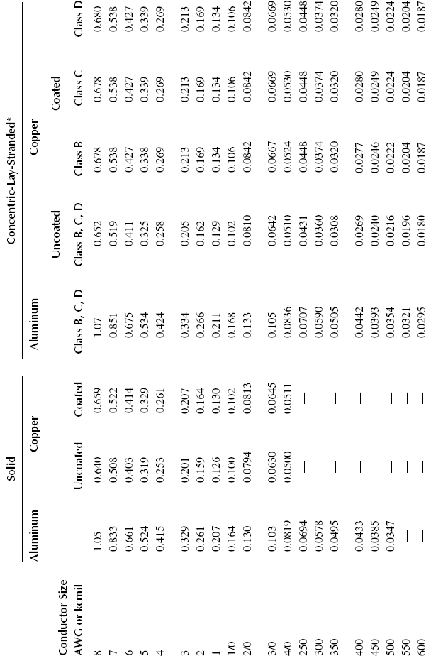
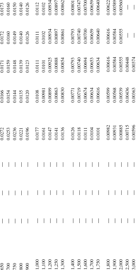
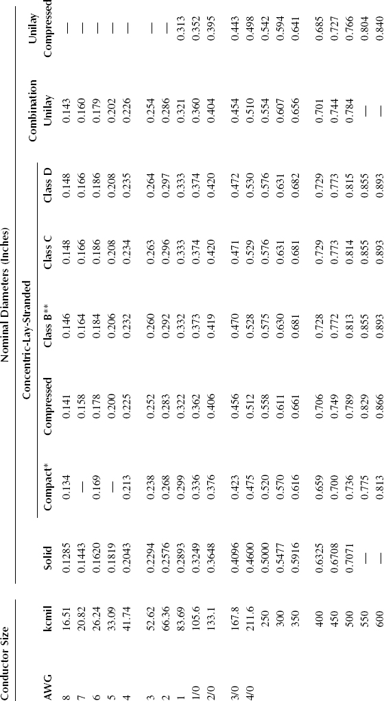
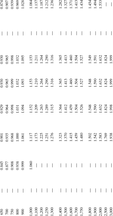
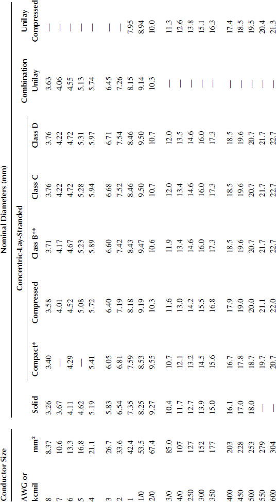
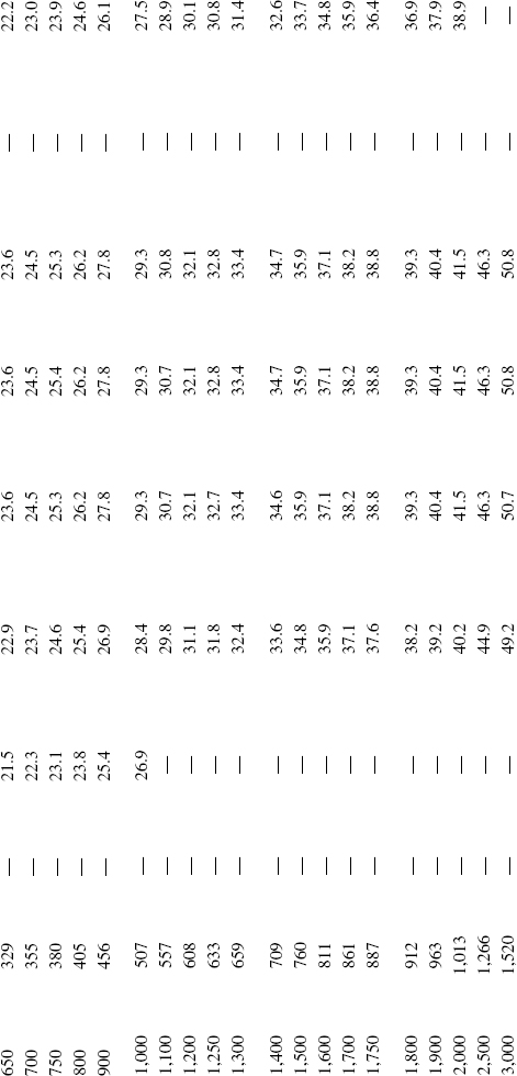
Tables 3.2 and 3.3 provide nominal DC resistance and nominal diameter values for solid and concentric-lay-stranded copper and aluminum conductors.
TABLE 3.2A
Nominal DC Resistance in Ohms per 1,000 Feet at 25°C of Solid and Concentric-Lay-Stranded Conductor
Source: |
ANSI/ICEA S-94-649, “Standard for Concentric Neutral Cables Rated 5,000–46,000 Volts,” 2004. |
* Concentric-lay-stranded includes compressed and compact conductors.
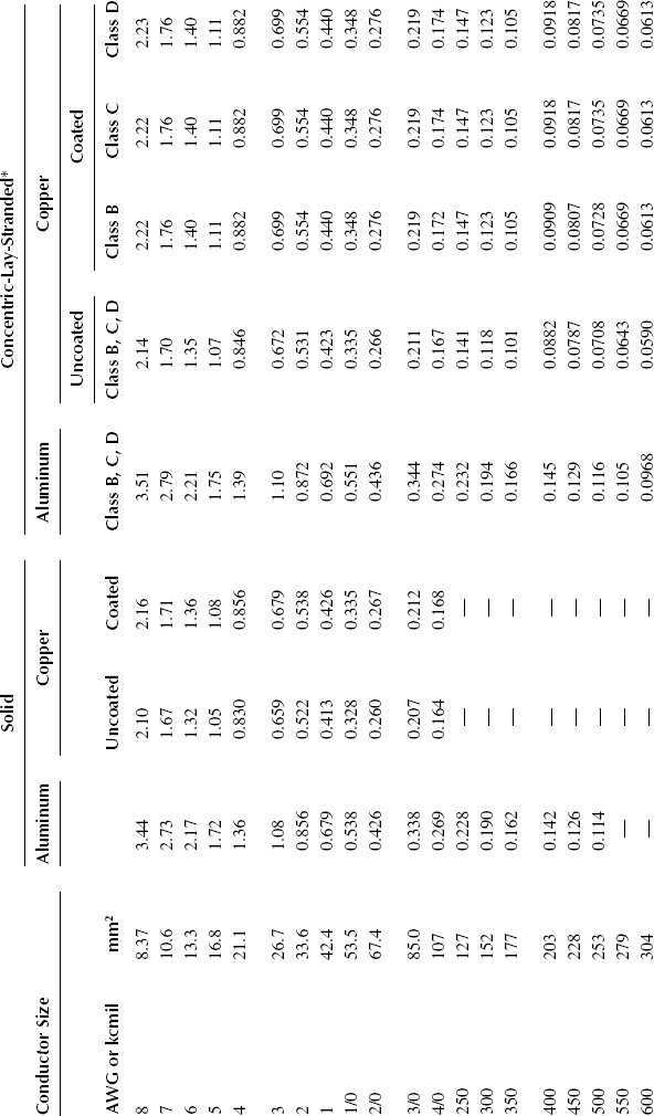
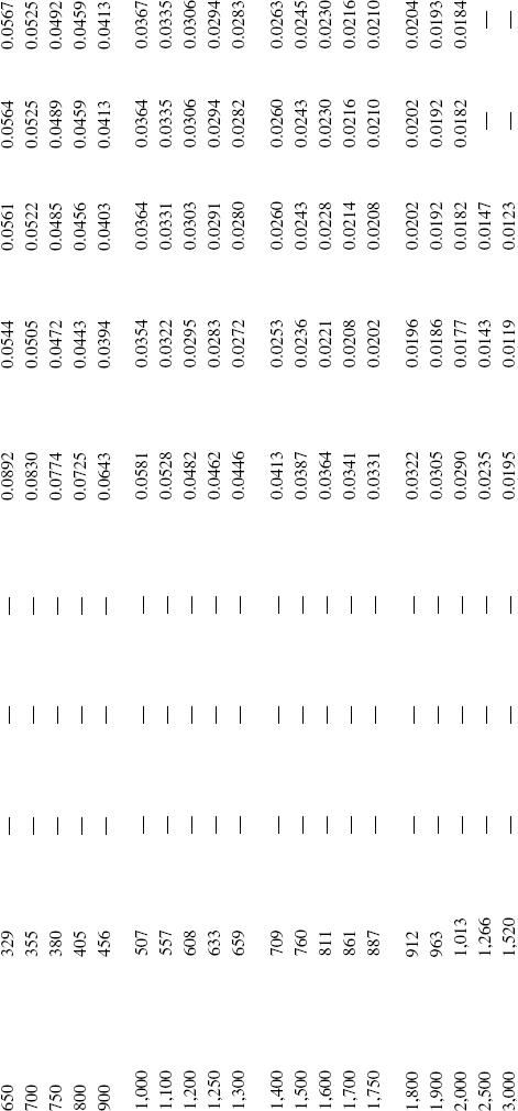
TABLE 3.2B (METRIC)
Nominal DC Resistance in Milliohms per Meter at 25°C of Solid and Concentric-Lay-Stranded Conductor
Source: |
ANSI/ICEA S-94-649, “Standard for Concentric Neutral Cables Rated 5,000–46,000 Volts,” 2004. |
* Concentric-lay-stranded includes compressed and compact conductors.
TABLE 3.3A
Nominal Diameters for Copper and Aluminum Conductors
Source: |
ANSI/ICEA S-94-649, “Standard for Concentric Neutral Cables Rated 5,000–46,000 Volts,” 2004. |
* Diameters shown are for compact round, compact modified concentric, and compact single input wire.
** Diameters shown are for concentric round and modified concentric.
TABLE 3.3B (METRIC)
Nominal Diameters for Copper and Aluminum Conductors
Source: |
ANSI/ICEA S-94-649, “Standard for Concentric Neutral Cables Rated 5,000–46,000 Volts,” 2004. |
* Diameters shown are for compact round, compact modified concentric, and compact single input wire.
** Diameters shown are for concentric round and modified concentric.
Except as noted above, most of the world uses the SI unit of square millimeters (mm2) to designate conductor size. The International Electrotechnical Commission has adopted IEC 60228 [8] to define these sizes. An important consideration is that these are not precise sizes. For instance, their 50 mm2 conductor is actually 47 mm2. To accommodate everyone, the IEC standard allows as much as a 20% variation in conductor area from the size designated.
In Canada, metric designations are used for all cable dimensions except for the conductor size. The variations in the two systems are too great to use any of the SI sizes as a direct substitute for standard sizes.
Conductors described in IEC 60228 are specified in metric sizes. North America and certain other regions at present use conductor sizes and characteristics according to the AWG system, and thousands of circular mils for larger sizes. The use of these sizes is currently prescribed across North America and elsewhere for installations by subnational regulations. IEC TC 20 cable product standards do not prescribe cables with AWG/kcmil conductors.
IEC TC 20 recognizes the need to produce a single, harmonized standard for conductors that is truly international. Harmonization, in this respect, is understood as the merging of AWG-based and metric-based sizes to produce one rationalized range of conductor sizes for power cables. TC 20 also recognizes that the development of such a harmonized standard is a long-term project.
A three-stage approach, which will culminate in a single International Standard for conductors, has been agreed.
Stage one of the approach is to produce a technical report that defines the range of AWG/kcmil sizes that are to be considered in the harmonization process.
Stage two of the process is to develop this technical report by starting the rationalization process. The test methods and requirements in this technical report are to be aligned with those in IEC 60228.
The third and final stage will be to produce a harmonized standard, based on IEC 60228 and the work of the first two stages, with a single, rationalized range of conductor sizes. The present expectation is that the third stage will not be achieved before 2020.
IEC Technical Report 62602 provides resistance and dimensional details for AWG and thousands of circular mils sizes as well as approximate equivalent metric nominal cross-sectional areas [9].
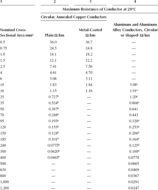
Table 3.4 provides maximum resistance values for solid Class 1 circular, annealed copper and circular or shaped aluminum and aluminum alloy conductors for use in single-core and multicore cables. Such conductors are available in nominal crosssectional areas up to 1,200 mm2.
Likewise, Table 3.5 provides maximum resistance values for stranded Class 2 circular, circular compacted and shaped annealed copper and aluminum and aluminum alloy conductors for use in single-core and multicore cables.
It should be noted that maximum or minimum diameter requirements are not specified in IEC 60228. Instead, it gives guidance on dimensional limits for the following types of conductors, which are included in this standard:
TABLE 3.4
Class 1 Solid Conductors for Single-Core and Multicore Cables
Source: |
IEC 60228 (Edition 3.0 2004-11), “Conductors of insulated cables,” Copyright © 2004 IEC Geneva, Switzerland. www.iec.ch |
a |
Aluminum conductors 10 mm2 to 35 mm2 circular only; see 5.1.1c. |
b |
See note to 5.1.1b. |
c |
See note to 5.1.2. |
d |
For single-core cables, four sectoral shaped conductors may be assembled into a single circular shaped conductor. The maximum resistance of the assembled conductor shall be 25% of that of the individual component conductors. |
TABLE 3.5
Class 2 Stranded Conductors for Single-Core and Multicore Cables
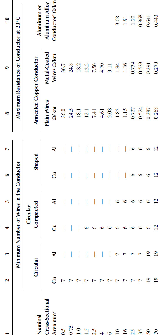
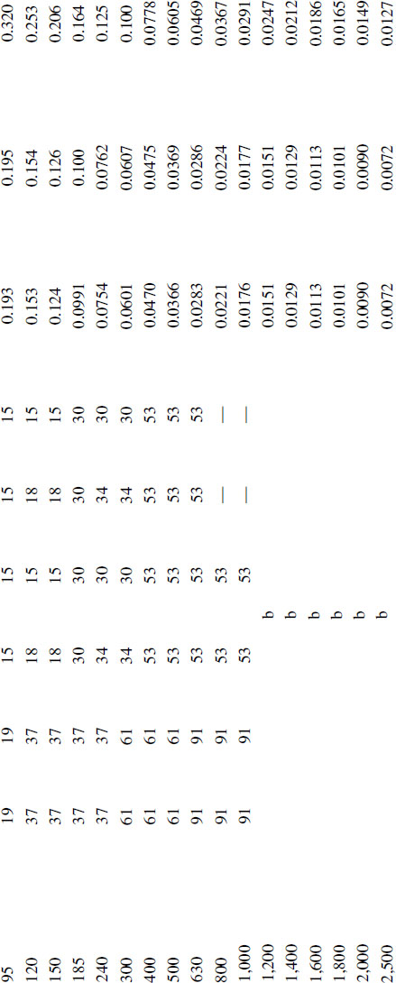
Source: |
IEC 60228 (Edition 3.0 2004-11), “Conductors of insulated cables,” Copyright © 2004 IEC Geneva, Switzerland. www.iec.ch |
a |
These sizes are nonpreferred. Other nonpreferred sizes are recognized for some specialized applications but are not within the scope of this standard. |
b |
The minimum number of wires for these sizes is not specified. These sizes may be constructed from 4, 5, or 6 equal segments (Milliken). |
c |
For stranded aluminum alloy conductors having the same nominal cross-sectional area as an aluminum conductor, the resistance value should be agreed between the manufacturer and the purchaser. |
1. circular solid conductors (Class 1) of copper, aluminum, and aluminum alloy;
2. circular and compacted circular stranded conductors (Class 2) of copper, aluminum, and aluminum alloy.
This is intended as a guide to the manufacturers of cables and cable connectors to assist in ensuring that the conductors and connectors are dimensionally compatible.
Larger sizes of solid conductors become too rigid to install, form, and terminate. Stranding becomes the solution to these difficulties. The point at which stranding should be used is dependent on the type of metal as well as the temper of that metal. Copper conductors are frequently stranded at #6 AWG and greater. Aluminum, in the half-hard temper, can be readily used as a solid conductor up to a #2/0 AWG size.
This is the typical choice for power cable conductors. This consists of a central wire or core surrounded by one or more layers of helically applied wires. Each additional layer has six more wires than the preceding layer. Except in unilay-stranded conductors, each layer is applied in a direction opposite to that of the layer underneath. In the case of power cable conductors, the core is a single wire and all of the strands have the same diameter. As shown in Figure 3.1, the first layer over the core contains 6 wires; the second, 12; the third, 18; etc. The distance that it takes for one strand of the conductor to make one complete revolution of the layer is called the length of lay. The requirement for the length of lay is set forth in ASTM standards [6] to be neither less than 8 nor more than 16 times the overall diameter (OD) of that layer.
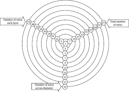
FIGURE 3.1 Concentric standing relationships.
TABLE 3.6
Examples of Class B, C, and D stranding
Size |
Class B |
Class C |
Class D |
#2 AWG |
7 × 0.0974 |
19 × 0.0591 |
37 × 0.0424 |
#4/0 AWG |
19 × 0.1055 |
37 × 0.0756 |
61 × 0.0589 |
500 kcmil |
37 × 0.1162 |
61 × 0.0905 |
91 × 0.0741 |
750 kcmil |
61 × 0.1109 |
91 × 0.0908 |
127 × 0.0768 |
In power cables, the standard stranding is Class B. Standards require that the outermost layer be of a left hand lay. This means that as you look along the axis of the conductor, the outermost layer of strands roll toward the left as they recede from the observer. More flexibility is achieved by increasing the number of wires in the conductor. Class C has one more layer than Class B; Class D has one more layer than C. The class designation goes up to M (normally used for welding cables, etc.). These are covered by ASTM standards.
Class C and D conductors have approximately the same weight as a Class B and an OD within 3 mils of Class B. Examples of Class B (standard), Class C (flexible), and Class D (extra flexible) are shown in Table 3.6 with the number of strands and diameter of each strand.
The following formula may be used to calculate the number of wires in a concentric stranded conductor:
(3.3) |
where n = total number of wires in stranded conductor and N = number of layers around the center wire.
This is the term that is used to describe a slight deformation of the layers to allow the layer being applied to close tightly. There is no reduction in conductor area. The diameter of the finished conductor can be reduced no more than 3% of the equivalent concentric strand. A typical reduction is about 2.5%. Examples of gaps in the outer layer for concentric stranded conductors are shown in Table 3.7.
TABLE 3.7
Gaps in Outer Layer of a Stranded Conductor
Total Number of Strands |
Angle of Gap at 16 × OD |
19 |
8.30 |
37 |
100 |
61 |
100 |
Shortening the length of lay on the outer layer could solve the problem but would result in higher resistance and would require more conductor material.
Compressed stranding is often the preferred construction, because concentric stranding, with its designated lay length, creates a slight gap between the outer strands of such a conductor. Lower viscosity materials that are extruded over such a conductor tend to “fall in” to any gap that forms. This results in surface irregularities that create increased voltage stresses and make it more difficult to strip off that layer.
This is similar to compressed stranding except that additional forming is given to the conductor so that the reduction in diameter is typically 9% less than the concentric stranded conductor. This results in a diameter nearing that of a solid conductor. Some air spaces that can serve as channels for moisture migration are still present. The main advantage of compact conductors is the reduced conductor diameter.
This term is applied to a collection of strands twisted together in the same direction without regard to the geometric arrangement. This construction is used when extreme flexibility is required for small AWG sizes, such as portable cables. Examples of bunch-stranded conductors are cords for vacuum cleaners, extension cords for lawn mowers, etc. Examples of bunch stranding are shown in Table 3.8.
Note that in Class K and M conductors, the individual wire diameters are constant and the cross-sectional area is developed by adding a sufficient number of wires to provide the total conductor area required.
This term is applied to a concentric-stranded conductor, each of whose component strands is stranded. This is a combination of the concentric conductor and a bunch-stranded conductor. The finished conductor is made up of a number of groups of bunch- or concentric-stranded conductors assembled concentrically together. The individual groups are made up of a number of wires rather than a single, individual strand. A rope-stranded conductor is described by giving the number of groups laid together to form the rope and the number of wires in each group.
TABLE 3.8
Examples of Class K and M Stranding
Conductor Size |
Class K |
Class M |
#16 AWG |
26 × 0.0100 |
65 × 0.0063 |
#14 AWG |
41 × 0.0100 |
104 × 0.0063 |
#12 AWG |
65 × 0.0100 |
168 × 0.0063 |
Note in Class K and M that the individual wire diameters are constant and the area is developed by adding a sufficient number of wires to provide the total conductor area required.
Classes G and H are generally used on portable cables for mining applications. Classes I, L, and M utilize bunch-stranded members assembled into a concentric arrangement. The individual wire size is the same with more wires added as necessary to provide the area. Class I uses #24 AWG (0.020 inch) individual wires, Class L uses #30 AWG (0.010 inch) individual wires, and Class M uses #34 AWG (0.0063 inch) individual wires. Class I stranding is generally used for railroad applications and Classes L and M are used for extreme portability such as welding cable and portable cords.
These have a cross section approximating the shape of a sector of a circle. A typical three-conductor cable has three 120° segments that combine to form the basic circle of the finished cable. Such cables have a smaller OD than the corresponding cable with concentric round conductors, and exhibit lower AC resistance due to a reduction of the proximity effect.
For paper-insulated cables, the sector conductor was almost always stranded and then compacted in order to achieve the highest possible ratio of conductor area to cable area. The precise shape and dimensions varied somewhat between the manufacturers.
Figure 3.2 and Table 3.9 show the nominal dimensions of typical compact sector conductors.
For the calculation of cable capacitance, for instance, an “equivalent round conductor” is required. Over the 2/0 AWG to 750 kcmil size range, the following formula holds:
(3.4) |
where D = equivalent round diameter in mils and A = area of sector conductor in circular mils.
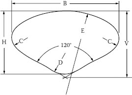
FIGURE 3.2 Outline of typical compact sector.
TABLE 3.9
Nominal Dimensions of 3/c Compact Sector Conductor
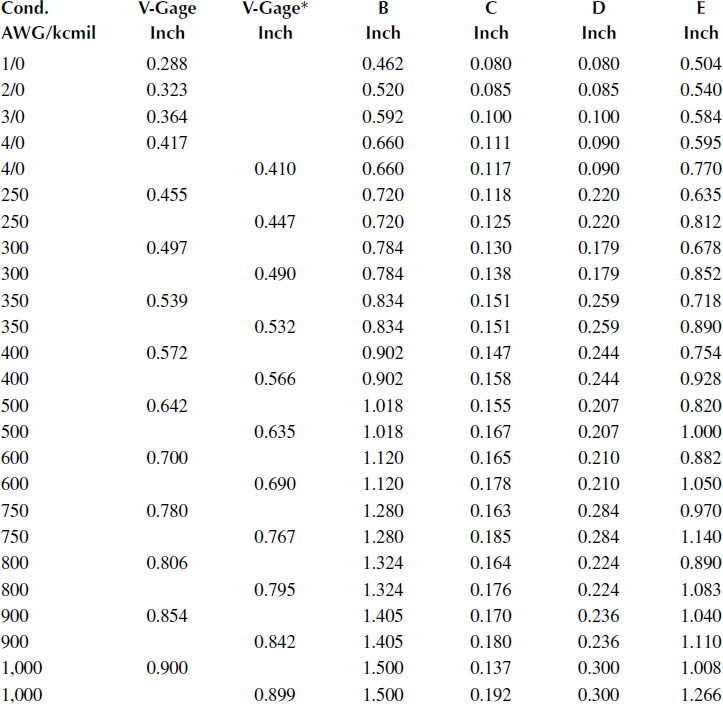
* Denotes the column that applies for insulation thickness over 200 mils.
Sector conductors that are solid rather than stranded have been used for low-voltage cables on a limited basis. There is interest in utilizing this type of conductor for medium-voltage cables, but they are not available on a commercial basis at this time.
These are round, stranded conductors composed of three or more segments that are electrically separated from each other by a thin layer of insulation around every other segment. Each segment carries less current than the total conductor, and the current is transposed between inner and outer positions in the completed conductor. This construction has the advantage of lowering the skin effect ratio and hence the AC resistance by having less skin effect than a conventionally stranded conductor. This type of conductor should be considered for large sizes such as 1,000 kcmil and above that are to carry large amounts of current.
The diameters of four-segment conductors are approximately the same as that of Class B concentric-stranded conductors (Table 3.10).
These are round, stranded conductors whose strands are laid around a core of rope, fibrous material, helical metal tube, or a twisted I-beam. This construction has the advantage of lowering the total AC resistance for a given cross-sectional area of conductor by eliminating the greater skin effect at the center of the completed conductor. Where space is available, annular conductors may be economical to use for 1,000 kcmil cables and above at 60 hertz and for 1,500 kcmil cables and above for lower frequencies such as 25 hertz.
TABLE 3.10
Nominal Diameters for Segmental Copper and Aluminum Conductors
Conductor Size |
Segmental Conductor Diameter* (Four segments) |
|||
kcmil |
mm2 |
Inches |
mm |
|
1,000 |
507 |
1.140–1.152 |
29.0–29.3 |
|
1,100 |
557 |
1.195–1.209 |
30.4–30.7 |
|
1,200 |
608 |
1.235–1.263 |
31.4–32.1 |
|
1,250 |
633 |
1.260–1.289 |
32.0–32.7 |
|
1,300 |
659 |
1.285–1.315 |
32.6–33.4 |
|
1,400 |
709 |
1.325–1.364 |
33.7–34.6 |
|
1,500 |
760 |
1.375–1.412 |
34.9–35.9 |
|
1,600 |
811 |
1.420–1.459 |
36.1–37.1 |
|
1,700 |
861 |
1.460–1.504 |
37.1–38.2 |
|
1,750 |
887 |
1.480–1.526 |
37.6–38.8 |
|
1,800 |
912 |
1.500–1.548 |
38.1–39.3 |
|
1,900 |
963 |
1.530–1.590 |
38.9–40.4 |
|
2,000 |
1,013 |
1.570–1.632 |
39.9–41.5 |
|
2,250 |
1,140 |
1.665–1.730 |
42.3–43.9 |
|
2,500 |
1,266 |
1.740–1.824 |
44.2–46.3 |
|
2,750 |
1,393 |
1.830–1.913 |
46.5–48.6 |
|
3,000 |
1,520 |
1.910–1.998 |
48.5–50.7 |
|
3,250 |
1,647 |
1.985–2.080 |
50.4–52.8 |
|
3,500 |
1,773 |
2.085–2.159 |
53.0–54.8 |
|
3,750 |
1,900 |
2.150–2.234 |
54.6–56.7 |
|
4,000 |
2,027 |
2.225–2.309 |
56.5–58.6 |
|
4,250 |
2,154 |
2.245–2.378 |
57.0–60.4 |
|
4,500 |
2,280 |
2.315–2.448 |
58.8–62.2 |
|
4,750 |
2,407 |
2.375–2.516 |
60.3–63.9 |
|
5,000 |
2,534 |
2.435–2.581 |
61.8–65.6 |
|
Source: |
ANSI/ICEA S-108-720, “Standard for Extruded Insulation Power Cables Rated Above 46 Through 345 kV,” 2004. |
* Diameter over binder tape.
Unilay has, as the name implies, all of its strands applied in the same direction of lay. A design frequently used for low-voltage power cables is the combination unilay where the outer layer of strands are partially comprised of strands having a smaller diameter than the other strands. This makes it possible to attain the same diameter as a compact stranded conductor. The most common unilay conductor is a compact, 8,000 series aluminum alloy.
3.7 PHYSICAL AND MECHANICAL PROPERTIES
Although high conductivity is one of the important features of a good conductor material, other factors must be taken into account. Silver is an interesting possibility for a cable conductor. Its high cost is certainly one of the reasons to look for other candidates. Silver has another disadvantage, which is its lack of physical strength that is necessary for pulling the cables into conduits.
Impurities have a very deleterious effect on the conductivity of copper. The specified purity of copper for conductors is 100%. Small amounts of impurities, such as phosphorous or arsenic, can reduce the conductivity to as low as 80%.
Electrical conductor (EC) grade aluminum is also low in impurities, 99.5% purity or better. ASTM B 233 specifies the permissible impurity levels for aluminum [6].
TABLE 3.11
Comparative Properties, Copper versus Aluminum
Property |
Unit |
Copper, Annealed |
Alum, Hard Drawn |
Density at 20°C |
Pounds/in3 |
0.32117 |
0.0975 |
Grams/cm3 |
8.890 |
2.705 |
|
Linear Temp. Coef. |
per °F |
9.4 × 10⁻⁶ |
12.8 × 10⁻⁶ |
of Expansion |
per °F |
17.0 × 10⁻⁶ |
23.0 × 10⁻⁶ |
Melting Point |
°F |
1981 |
1205–1215 |
Melting Point |
°C |
1083 |
652–657 |
3.7.1.3 Comparative properties, Copper versus Aluminum
Table 3.11 compares the properties of annealed copper and hard-drawn aluminum, which are typically used for power cable conductors.
Drawing of the copper and aluminum rod into wire results in work hardening of both. This results in a slightly lower conductivity as well as a higher temper. Stranding and compacting also increase the temper of the conductor. If a more flexible conductor is required, annealing the metal may be desirable. This can be done either while the strand is being drawn or the finished conductor may be annealed by placing a reel of the finished conductor in an oven usually having a nitrogen atmosphere and at an elevated temperature for a specified period of time.
ASTM Standards B1, B2, and B3 cover three tempers for copper conductors: hard-drawn, medium-hard-drawn, and soft or annealed, respectively. Soft-drawn is usually specified for insulated conductors because of its flexibility and ease of handling in the field. Medium-hard-drawn and hard-drawn are usually specified for overhead conductors.
ASTM Standards B231 and B400 cover concentric-lay and compact-round stranded aluminum conductors, respectively. ASTM has five designations for aluminum tempers as shown in Table 3.12. Note that some of the values overlap. Half-hard aluminum is usually specified for solid and for 8,000 series alloy conductors because of the need for greater flexibility. Three-quarter and full-hard are usually specified for stranded cables.
It is important to consider two factors before deciding which temper should be specified:
• The increased cost of the energy and equipment required to anneal the conductor.
• Even with a more flexible conductor, the overall stiffness of the insulated cable may only be marginally improved.
1350 Aluminum Tempers |
PSI × 103 |
Full Soft (H–0) |
8.5–14.0 |
1/4 Hard (H–12 or −22) |
12.0–17.0 |
1/2 Hard (H–14 or −24) |
15.0–20.0 |
3/4 Hard (H–16 or −26) |
17.0–22.0 |
Full Hard (H–19) |
22.5–29.0 |
Overhead conductors and cables that will be pulled in to long lengths frequently utilize higher tempers in order to increase the tensile strength of the conductor. Examples of cables that might require high tensile strength conductors are bore hole cables, mineshaft cables, or extremely long pulls of large conductors.
Moisture in an insulated conductor has been shown to cause several problems. Aluminum, in the presence of water and in the absence of oxygen, will hydrolyze. Thus, if water enters an insulated cable having an aluminum conductor, the aluminum and water combine chemically to form aluminum hydroxide and hydrogen gas. This condition is aggravated by a deficiency in oxygen in the insulated conductor. The chemical reaction is:
Aluminum hydroxide is a white, powdery material which is a good insulator. Many users of stranded aluminum conductors now require blocked conductors for this reason. Water blocking components, such as water-swellable tapes and yarns or sealants, incorporated into the interstices of the stranded conductor act as an impediment to longitudinal water penetration and thus help retard this form of deterioration. Copper conductors may, of course, also be water-blocked in the same manner.
Regardless of the conductor material and degree of compaction, there is still some air space remaining in the interstices of the stranded conductor. This space can act as a reservoir for moisture to collect and hence provide a source of water for water treeing. Water-blocked stranded conductors are frequently specified for underground cables to reduce the possibility of this happening. Solid conductors, of course, are typically specified for the same reason for #2/0 AWG and smaller aluminum conductors.
(3.5) |
where RDC = DC resistance of conductor in ohms per 1,000 feet at 25°C; ρ = resistivity of metal in ohm circular mils per foot; ρ for copper = 10.575 Ω·cmil/ft (100% conductivity) at 25°C; ρ for aluminum = 17.345 Ω·cmil/ft (61.0% conductivity) at 25°C; A = conductor area in circular mils.
The resistance of a stranded conductor is more difficult to calculate. It is generally assumed that the current is evenly divided among the strands and does not transfer from one strand to the next. For this reason, the DC resistance is based on:
• Multiply the number of strands by the cross-sectional area of each taken perpendicular to the axis of that strand. The product is then the cross-sectional area of the conductor.
• Compare the length of each strand to the axial length of the conductor. This increased length is arithmetically averaged.
• The DC resistance of a solid conductor having the same effective cross-sectional area is multiplied by the average increase in length of the strand. The resultant is the calculated resistance of the stranded conductor.
Since resistance is based on temperature, the following formulae correct for other temperatures in the range most commonly encountered:
Copper:
(3.6) |
Aluminum:
(3.7) |
where R2 = conductor resistance at temperature T2 in °C; R1 = conductor resistance at temperature T1 in °C.
These formulas are based on the resistance coefficient of copper having 100% conductivity and of aluminum having 61.2% conductivity (International Annealed Copper Standard).
A conductor offers a greater resistance to the flow of AC than it does to DC. This increased resistance is generally expressed as the AC/DC resistance ratio. The two major factors for this increase are the skin effect and the proximity effect of closely spaced current carrying conductors. Other magnetic effects can also cause an additional increase in AC/DC resistance ratios.
(3.8) |
The AC/DC resistance ratio is increased by larger conductor sizes and higher AC frequencies.
In AC circuits, the current tends to distribute itself within a conductor so that the current density near the surface of the conductor is greater than that at its core. This phenomenon is known as skin effect. A longitudinal element of the conductor near the center of the axis is surrounded by more lines of magnetic force than near the rim. This results in an increase in inductance toward the center. The decreased area of conductance causes an apparent increase in resistance. At 60 hertz, the phenomenon is negligible in copper conductor sizes of #2 AWG and smaller and aluminum sizes of #1/0 AWG and smaller. As the conductor size increases, this effect becomes more significant.
The following formula can be used to give an approximation of skin effect for round conductors at 60 hertz; another approximation will be given in Chapter 14.
(3.9) |
where YCS = skin effect expressed as a number to be added to the DC resistance; RDC = DC resistance of the conductor in micro-ohms per foot at operating temperature.
In closely spaced AC conductors, there is a tendency for the current to shift to the portion of the conductor that is away from the other conductors of that cable. This phenomenon is known as proximity effect. The alternating magnetic field linking the current in one isolated conductor is distorted by the current in an adjacent conductor. This in turn causes an uneven distribution of the current across the conductor cross section.
Since skin and proximity effects are cumbersome to calculate, tables have been established to give these values for common modes of operation [5].
3.9.5 CABLES IN MAGNETIC METALLIC CONDUIT
Due to excessive hysteresis and eddy current losses, individual phases of an AC circuit should not be installed in separate magnetic metal conduits under any circumstances. This is because of the high inductance of such an installation. In fact, separate phases should not pass through magnetic structures since overheating can occur in such a situation. All phases should pass through any magnetic enclosure simultaneously, so that maximum cancellation of the resultant magnetic field occurs. This greatly reduces the magnetic effect. However, even under these conditions, an increase in skin and proximity effects will occur because of the proximity of the magnetic material. There can be significant losses when large conductors are simply placed near the magnetic materials.
Cables in 50 or 60 hertz AC circuits should not be installed with each phase in a separate nonmagnetic metal conduit when their conductor size is #4/0 AWG or larger due to high circulating currents in the conduit. This causes a significant decrease in the cable ampacity.
3.9.6 RESISTANCE AT HIGHER FREQUENCIES
Cables operating at frequencies higher than 60 hertz may need to be evaluated for ampacity and AC/DC ratios because they can cause higher voltage drops than might be anticipated. Also at higher frequencies, an increase in the inductive reactance may affect voltage drops. Insulated conductors should not be installed in metallic conduits, nor should they be run close to magnetic materials.
For frequencies other than 60 hertz, a correction factor is provided by:
(3.10) |
where f = frequency in hertz, RDC = conductor DC resistance at operating temperature, in ohms per 1,000 feet.
For additional information on the effects of higher frequency, see the ICEA report in Reference [3] and the cable manufacturer’s manuals [4,5].
1. Kelly, L. J., 1995, adapted from class notes for “Power Cable Engineering Clinic,” University of Wisconsin–Madison.
2. Landinger, C. C., 2001, adapted from class notes for “Understanding Power Cable Characteristics and Applications,” University of Wisconsin–Madison.
3. ICEA P-34-359, 1973, “AC/DC Resistance Ratios at 60 Hz,” Global Engineering Documents, 15 Inverness Way East, Englewood, CO 80112.
4. “Engineering Data for Copper and Aluminum Conductor Electrical Cables,” 1990, The Okonite Company, Bulletin EHB-90.
5. Southwire Company Power Cable Manual, Second Edition, 1997, Carrollton, GA.
6. Annual Book of ASTM Standards, Vol. 02.03: Electrical Conductors. Section 2: Nonferrous Metal Products, 2010, ASTM International, 100 Barr Harbor Drive, PO Box C700, West Conshohocken, PA, 19428-2959 USA.
7. IEC 20/680/RVC Result of voting on 20/633/CDV: IEC 60228 Ed. 3: “Conductors of Insulated Cables,” 2004, IEC Central Office, 3 rue de Varembé, P.O. Box 131, CH-1211 Geneva 20, Switzerland.
8. IEC 60228 (Edition 3.0 2004-11), “Conductors of Insulated Cables,” 2004, IEC Central Office, 3 rue de Varembé, P.O. Box 131, CH-1211 Geneva 20, Switzerland.
9. IEC/TR 62602 (Edition 1.0 2009-09), “Conductors of Insulated Cables – Data for AWG and kcmil Sizes,” 2009, IEC Central Office, 3 rue de Varembé, P.O. Box 131, CH-1211 Geneva 20, Switzerland.
10. ANSI/ICEA S-94-649, “Standard for Concentric Neutral Cables Rated 5,000-46,000 Volts,” 2004, Global Engineering Documents, 15 Inverness Way East, Englewood, CO 80112.
11. ANSI/ICEA S-108-720, “Standard for Extruded Insulation Power Cables Rated Above 46 Through 345 kV,” 2004, Global Engineering Documents, 15 Inverness Way East, Englewood, CO 80112.