
CONTENTS
5.2 Physicochemical Properties of Materials Used as Electrical Insulation
5.2.2 Polyethylene Chain Length and Molecular Weight
5.3 Manufacture of Polyethylene
5.3.1 Conventional Manufacturing Methods
5.3.2 Controlled Molecular Weight Distribution Technology
5.4.2 Peroxide-induced Cross-linking
5.4.3 Radiation-induced Cross-linking
5.4.4 Silane-induced Cross-linking
5.4.5 Temperature Influence on Properties
5.5 Tree-Retardant Cross-linked Polyethylene
5.6 Ethylene Copolymer Insulations (EPR)
5.6.2 Additional EPR Considerations
5.6.3 All Ethylene–Propylene Rubbers Are Not Alike
5.6.4 Discharge Free versus Discharge Resistant
5.7.1 Overview and Role of the Polymer
5.7.3 Nonconducting Shield Materials
5.10.2.3 Paper–Fluid Combination
5.11 Low Voltage Polymeric Insulation Materials
5.12 Extruded Cable Rejuvenation
5.12.1 Introduction to the Concept
5.12.3 In-Service Procedure for Cable Rejuvenation
5.13 Comparison of Medium Voltage Insulating Materials
Appendix A: Polyethylene Chain Motion at Very Low Temperatures
Appendix B: Single Site Catalyst Polymerization
Electrical insulation materials are utilized to provide protection over the metallic conductors of underground cables. The insulating materials physically enclose the conductor and provide a margin of safety. These materials are composed of either synthetic or natural polymers. The polymeric insulation material selected for use may vary with the voltage class of the cable. For medium voltage cable constructions, compatible polymeric shields are employed between the insulation and the conductor, and over the insulation to grade the voltage stress; these are composed of flexible polymers blended with conducting carbon black that imparts the semiconducting characteristics. Metallic neutrals or tapes are applied over this cable core, and polymeric jackets are applied on the outside of the cable core.
Sections 5.2 to 5.10 of this chapter review polymeric insulation materials employed primarily in distribution and transmission cables, with reference to low voltage cable materials as needed. Fundamental principles will be reviewed. Section 5.11 discusses polymeric materials for low voltage cables. Section 5.12 deals with the fundamentals of aged-cable rejuvenation by impregnation. Chapter 6 will focus separately on electrical properties of insulating polymers discussed in this chapter.
Until the early 1980s, transmission class cables (defined as cables operating above 46 kV) had traditionally employed oil-impregnated paper as the insulation. This paper insulation is applied as thin layers wound over the cable core, and is later impregnated with a dielectric fluid. Paper-insulated lead covered (PILC) cable was also used at distribution voltages. Paper-based insulated cables are still being installed today; however, as the application of synthetic polymers to cable technology matured, extruded polyethylene that has been subjected to cross-linking (XLPE) gradually displaced paper and can be considered as the insulation material of choice for transmission voltages. XLPE has traditionally been considered as preferred due to its ease of processing and handling (as well as cost), although paper/oil systems have a much longer history of usage and much more information on service reliability exists. Care in handling of materials and assurance of extreme cleanliness prior to and during manufacturing are required for all extruded cables.
For distribution voltage class cables (mostly 15 to 35 kV), the prime extruded material developed for use in the 1960s was conventional high molecular weight polyethylene (referred to as polyethylene, or HMWPE) [1]. However, this insulation material (also referred to as being a thermoplastic polymer, meaning it can be recycled) was replaced by XLPE (referred to as being a thermoset polymer, meaning it cannot be recycled) as the material of choice during the late 1970s–early 1980s, as a result of unanticipated early failures in service due to the water-treeing problem (see Chapter 19). Installed polyethylene-insulated cables are gradually being replaced (or rejuvenated in-situ for stranded constructions [see Section 5.12]). Elastomeric ethylene–propylene copolymers have also been used (EPR or EPDM) for low and medium voltage cable insulation and are employed for accessories. The term EP has been used to generically describe both EPR and EPDM-insulated cables and “EPR” is the terminology that will be applied here. EPR cables have been available since the 1960s, but their use had been consistently less common as compared with HMWPE or XLPE due to higher costs and operating losses. EPR usage started to increase from the 1970s to 1980s partly due to easier processing as a result of modification of the EPR compound to facilitate easier extrusion (hence reducing the cost). In contrast to XLPE, which is a semicrystalline polymer, EPR is an elastomer (rubber) and therefore requires the incorporation of inorganic mineral fillers (and other additives) in order to allow EPR to serve as a satisfactory functional insulation; the requirement to blend in additional additives leads to additional handling and processing requirements by materials suppliers [2].
Starting in the mid-1980s, XLPE had been gradually replaced by “tree retardant” XLPE (TR-XLPE) as the material of choice for new distribution class cables. From the early 1980s and well into the late 1990s, a single grade of TR-XLPE was employed commercially in North America. Several grades of TR-XLPE have been available over the years as improvements have been incorporated [3].
Although many of the older insulated cables manufactured with HMWPE, EPR, and XLPE insulations are still in service on many utility systems, the insulation choices for new medium voltage cables today are considered to be TR-XLPE and EPR. It should be noted here, however, that all EPRs are not alike. All these subjects will be discussed in greater detail later in this chapter.
The use of present-day XLPE, TR-XLPE, and EPR grew out of prior experience going as far back as World War II. As described in Chapter 1, development and application of the various early insulation materials employed for wire and cable were, progressively, natural rubber, synthetic rubber, and butyl rubber, each representing improvements. Butyl rubber was in common use when it was replaced by EPR for many applications. HMWPE was employed due to its superior electrical properties and ease of handling. Virtually all of the older butyl-based installed cables for distribution applications have now been replaced.
Polymers such as polyethylene, XLPE, polypropylene (PP) (used as jacket material), and ethylene–propylene copolymers and terpolymers are hydrocarbon polymers, and are known as polyolefins. Polyethylene and PP are known as homopolymers; EPR is known as a copolymer, meaning that it is composed of two different polymers in the chemical structure. It is manufactured by copolymerizing ethylene and propylene gases. These polymers are composed exclusively of carbon and hydrogen.
It is also possible to replace propylene with other monomers; examples are vinyl acetate (EVA) and ethyl acrylate (EEA). These copolymers of polyethylene are employed as shield materials (see Section 5.7). Copolymerization with other monomers referred to as alkenes has led to commercialization of materials known as EAM (ethylene alkene copolymers).
Preferred insulation characteristics of this class of polyolefin-based polymers include:
• Excellent electrical properties
• Low dielectric constant
• Low power factor
• High dielectric strength
• Excellent moisture resistance
• Extremely low moisture vapor transmission
• High resistance to chemicals and solvents
• Ease of processing and extrusion
Paper-insulated cables were historically one of the first types of polymer used since paper was, and is, readily available from natural sources. Paper is derived from wood pulp and is a natural polymer based on cellulose. In use, the paper is impregnated with a dielectric fluid (a low molecular weight hydrocarbon) so the practical insulation is actually a two-phase composition. PILC cables have been employed at distribution voltages since the early twentieth century; many of these cables are also still in service, even after 60 to 70 (or more) years. They are highly reliable (partly due to the presence of an outer lead sheath that provides protection from the local environment), which makes them a construction of choice for many urban locations. They may be preferred in specific locations where existing duct size and space are limited. Paper insulation is discussed in more detail in Section 5.10.
The dielectric losses of polyolefins are superior to those of paper/oil insulation systems, and the polymers are considerably more moisture-resistant than paper. A moisture-resistant sheath has always been incorporated into paper cable designs.
At lower operating voltages, the possible choice of polymeric materials widens. Here it is possible to use polyvinyl chloride (PVC), silicone rubber (SIR), or other polymers that are readily available and easily processed. PVC was used for a time in Europe for medium voltage cables in the 10 to 20 kV class, but that practice has been largely discontinued. PVC is actually a tough, rigid polymer, and requires a softening agent (plasticizer) to increase flexibility and render it useful for wire and cable applications.
At the lower voltages, such as those employed for secondary cable, reliability is related primarily to operating temperatures rather than operating voltage stress or losses, and thermal resistance becomes a priority. At low voltage levels, other properties can be addressed, such as ability to impart for example, flame resistance, and polymer insulations such as Neoprene and Hypalon are factors. This is discussed in Section 5.11.
Each insulation type has certain advantages and disadvantages. An overview of present-day medium voltage insulations is summarized as follows:
Insulation Type |
Key Property Information |
Polyethylene |
Low dielectric losses |
Moisture sensitive under voltage stress |
|
XLPE |
Slightly higher dielectric losses than polyethylene |
Less moisture sensitive than polyethylene; ages more slowly |
|
Excellent properties if kept dry |
|
EP (EPR/EPDM) |
Higher dielectric losses vs. XLPE or TR-XLPE |
More flexible, less moisture sensitive than XLPE or polyethylene |
|
Requires inorganic filler additives |
|
Many different compositions available; some proprietary |
|
TR-XLPE |
Losses slightly greater than XLPE |
Losses less than EPRs. |
|
Less moisture sensitive than XLPE; ages more slowly |
|
PILC |
High reliability |
Manufactured with a lead sheath |
In addition to use as primary insulation, polymers are employed as components of conductor and insulation shields. These materials are ethylene copolymers that possess controlled quantities of conducting carbon black (and often other ingredients) to provide the semiconducting properties required for shields. It is the use of the conducting material dispersed throughout the polymer matrix that makes the mixture semiconducting in nature; hence, the term “semiconducting” is applied to shield materials. The copolymer itself can be viewed as a “carrier,” but this carrier must possess the property of controlled adhesion to the insulation with which it is in contact.
Almost all present extruded cable constructions are covered by an outer extruded jacket. The purpose of the jacket is to reduce moisture ingress, protect the cable mechanically (e.g., during handling and installation and from abrasion), and also to provide resistance to sunlight and ultraviolet light. Jackets are commonly composed of one of several polyethylene types (low, medium, or high density) or PP, and also contain small quantities of carbon black, which provides the resistance to light. Jackets are of two types, insulating and semiconducting; insulating jackets contain a different type of carbon black compared with that used in semiconducting shields (it is nonconducting), and it is present in much smaller quantities. For semiconducting jackets, as might be expected, the carbon black used is similar to that used in shields. Polymeric jackets are discussed in Section 5.8. As noted earlier, the covering used for paper/oil cables is a lead sheath.
This chapter will review the following topics:
1. Properties of semicrystalline polymers such as polyethylene from a fundamental perspective. Basic topics such as molecular weight, molecular weight distribution, branching, crystallinity, and cross-linking are reviewed
2. Methodologies for inducing cross-linking of the polyolefins; function of peroxides and antioxidants
3. Introduction to manufacturing processes for polyolefins
4. XLPE and TR-XLPE, including thermal effects
5. Properties of EPR and how it differs from polyethylene, XLPE, and TR-XLPE
6. Review of extruded shield and jacket technology
7. Fundamentals of paper/fluid cables that employ cellulosic insulation along with low molecular weight hydrocarbon-based fluids, and how the cellulose differs from polyolefins
8. Fundamentals of low voltage cable insulation materials
9. Treatment of extruded cables in the field to extend life (rejuvenation)
The fundamental properties to be focused on here are important to understand since the properties that the electrical insulations possess and display are related to their physicochemical structure; the latter primarily controls the physical as well as the electrical properties. By understanding the fundamentals of their chemical nature as described herein, we will be defining the properties. In essence, we will be providing an overview of “structure-property relationships.”
5.2 PHYSICOCHEMICAL PROPERTIES OF MATERIALS USED AS ELECTRICAL INSULATION
Although use of polyethylene itself as insulation for new medium voltage cables has been essentially discontinued, the properties of this polymer will be reviewed first as a “model” as it is a homopolymer from which the other insulating materials are derived and continue to be used for low voltage insulation. When XLPE is considered, the starting material is polyethylene; when EPR, an ethylene copolymer, is considered, the starting material for discussion is the ethylene homopolymer, i.e., polyethylene. Hence, once the basics of polyethylene are described and understood, it will be easier to understand the properties of EPR, XLPE, and also TR-XLPE.
The chemical structure as it relates to molecular weight and chain branching will be reviewed, followed by the subjects of crystallinity and cross-linking of polyethylene. This in turn will lead to a discussion of the properties of XLPE. Some aspects of polyethylene manufacture will also be covered. With this as background, the discussion will be followed by the properties of copolymers of ethylene such as EPR, why fillers are required, and the differences between different EPRs. Finally, semiconducting shields and then jackets will be discussed.
5.2.2 POLYETHYLENE CHAIN LENGTH AND MOLECULAR WEIGHT
Polyethylene is a hydrocarbon polymer composed exclusively of carbon and hydrogen. It is manufactured from the monomer ethylene (in turn, derived from the cracking of petroleum), as shown in Figure 5.1. Note that the chemical structure is a series of repeating −CH2− units.
Hence, the individual molecules of ethylene gas combine to produce a polyethylene “chain.” During this process, the gas is converted to a solid. The number of ethylene molecules (often referred to as “mers”) in the chain is significant.
FIGURE 5.1 Ethylene polymerization to polyethylene.
Polyethylene falls into the class of polymers known as polyolefins (PP is another example). Key properties of interest relate to molecular weight, molecular weight distribution, branching, cross-linking, as well as crystallinity [4].
Polyethylene is produced by one of several processes that are summarized in Section 5.3. While details are beyond the scope of this book, it is necessary to note that the method of manufacture of the polyethylene controls whether it is “high density,” “medium density,” “low density,” or “linear low density,” terms commonly employed in the cable industry. Density is a measure of crystallinity (discussed later in this chapter), and is a factor that determines what makes the specific polyethylene type applicable as an insulation, semiconducting material, or jacket material. Hence, the method of polyethylene manufacture controls the exact chemical structure, which in turn controls the properties.
The carbon–hydrogen polymeric structure noted in Figure 5.1 is simplified; the chemical structure of polyethylene is actually more complex than is shown there (as might be deduced from the number of key subjects noted above). Figure 5.2 shows the carbon–hydrogen structure and for simplicity, we can depict that structure as a wavy line.
The wavy line is referred to as a “chain” and the length of the chain is significant. The length of the line is related to the molecular weight, and the “wave” indicates that the chain has a tendency to coil. The greater the number of ethylene molecules incorporated into the polyethylene chain, the higher the molecular weight (and the greater the degree of coiling). Hence, a longer chain of polyethylene has a higher molecular weight than a shorter chain, and the molecular weight increases as the number of ethylene groups in the molecule increases. Of interest is the fact that the polyethylene employed as insulation for medium voltage cables in the past was described and commonly referred to as “high molecular weight polyethylene” (or HMWPE). It was not referred to as low molecular weight polyethylene for a reason; the properties of HMWPE are far superior.
However, the actual molecular weight of polyethylene used as cable insulation (or for other applications) is more complex than as described so far. It cannot be accurately described as a single coiled chain. Conventional polyethylene is actually composed of numerous chains (not a single one as discussed so far), and the chain lengths of individual molecules can vary considerably. Hence, in reality, polyethylene is composed of polymer chains that have a distribution of molecular weights (chain lengths). Indeed, the molecular weight distribution is a means of characterizing the polyethylene. This merely means that the “average” chain length is what is referred to and is considered to be “high.” As can be inferred, the higher the molecular weight, the better the overall properties.
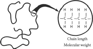
FIGURE 5.2 Depiction of polyethylene chemical structure.
Since typical polyethylenes that have been employed for electrical insulation contain a variety of individual chains of different lengths (i.e., weights), it is easy to see that there can be a large number of commercially available grades of polyethylene, all varying in “average” molecular weight.
The average molecular weight can be described in several ways. The terms employed most often are “weight average” (Mw) and “number average” (Mn) molecular weight. These values arise from different mathematical methods of averaging the molecular weights in polymer samples possessing molecules of different sizes. The mathematical definitions of the number and weight averages are related to the smaller and larger sized molecules, respectively. Hence, the average molecular weight is always greater than the number average. [When the polymer insulation is cross-linked, the molecular weight determination becomes more complex since the cross-linked fraction can be considered to have an “infinite” molecular weight.] From the perspective of the cable engineer, what is relevant to understand is that there is no single way of characterizing the polymer molecular weight.
The average molecular weight (and distribution) can be determined by a technique referred to as gel permeation chromatography. The molecules of different weights are separated, but the equipment required to perform this is complex, expensive, and special training is required. A simpler alternate method of characterization (to meet most purposes) is to measure the viscosity (resistance to flow) of the polymer; the higher the average molecular weight, the higher the viscosity. The equipment required to measure viscosity is significantly less complex than that required to measure the average molecular weight directly, so focusing on this function of the average molecular weight is common. One method involves determining flow of the polymer through an orifice at a temperature above the crystalline melting point range. Since flow is slower as the average molecular weight increases, due to the higher viscosity, this function of molecular weight is readily characterized. This is referred to as melt flow index. Another method involves use of a rotating disc to measure the viscosity, and this is more common with elastomers. Again, the higher average molecular weight provides better overall properties in application. It is also possible to gain an understanding of the molecular weight distribution by measuring the viscosity of the polymer after it is dissolved in a solvent [5].
Figure 5.3 provides a perspective on the molecular weight distribution of polyethylene [1] and demonstrates why it is so difficult to provide a “single” number. The average based on the weight (Mw) offers the highest value; in this case about 80,000; the average based on the number of molecules in the chain (Mn) in this case provides an estimate of about 8,000 (Mw is always greater than Mn). However, the figure shows that there are a small percentage of molecules having much lower (1,000) and much higher (almost 1 million) molecular weights. The Mw/Mn ratio is considered a satisfactory method of characterization.
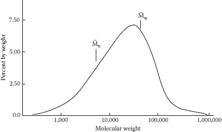
FIGURE 5.3 Typical molecular weight distribution of polyethylene.
EPR (which is discussed in detail in Section 5.2.4) is a copolymer of ethylene and propylene (which means that the two gases are blended together prior to polymerization). EPR, also referred to as a polyolefin, is an elastomer, and it is noted here that all the principles reviewed relating to molecular weight, molecular weight distribution, viscosity, and branching (see Section 5.2.3) also apply to EPR.
When ethylene monomer is converted to ethylene polymer (polyethylene), the polymer chains that form are not always linear as shown in Figure 5.2. There is a tendency to form side chains or “branches.” These branches are “hanging” off the main chains as appendages (like “T”s). This is a natural event; when polyethylene is manufactured, the process employed always leads to side chains “hanging” off the long main chain. The chain branching phenomenon contributes to increase in the molecular weight, but does not lead to an increase in the chain length. Branches for various grades of polyethylene are shown in Figure 5.4; note that the chain length of the branches can also vary, and that there are both long and short chain-length branches. It is possible to control the length and distribution of the branches (via the polymerization process).
The significance of branching is that their length and distribution affect the physical properties and also influence the ability to satisfactorily extrude the polyethylene.
It is possible to now visualize that two single molecules may have the same exact molecular weight, but one may have a longer main chain with few branches, and the other a shorter main chain with a longer branches than the first. Therefore, two different polyethylene material batches having many molecules like the two described here (if it were possible to manufacture these) could have different properties, despite having approximately the same molecular weight distributions.
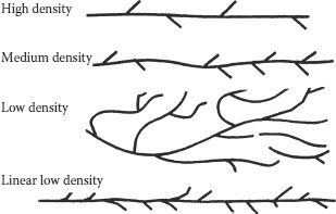
FIGURE 5.4 Structures of polyethylene depicting branches.
Branching also affects the ability of the polyethylene to crystallize (see Figure 5.4). However, branching does not have any meaningful influence on the electrical properties, such as dielectric strength or losses.
In Figure 5.2, we have depicted the polyethylene chain as a wavy (rather than straight) line, and that is because the chains have a tendency to coil. In other words, they have a tendency to achieve a random configuration (like a bowl of spaghetti). This coiled configuration is better shown in Figure 5.5. When depicting the branching in Figure 5.4, we did not focus on the aspect of coiling as the objective was to emphasize the branching. However, it is easy to visualize branches “hanging” from the coiled structure of Figure 5.5. This tendency is independent of the molecular weight, but the configuration that results is influenced by the branching.
The tendency to coil means that the polymer chains also have a tendency to entangle with each other. These entanglements mean that when the chains are pulled apart (as occurs in performing a tensile strength or elongation measurement), there will be some “resistance” to movement. Such chain entanglements influence the mechanical properties of the polymer. These entanglements contribute to the good properties of polyethylene, but not to the qualities that make polyethylene resistant to the penetration of water vapor. Entanglements do not have a major influence on electrical properties.
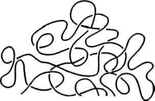
FIGURE 5.5 Simplified depiction of random coiled configuration.
In conclusion, molecular weight, molecular weight distribution, and branching represent several important characteristics of polyethylene that influence properties and also represent methods of describing the characteristics of polyethylene insulation.
Another very important characteristic of polyethylene is the subject of crystallinity. Polyethylene and some other polyolefins (PP being an example) are known as semicrystalline polymers. This characteristic results from the fact that the polymer chains not only have a tendency to coil (as previously described), but also have a tendency to align themselves relative to each other (Figure 5.6). Alignment means that there are short- and long-term orders to the chain structure. While the nature of these alignments is quite complex, and the detailed structure is beyond the scope of this chapter, it is important to understand that the alignment contributes to the crystalline nature of the polyethylene, and therefore to the density and ultimately to properties, such as stiffness and resistance to migration of impurities.
For polyethylene, different chain segments also have a tendency to align next to each other. The aligned portions cannot coil. The portions that are not aligned can coil. The chain portions that are aligned are said to be “crystalline.” The chain portions that are not aligned are described as “amorphous.”
The lower portion of Figure 5.6 shows chain alignment where the polymer chain lengths differ. Some portions of the same chains align with adjacent chains, and some portions of the very same chains are not aligned. Those chain portions where alignment occurs are in the regions called “crystalline.” Figure 5.6 shows that such alignment is not necessarily related to molecular weight. It is theoretically possible to have low or HMWPE of the same, or different, degrees of alignment.
The nature of the crystallinity in polyethylene has been the subject of numerous studies over the years. These studies reveal that the crystalline structure is more complex than that described so far. Crystallites, or crystalline regions of the polyethylene, can themselves fold (like a series of connected upright and upside-down “U”s),” Various possible descriptions are shown in Figure 5.7. Semicrystalline polymers are ‘tough’ at ambient but soften at elevated temperatures (crystalline regions melt and become amorphous)
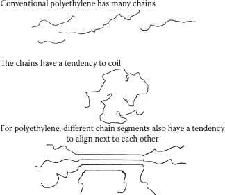
FIGURE 5.6 Polyethylene chain configurations.
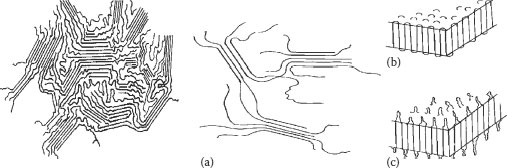
FIGURE 5.7 (a–c) Various depictions of semicrystalline polyethylene.
These regions can, in turn, align into larger structures called spherulites (which can be seen under polarizing light). The size of these spherulites may vary, as can the fold dimensions of the crystallites. The folded regions are referred to as lamellae. While all these structures “disappear” on melting (and re-form in a qualitatively similar manner upon subsequent cooling), it is known that upon annealing below the melting temperature range, changes in the lamellae thickness occurs. It is also known that there may be numerous crystallites in a spherulite; it is possible for one polymer chain within a crystallite to cross through the amorphous region into another crystallite, becoming what is called a “tie molecule.” The latter are considered to influence mechanical properties.
Regardless of the “fine” structure previously described (further details are beyond the scope of this chapter) from a practical perspective regarding cable insulation behavior, it is the crystalline regions that impart polyethylene with desirable properties such as toughness, high modulus, and moisture and gas permeation resistance. Those regions that are aligned possess increased density due to “tighter” chain packing, and the increased crystallinity resulting from chain alignment leads to higher density. The alignment process logically means less amorphous regions in the polymer and more polymer per unit volume. Nevertheless, the amorphous regions play a significant role in controlling properties such as increased ductility and flexibility and they also facilitate processing.
For simplification, polyethylene can be visualized as being a “blend” of two materials having different geometrical components, even though the chemical structure of the polymer is comprised solely of −CH2− groups. The “two materials” are the crystalline and amorphous regions.
As might be surmised, branching (as previously described) influences the ability of the polyethylene chains to align. Both long chain branches and short chain branches hinder the ability of the polyethylene main chain backbone components to crystallize (but not equally). Branching, therefore, due to the “bulky” nature of the chemical structure of the polymer chains, influences the crystallization process. For crystallinity to occur, nonbranched chain segments must be able to approach each other. When branching is present, the ability of the main chain to come in close proximity to another main chain is hindered.
Different polyethylenes have historically been classified into the following general categories due to this phenomenon (see Figure 5.4); the density increases from the 0.91 (g/cc) range for very low density polyethylene (VLDPE) to the 0.94 range for HDPE:
• Very low density
• Low density
• Medium density
• High density
• Linear low density
As the density increases, the degree of chain alignment increases and the “volume” of aligned chains increases. As noted above, the degree of branching is related to the polymerization process. Linear low density polyethylene (LLDPE) approaches the branching structure of high density polyethylene (HDPE), but is referred to differently due to the fact that it is manufactured by a different polymerization process. Branching clearly influences crystallinity, but the latter is minimally affected, if at all, by the conversion of polymer pellets into cable insulation during the extrusion process.
As noted previously, as the degree of crystallinity varies, the properties vary. Increased crystallinity leads to increased density. Hence, in principle, it is theoretically possible to have the following different types of polyethylenes:
• High density, high molecular weight
• High density, low molecular weight
• Low density, high molecular weight
• Low density, low molecular weight
Not all these types are of practical interest for cable (or other) applications. Low density, high molecular weight is, as we have seen, the type commercially provided and employed as cable insulation in the past. (This was known simply as HMWPE.) HDPE (of varying molecular weights) has been and continues to be employed as jackets. (As noted earlier, when referring to molecular weight, we are referring to averages.)
One further characteristic of polyethylene that influences crystallinity is worthy of mention at this point. This is the effect of temperature on the polymer chain alignment and motion at the molecular level as a function of temperature. As the temperature increases, the chains will move farther apart as they absorb heat. This motion disrupts the alignment and crystalline melting takes place (see Section 5.4.5).
Copolymers are insulation materials that are manufactured by incorporating more than one monomer during the polymerization process (see Section 5.3). Ethylene monomer is a gas; when ethylene is polymerized alone, solid polyethylene is produced. If gaseous propylene monomer is mixed with the ethylene prior to polymerization, one obtains ethylene–propylene copolymer(s)—hence EPR. What should be apparent is that the ratio of ethylene to propylene (E/P) employed in the polymerization process should influence the E/P ratio in the ultimate EPR insulation material. It should be possible to manufacture a wide variety of EPR copolymers each with different E/P ratios, and indeed this is so. However, not all E/P ratios in polymers make them suitable as insulation materials; an E/P ratio of 50%–70% may be typical for different insulations. This ratio also influences the method used to extrude the polymer as cable insulation.
Copolymerization, as described here, is different from mixing polyethylene and polypropylene after manufacture of the homopolymers. In the latter case, one does not have a copolymer, but a blend with entirely different properties. Indeed, polymer blends are often incompatible, and phase separation of the different polymers can occur; that does not happen with true copolymers.
It is also possible to manufacture copolymers of ethylene with monomers other than propylene. Common monomers for wire and cable applications include EVA or EEA. These latter copolymers (E-VA or E-EA) are employed in shield compounds. As with polyethylene or EPR, the chain lengths may vary, branching is common, and their chain lengths influence properties. The relative amounts of the second (copolymerized) monomer must also be taken into consideration when evaluating the properties. It is also possible to copolymerize ethylene with various other monomers, possible examples being butene or higher unsaturated hydrocarbon monomers (different monomers would provide different chain lengths on the branches).
When ethylene is copolymerized with other monomers, the result is polymer structure(s) that can disrupt the ability to impart crystallinity. We are now producing polymers that are more rubbery (elastomeric) rather than crystalline in nature. The properties are now drastically changed and this will be discussed in detail in Section 5.6. A question arises as to how to classify such rubbery copolymer materials and the numerous possible compositions based on them. This applies to all elastomers, even those that are not based on polyethylene copolymers. The approach is to apply designations described in ASTM D-1418, where rubbers of the polyethylene type (the ones of interest to us here) are designated “M” and the term EAM has been applied to some copolymers of polyethylene.
It is not uncommon to polymerize ethylene with more than one additional monomer, hence producing a terpolymer. This will be discussed with reference to EPR.
It can be noted that some older polymer systems used for wire and cable are copolymers. For example, butyl rubber (commonly employed prior to the advent of EPR) is composed of a copolymer of two monomers known as isobutylene and isoprene, the latter being present in the 1%–3% range. Even earlier, synthetic rubber (developed to replace natural rubber) is a copolymer of butadiene and styrene, the ratio being 75:25.
5.3 MANUFACTURE OF POLYETHYLENE
5.3.1 CONVENTIONAL MANUFACTURING METHODS
Historically, low and medium density polyethylenes (MDPEs) have been manufactured by a high-pressure polymerization process [4]. This process induces polymerization of ethylene gas in a reactor vessel under extreme conditions of very high pressure and temperature and leads to the branched polyethylene structures discussed above. It also employs a peroxide initiator to induce the polymerization. The polymer produced in the reactor is extruded through a die, pelletized and cooled after manufacture.
HDPE is manufactured through a low pressure process using a different catalyst concept. The low pressure process, developed later in time, uses nonperoxide catalysts, one of which is called “Ziegler-Natta” (named after the inventors) and allows manufacture of polyethylenes with fewer and shorter branches. This process produces a stiffer, tougher type of polyethylene, and is termed “high density.” LLDPE, developed even more recently, is manufactured by a low pressure process; as can be seen from Figure 5.4, it has many short chain branches, rendering it more like HDPE in structure. (That is why it is called “linear low density polyethylene,” rather than “high density polyethylene”).
The different types of polyethylenes are therefore all manufactured by different processes. Recall that all these processes will provide a polymer with a variety of (different) degrees of crystallinity (hence, density) and also a variety of molecular weight distributions.
The manufacturing technology is continuously improving, as discussed in the next section.
5.3.2 CONTROLLED MOLECULAR WEIGHT DISTRIBUTION TECHNOLOGY
Changes in catalyst polymerization technology have been the objective of ongoing studies. Results have allowed materials suppliers to better control the molecular weight and molecular weight distribution, and this led to development of newer grades of polyethylene having narrower and more defined molecular weight distributions (and various low density grades). Polymerization processes have been referred to as “single site catalysis,” and metallocene catalyst represented one methodology focused on in the past years [7].
This area of activity for improved control of polymer properties has received much attention. Fundamental properties such as molecular weight were described in Section 5.2. It was noted there that the polyethylene or EPR (polyethylene copolymer) used for cable manufacturing does not have a single uniform molecular weight (all the molecules do not have the same length) but possesses a distribution of molecular weights. This is because the catalyst technology used to manufacture conventional high-, medium- or low-density polyethylene cannot provide such an exact control of the polymerization process. This distribution of molecular weights (and branching) normally attained by the use of conventional catalysts influences the crystallinity and therefore the properties. Improved control of the molecular weight by using different catalyst technology has created much interest in the polymer industry, as better control of molecular weight distribution means better control of properties.
What is relevant for insulated cable applications is that materials suppliers can attain greater control over the polymerization process to produce polymers that are more uniform in nature. The term “metallocene” was used initially to describe these modified materials; the term is based on the nature of the catalyst, which was a metallic compound that incorporated a special chemical structure called “cyclopentadienyl.” More recently, other catalysts have been developed and the general term “single site catalysis” is more technically appropriate. What this means is that the ethylene is polymerized at one single site on the catalyst. Further details on catalyst technology are beyond the scope of this discussion. As might be expected, much of this new technology is proprietary and patented.
The ability to control the molecular structure means that the materials supplier can apply fundamental knowledge of structure–property relationships to develop products geared for a specific end-use application, in this case, wire and cable. From a property perspective, the product would be fine-tuned for mechanical, physical, and electrical properties. From an application perspective, these newer materials must also be capable of being processed (extruded) at the same (or faster) rates and with the existing equipment employed for cable manufacturing. As a result of these basic material improvements, one should expect equivalent (or better) life characteristics from cables made with these materials. Any commercial application for products developed from this newer technology will be influenced strongly by the processing and lifetime characteristics.
As with any new technology, advantages are balanced by “trade-offs.” In this case, not only were older metallocene catalysts more expensive (leading to higher finished product costs), but polyethylenes produced in this manner were more difficult to process. The narrow molecular weight distribution of the metallocene-based resins modified the flow properties (rheology) during processing. This experience provides a clear practical application of the need to understand molecular weight distribution aspects, as discussed in Sections 5.2.2 and 5.2.3. (Appendix B reviews catalyst technology in greater detail.)
Until now, all the polyethylene chains discussed have been separated to various extents. Cross-linking is the process of joining different polyethylene chains together by chemical reaction. It is the term used to describe the conversion of the polymer chains from two dimensions into a three-dimensional network. Cross-linking is also referred to as vulcanization or curing, and the polymer so obtained is often described as being “thermoset.”
This is shown in Figure 5.8. In a sense, XLPE can be considered as a branched polyethylene, where the end of the branch is connected to a different polyethylene chain instead of just “hanging loose.” Cross-linking imparts certain desirable properties to the polyethylene; from a cable perspective, it allows the polymer to maintain its form stability at elevated temperatures. Cross-linking can be visualized as preventing the chains from separating “too far” under thermal overload. Other advantages of cross-linked materials include resistance to deformation (i.e., softening) and stress-cracking and improved tensile strength and modulus. It should be noted that the electrical properties of polyethylene are not improved by cross-linking.
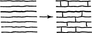
FIGURE 5.8 Depiction of cross-linked network.
As we have seen from the previous discussion, conventional polyethylene is composed of long chain polymers that, in turn, are composed of ethylene groups. The individual molecules are very long. The backbone may contain 10,000 to 60,000 atoms, sometimes more. Further, we have also seen that there are branches, crystalline and amorphous regions and that any additives or impurities must be residing in the amorphous regions—not in the crystalline regions. Cross-linking adds yet another dimension to the complexity of the molecular arrangement.
Figure 5.9 provides a description of how a conventional, non-XLPE “parent” (Figure 5.9a) is converted to the cross-linked “child” (Figure 5.9b through 5.9e). For simplicity, the chains (Figure 5.9a) are all shown adjacent to each other and are not coiled. The linear chains represent a simplified description to fit our purposes here. First, two adjacent chains link together (Figure 5.9b). We immediately see that the molecular weight has increased. The first cross-link leads to two branches. In Figure 5.9c, the first two chains have been simply redrawn from Figure 5.9b in a more familiar way. In Figure 5.9d, three additional cross-links have been (arbitrarily) added, two to different chains. The third shows that the newer (previously cross-linked) higher molecular weight chain is again linked to another chain. In Figure 5.9e, it has been redrawn (Figure 5.9d) to show how the cross-linking process looks as the chains are again “stretched out.” Note how the original two chains have dramatically increased in molecular weight.
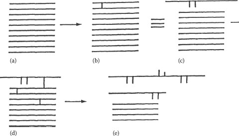
FIGURE 5.9 (a–e) Effect of cross-linking on chain length of polyethylene.
It should be clear from this description that the cross-linking process is a way of increasing the molecular weight, and this is exactly what occurs during this process. Note also that all the chains do not necessarily increase in molecular weight at the same rate. As the process continues (only the beginning of the process is depicted here), the molecular weight increases greatly that the XLPE can be considered to have an “infinite” molecular weight. A depiction of the polymer insulation crosslinked “wavy line” structure is shown in Figure 5.10.
One way of characterizing an extremely high molecular weight polymer as compared with a cross-linked polymer is to determine its solubility in an organic solvent such as toluene, xylene, or decalin [6]. A conventional polyethylene, even one of very high molecular weight, will dissolve in a heated solvent of this type. The solubility results from the chains moving apart in the heated solvent. XLPE will not dissolve. The chains do move farther apart when the cross-linked polymer is immersed in the warm solvent, but not so far apart so that dissolution occurs. What happens instead is that the XLPE merely swells in the solvent and produces a gel. Indeed, this is called the gel fraction. A simpler (qualitative) way to determine whether the polyethylene is cross-linked or not is to subject it to heat by placing the sample in contact with a hot surface. The conventional polyethylene will flow while the XLPE will resist flowing and behave more “rubbery.”
Commercial XLPE cable insulations also have a “sol” fraction. This is the portion of the polymer chains that never got incorporated into the “infinite” network. In Figure 5.9, we see some chains in (d) and (e) not incorporated into the network. The gel fraction of a commercial XLPE is about 70%–80%; i.e., about 70%–80% of the polymer chains are incorporated into the three dimensional gel network and the remainder are not and would be soluble in the heated solvent.
Another insulation material consideration is the number of cross-links between individual polyethylene chains. This is referred to as the molecular weight between cross-links and has theoretical significance [9]. (Swelling of the gel fraction diminishes as the molecular weight between cross-links is reduced; this results in increased “toughness” at elevated temperatures where crystalline melting has been significant.) However, for practical purposes, a 70%–80% total gel fraction is an adequate description. It is also common to refer to the “hot modulus.” This is a somewhat easier measurement to make than a sol fraction and does not involve the use of organic solvents. The hot modulus is directly related to the degree of cross-linking, or more correctly to the molecular weight between cross-links. It is greater as the degree of cross-linking increases or as the molecular weight between cross-links decreases. In the case of EPR (and elastomers in general), it is common to refer to “Mooney Viscosity,” which is a measure of the hot modulus.
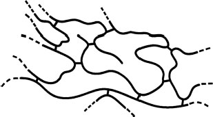
FIGURE 5.10 Cross-linked polymer showing coiled chains.
The next issue to consider is just how cross-linking of polyethylene (or copolymers such as EPR) is achieved. Cross-linking of the polyethylene chains can be induced by several different means:
• Use of organic peroxides
• Use of high energy radiation
• Modification of the backbone structure
5.4.2 PEROXIDE-iNDUCED CROSS-lINKING
Polyethylene that is cross-linked by peroxides (the most common method for medium voltage cables) contains a small amount of a cross-linking agent that is dispersed throughout the polymer. This agent is an organic peroxide, the most common being dicumyl peroxide [10]. Organic peroxides are chemicals that are stable at room temperatures, but decompose at elevated temperatures. There are many such peroxides available. Dicumyl peroxide is used commercially for medium and high voltage cables. It has traditionally been incorporated into polyethylene pellets by the material suppliers. When the polyethylene is extruded (conversion of the pellets into cable insulation), the peroxide remains stable due to the fact that its decomposition temperature is higher than the extrusion temperature. After the extrusion process, the polyethylene insulation surrounds the conductor and the conductor shield and is covered by the outer insulation shield; the cable now enters the long curing tube where the temperature is raised above the temperature employed in the extruder. At this higher temperature and pressure, the peroxide now decomposes and induces the crosslinking process. Peroxide-induced cross-linking uses a specific peroxide designed to intentionally decompose at a desired elevated temperature after the conversion of the pellets into cable insulation. The after-extrusion tube is called a curing tube, and the terms “curing” and “cross-linking” are often used synonymously. Note that this process takes place in the molten state of the insulation; i.e., the polymer (polyethylene) is heated to an elevated temperature high enough so that all the crystalline regions are melted while cross-linking is induced. The same process occurs with EPR.
A key component of the overall manufacturing of the cable is that the process must ensure that some degree of cross-linking does not take place prematurely. If this occurs, cluster(s) of oxidized polymer, referred to as “scorch” may form. These components can act as impurities in the sense that they will exhibit poor interfacial contact with the “healthy” polymer, which can therefore facilitate formation of microvoids. The latter in turn can lead to eventual premature failure. Scorch is avoided by proper control of the materials and processing conditions. Cable manufacturing is discussed in more detail in Chapter 11.
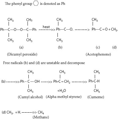
FIGURE 5.11 Decomposition of dicumyl peroxide leads to formation of volatile by-products.
When the peroxide decomposes during the curing process (Figure 5.11), it forms an active ingredient, called a “free radical,” which is unstable. The latter is so active that it interacts with any nearby molecule, which is virtually always the polyethylene chain. This free radical forms when the peroxide “splits” into an active oxygen-containing component that then “pulls” hydrogen atoms off the polymer chains. The polymer chain now becomes the active and unstable component and two such chains immediately combine to “cross-link” and also to stabilize the system once again. During this process, as the peroxide decomposes, and hydrogen atoms are pulled off the polymer chain, several by-products are ultimately formed. The major ones are dimethyl benzyl alcohol, acetophenone, alpha-methyl styrene, and methane.
These by-products form in the following manner. When the free radical (a cumyloxy radical) is generated, it can undergo several different types of reactions in its quest to become stabilized. It can “grab” a hydrogen atom from the polyethylene chain (as described above) and form the relatively stable dimethyl benzyl alcohol molecule. However, the unstable radical may also undergo internal rearrangement and “kick out” a methyl radical and become acetophenone. The unstable and highly reactive methyl radical may also pick off a hydrogen atom from the polymer, hence forming methane gas. Water may also be formed if the dicumyloxy radical expels a hydroxyl and a hydrogen radical, to form the water; it is then converted to alpha methyl styrene in the process.
The first three by-products of cross-linking (dimethyl benzyl alcohol, acetophenone, and methane) are always found in greatest quantities in XLPE. Acetophenone is a solid at temperatures lower than about 20°C. It emits a somewhat sweet odor, is not soluble in water, and is partially soluble in the polyolefin (the extent being dependent on the temperature). Due to its low melting point, acetophenone is a liquid at ambient temperatures. Dimethyl benzyl alcohol is also a liquid at ambient temperatures. These cross-linking agent by-products will remain in the insulation wall initially, but migrate out slowly over time. [There is some evidence that they impart some degree of water tree (and electrical tree) resistance to the insulation on aging.] Their chemical structures are shown in Figure 5.11 along with that of alpha methyl styrene; the figure depicts the chemical changes resulting from the cross-linking process. The methane gas evolved must be allowed to migrate out of newly manufactured XLPE-insulated cable after cross-linking has been accomplished. This is easily induced by allowing the cable to “sit” for a defined time after manufacture. Heating the finished cable shortens the time that is required. Other by-products, such as alpha methyl styrene, may be present in smaller concentrations. It should be noted that, at times, cumene is also found as another by-product; it is believed to develop from the further reaction of alpha methyl styrene.
It should be apparent by now that the peroxide-induced cross-linking process involves rather complex chemical reactions.
To achieve good cable insulation, the peroxide must be uniformly dispersed within the polyethylene. For appropriate uniformity of the cross-linking process to take place in the cable insulation, temperature and pressure must be properly controlled throughout the curing tube, which is quite long, but obviously of finite length. These factors contribute to preventing scorch, referred to previously.
It is important to emphasize that the cross-linking process described here also applies to mineral filled EPR, TR-XLPE, and cable shield materials all of which will also contain a peroxide. The same by-products are produced as long as the same peroxide is employed. It must not be forgotten that the carbon black-containing polymer comprising the inner and outer shields are also being cross-linked concurrently along with the insulation.
Dicumyl peroxide has historically been commercially available in several forms:
• Free flowing powders that contain about 40% active materials; the inert ingredients being calcium carbonate or clay
• As a 94% to 97% active, light yellow, semicrystalline solid
• A slightly more pure 98% active grade
The choice of dicumyl peroxide form is dependent upon requirements of the type of insulation being manufactured.
From what we have learned above, it is clear that peroxide-induced cross-linking takes place in the amorphous regions. Even though the crystalline regions cannot hold the peroxide in the original pellets, this is not a complication during the extrusion and cross-linking process since the crystalline regions necessarily melt during extrusion. By the time the peroxide induced cross-linking takes place in the heated tube after extrusion, the entire polymer is amorphous and the peroxide diffuses and is considered to be relatively uniformly dispersed. It should be emphasized that the complex series of reactions described above all take place within the melted but viscous polyethylene. When the cable is cooled down after extrusion and cross-linking, recrystallization takes place. When this occurs, the newly formed cross-linking agent by-products are “forced” into the newly formed amorphous regions.
XLPE gradually became the preferred insulating material of choice for medium voltage cable starting around the mid- to late 1970s and early 1980s (see Chapter 1). It replaced conventional low-density polyethylene (HMWPE) due to its superior high temperature properties and perceived better resistance to water treeing. Peroxide-induced cross-linking has been the prime method of curing for medium and high voltage cables as the process has been well developed and defined. For 69 kV transmission cables, peroxide-induced XLPE has also been an insulation material of choice. At higher voltages, peroxide XLPE has shared the market with conventional paper-fluid filled cables (These latter cables are not cross-linked.) As might be imagined, the thicker insulation walls of extruded transmission class cables require significant curing process modifications to ensure proper cross-linking.
Other peroxides also have been used; one is bis(tert-butylperoxy)-diisopropylbenzene (known as “Vul-cup”), which has a higher decomposition temperature than dicumyl peroxide. Higher temperature peroxides are of interest where it may be desired to manufacture the cable employing higher than conventional temperatures; the use of a higher decomposition temperature peroxide reduces the possibility of premature decomposition, which could potentially lead to processing problems. It should be noted that not all peroxides will decompose and induce cross-linking over the same temperature ranges. Finally, it should also be noted that most, but not all, of the peroxide necessarily decomposes during the normal curing process.
For low voltage cables (less than 600 V) peroxides may be used to induce crosslinking, but economic factors have allowed both silane and radiation induced crosslinking to share the market (see Sections 5.4.3 and 5.4.4). In this voltage range, it is not uncommon to employ conventional polyethylene since the voltage stresses and temperatures experienced by these cables are generally lower. Numerous additional polymeric insulation types are available, and cross-linking methodology may vary; see Section 5.11.
Again, although polyethylene has been used as the example for this discussion on peroxide-induced cross-linking, the same principles apply to the TR-XLPE and EPR polymers, which are cross-linked by peroxides in the same manner.
Once cross-linking has taken place, the polyethylene structure (which, as we have seen, was complex in nature to begin with) is now even more complex. Cross-linking typically takes place with about 70%–80% of the polymer chains being incorporated into the network, as noted previously. This means that 20%–30% of the remaining insulation is not cross-linked. Typically, this represents the low molecular weight fractions of the initial material (see Figure 5.3). The insulation of such cables that are installed therefore can be viewed as a mixture of LDPE and XLPE (or cross-linked TR-XLPE and a non–cross-linked portion; or cross-linked EPR and a non–cross-linked portion). However, the physical and dielectric properties are clearly dominated and controlled by the cross-linked regions of these insulations. At elevated temperatures, the XLPE cable insulation clearly maintains its form stability and functions as anticipated. For EPR, the low molecular weight sol fraction is the ethylene copolymer.
5.4.3 RADIATION-INDUCED CROSS-LINKING
It is also possible to cross-link polyethylene using high energy radiation instead of a peroxide. A beam of electrons emanating from special equipment can interact with the polymer chains, causing free radicals to form; a now-reactive polymer chain interacts with another chain (as described previously), hence inducing cross-linking. The electron beam serves the same role as does the catalyst peroxide. Radioactive isotopes such as Cobalt-60 can be used for the same purpose.
In the radiation cross-linking process, energetic electrons come into contact with the polymer chain and break the chemical bonds [8]. A ~C–H or ~C–C~ bond can be cleaved. When a ~C−H bond is broken, a hydrogen atom is released, and the now-highly energized ~C• polymeric free radical seeks to stabilize itself by combining with another like radical. This provides the cross-link. (The hydrogen atom can combine with another hydrogen atom to form a hydrogen molecule.) When a ~C–C~ bond is broken, it is apparent that this can, in principle, lead to a reduction in molecular weight; the shorter free radical chain can combine with another, or with a hydrogen free radical. Hence, the cross-linking and degradation processes compete with each other in radiation cross-linking. In actual practice, for polyethylene it can be generalized that approximately three cross-links form for every polymer chain cleaved, rendering the latter effect of little practical significance.
Radiation cross-linking involves different processing technology as compared with peroxide-induced cross-linking, and is employed primarily for low voltage cables. The radiation process is performed at room temperature, and therefore, for polyethylene, this means (unlike with peroxides) that cross-linking takes place while the polyolefin possesses both crystalline and amorphous regions. However, the insulation temperature can increase during radiation processing (depending on many factors), hence leading to some crystalline melting during the process. This complexity is “controlled” by applying this technology to thin wall insulations at high processing speeds.
The ambient temperature radiation-induced cross-linking process leads to some changes in the insulation not experienced via peroxide-induced cross-linking. First, the distribution of cross-linked regions will differ for the two processes. Second, when melting is not an issue if temperature is properly controlled, the nature of the crystalline regions after radiation-induced cross-linking remains about the same as before, i.e., no crystalline melting has occurred. This is unlike the peroxide crosslinking process, which is performed at elevated temperature, and where recrystallization occurs upon cooling. Finally, the radiation process induces certain chemical changes within the polyethylene not experienced during peroxide-induced crosslinking; this includes as a small amount of degradation products resulting from the radiation breaking a C–C bond, and other small changes on the polymer backbone. Also, no peroxide cross-linking agent by-products are produced. In addition, the use of multifunctional monomers to increase cross-linking efficiency and reduce cost is not uncommon [11].
Whether there are any practical consequences as a result of these differences is not relevant for medium voltage cable, as the radiation process has not been employed commercially for reasons noted. For low voltage wire cross-linking applications where speed of cross-linking is a key issue, radiation technology has been more applicable.
Another potential issue relating to this technology employing electron beams is the nonuniformity of dose (energy) absorbed for thick specimens and therefore the nonuniformity of the degree of cross-linking (gel fraction) as the wall thickness increases. There is an inherent radiation dose-depth relationship that is polymer thickness (film or coated wire) related, and the energy absorbed at different regions of a wire or cable wall will differ as the item being irradiated increases in thickness. The energy absorbed increases at first and then drops after reaching a maximum; the total dose absorbed is dependent upon the electron beam energy. Hence, the degree of cross-linking by electron beam technology is not uniform within the component thickness and much depends on geometry. It is not uncommon to apply a minimum dose in this type of situation or to irradiate from more than one side. This is in contrast to the relatively uniform degree of cross-linking that occurs with peroxides for medium voltage cables. This is not an issue for thin wall cables.
Use of radioactive isotopes, such as Cobalt-60, due to their greater penetrating capability (they emit gamma radiation), does not involve any nonuniform dose-absorbed issues, but Cobalt-60 usage involves a different set of manufacturing concerns, making it less useful for wire and cable cross-linking.
Radiation-induced cross-linking has also been successfully employed to manufacture polyolefin-based heat-shrink polymeric joints, and the crystallinity of the polymer is a key to the concept. In principle, the product is fabricated, cross-linked, heated and deformed (i.e., expanded at high temperature), and then cooled in the expanded state. The cooling process after cross-linking and intentional deformation by expansion causes recrystallization. The cross-linked and now-recrystallized component is indefinitely stable at ambient temperatures; it is provided to the customer in the expanded shape. When the cable joint is later applied in the field, externally applied heat causes the material to shrink by inducing crystalline melting, as it now seeks to regain the shape it had when it was manufactured. The heat shrink component wraps around and hugs the inner joint components tightly (including the connector). Cooling then facilitates the recrystallization process again, as we have seen. The joint now conforms to the shape of the equipment it covers.
The basic unit of radiation dose absorbed is called the rad (which is equal to 100 ergs/gm). Commercial applications require higher doses than rads, and are referred to in terms of grays, with 1 Gray (Gy) being equivalent to 100 rads. Older terminology in the literature refers to Megarads, and 1 Mrad = 10 kilograys. One Gray is equivalent to 1 joule/kilogram.
5.4.4 SILANE-INDUCED CROSS-LINKING
Another method of inducing cross-linking involves “moisture curing.” This concept employs organic chemicals called silanes (which are based on silicones) that react with water. In this process, cross-linking occurs at room temperature (but is accelerated by high temperatures). There are several specific approaches that have been applied in the past; this method does not involve the use of a curing tube or radiation equipment. For present-day silane-induced cross-linking technology, the polyethylene insulation has been modified, and is not a homopolymer.
A process called “Sioplas,” the first approach to applying this concept, involves grafting a silane monomer onto the polyethylene backbone using a peroxide catalyst (in essence, inducing a special type of branch) and also preparing a separate concentrate (batch) of polyethylene, an antioxidant, and another catalyst (dibutyltin dilaurate). These are then mixed in a specific ratio, extruded, and the completed wire or cable is then immersed in a water tank for a predefined time. Water induces a chemical reaction, leading to cross-linking. The process employs premixed components that require great care in storage. Another process called “Monosil” simplifies the overall procedure by mixing the polyethylene, catalyst, silane, and antioxidant together and then extruding the mix. The curing process is the same. A third silane-based cross-linking process involves the use of a polyethylene–silane copolymer (rather than a grafted material) [12], and allows the wire/cable producer to directly procure the silane-modified polyethylene; this simplifies the handling aspects. Again, the curing step is separate. The chemistry involves formation of ~C–Si–O~ bonds (in contrast to ~C–C~ bonds developed via the other cross-linking methods) [see Figure 5.12.]. The bond strengths are therefore somewhat different for the two types of cross-links, which leads to slightly different physical properties.
The curing process for all the silane technologies described above proceeds at a rate dependent on (a) water diffusion and (b) the insulation wall thickness. The water must penetrate the wall for curing to occur; hours to weeks may be required. Raising the water temperature increases the water diffusion rate into the insulation, and therefore the cross-linking (curing) rate; it is obvious that thinner cable insulation walls will cure more rapidly. However, different wall thicknesses of the same insulation material will ultimately cure (cross-link) to the same level, given adequate time. What is unique about the overall silane curing process, and makes it significantly different from peroxide or radiation curing, is that the cross-linking process may continue long after the cable is manufactured.
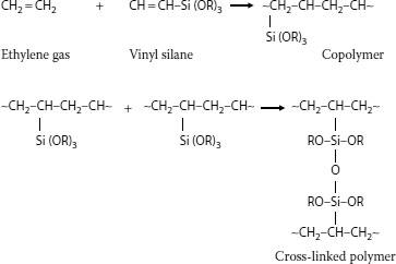
FIGURE 5.12 Ethylene silane copolymer cross-linking.
Due to the wall thickness influence on curing, the silane process has been commonly employed for low voltage (600 V) cables. It has been common to employ an outer layer of “tougher” polymer, such as high-density polyethylene over a silane-cured inner core, for certain applications where outer toughness and abrasion resistance are important.
Silane-induced cross-linking technology has also been applied for the purpose of upgrading aged, water-treed, installed polyethylene or XLPE cables. Here a silicone monomer is incorporated into the aged installed cables system, it migrates through the insulation wall, and then polymerization occurs in-situ (see Section 5.12).
5.4.5 TEMPERATURE INFLUENCE ON PROPERTIES
In view of the response of the semicrystalline polymers as a result of temperature changes under normal or overload operation, this subject is treated separately in this section.
Temperature plays a significant role in influencing the properties [11]. One of the properties of semicrystalline polymers that is of relevance for cable applications is that the crystalline regions have a tendency to “separate,” or move farther apart, as the temperature is raised. Chain separation converts the crystalline regions into amorphous ones, and is referred to as crystalline melting. Different crystalline regions will melt at different temperatures due to different degrees of “perfection” of the different crystalline regions. This manifests itself as melting over a broad temperature range (starting perhaps at about 60°C), but complete melting of the polyolefin does not take place until about 106°C. At this point, the structure is completely amorphous. While chain separation of the crystalline regions takes place as the temperature is raised and heat is absorbed, the molecules in the amorphous regions also move apart. (Amorphous regions undergo increased chain separation as temperature is increased even though no crystallinity is present.)
These principles apply to HMWPE and to XLPE, but recall that XLPE has a large gel fraction that cannot expand in the same manner as the non–cross-linked (sol) fraction, so thermal expansion is more limited and form stability is better retained.
Clearly, the ratio of crystalline to amorphous regions will change as a cable is thermally load cycled in service. Such chain separation also leads to thermal expansion and is more apparent in cables than in thin sheets. This fundamental phenomenon manifests itself in a nonuniform manner for full size cables under operating conditions (see Figure 5.13).
Focusing first on thermal properties of thin films or sheets of the polyolefin, it is easy to visualize a uniform response across the sample thickness. Here the change in crystallinity as a function of temperature would be uniform at any elevated temperature. However, such is not the case for cables that have thick walls relative to polymer films or sheets. Due to poor thermal conductivity of polyolefins, the effect of heating (from the conductor outward) on crystallinity is complex. The degree of crystalline melting varies, being greatest closer to the conductor and lesser as one moves toward the outer insulation shield. This is a result of the fact that the change in temperature is time-dependent and a thermal gradient exists across the cable wall. This manifests itself as a gradient of residual crystallinity, which will be dependent on cable wall thickness and varies as a function of time. Given enough time, an equilibrium will be established, but that does not mean that the temperature across the cable wall will be uniform.
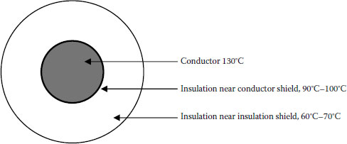
FIGURE 5.13 During thermal loading, cables exhibit thermal gradient across the wall.
Therefore, cables operating continuously at, say, 60°C will have a larger proportion of amorphous regions than a cable operating continuously at 30°C. The thermal gradient across the cable wall means that different amorphous/crystalline ratios will exist at different regions radially away from the conductor. Figure 5.13 demonstrates this principle. In this example, the temperature gradient results from the conductor temperature reaching 130°C. (This “overload” temperature is applicable for XLPE, not HMWPE; however, the objective here is to demonstrate the influence of the thermal gradient on crystallinity rather than the industry specification requirements.) Note that the temperature drops as the distance from the conductor increases.
Therefore, while the fundamental properties of semicrystalline polymers under thermal stress are significant and must be understood, practical application of such principles must be considered within the framework of real-world operating parameters.
This chain separation process leads to property changes such as reduction in physical properties (tensile strength, elongation, and modulus) and also a reduction in dielectric strength. When a cable that has been subjected to thermal overload (heated to elevated temperatures, defined in industry specifications as 130°C–140°C or greater) is later cooled down, the crystalline regions will reform, and the physical properties will now return to being closer to what they were originally. There are fine differences in the nature of the newly formed crystalline regions relative to the original structure, but the nature of these differences is beyond the scope of this chapter.
It is now easy to visualize that thermal load cycling induces even more complex dynamic changes within the cable wall.
Thermal overload is a subject that was of concern in the past; issues relating to thermal expansion (and interaction with accessories) were of concern, but these have been resolved.
At very low temperatures, other phenomena regarding chain motion take place. These phenomena are not as relevant to real-world functioning of cables as is the influence of elevated temperatures, and are summarized in Appendix A.
Another thermal issue relating to the response of polymeric materials employed as cable insulation (whether or not they are semicrystalline) refers to the role of antioxidants. This is not related to crystalline melting, but to assisting in maintaining properties by interfering with the thermally induced degradation process.
When the cable insulation temperature is raised during manufacturing, it will be susceptible to oxidative degradation. Under these conditions, the polymeric insulation is subjected to temperatures significantly higher than it will ever see in service. As a result, there is virtually always an extremely small amount of oxidation product (carbon–oxygen bonds) in the polyethylene structure that cannot be prevented during the extrusion process. Oxidative degradation, if significant, may be particularly harmful as it can lead to chemical changes within the insulation that introduce more polar materials, which may, in turn, introduce changes in the electrical properties and make the cable more prone to failure during aging. To inhibit this potential degradation mechanism, small amounts of another material called an antioxidant are incorporated into the polymer pellets [13,14]. For medium voltage cables, the common types have historically been either organic amine based or phenolic compounds. Other types, such as phosphites, have also been used. The antioxidant preferentially decomposes in the extruder under the thermal environment and inhibits or prevents decomposition of the polymer. The antioxidant can be considered as a sacrificial component that facilitates high quality product during cable manufacturing.
The antioxidant also resides in the amorphous regions of the polymer at the beginning of the extrusion process, and when crystalline melting occurs as the temperature increases, it can migrate throughout the wall. Upon cooling of the XLPE after manufacture, any unreacted antioxidant would reside in the amorphous regions. Also residing in the amorphous regions will be any antioxidant degradation by-products that are not volatile. This is common for all extruded cross-linked medium voltage insulations.
There are many antioxidants available commercially. In the past, polyethylene-based cables were categorized as “staining” or “nonstaining;” amine types are yellowish in color and phenolics are white. Analytical chemistry techniques can be employed to evaluate antioxidants. Any specific antioxidant employed can generally be determined by obtaining an infrared spectrum of a thin film of the polymer; the antioxidant efficiency, a measure of the amount of “activity” of the antioxidant, can be estimated by an oxidation induction time measurement via thermal analysis. Formation of minute amounts of oxidation in polyolefin insulation during extrusion is not completely preventable, but is kept to an absolute minimum by appropriate processing conditions.
For relatively new or unaged cable systems, very long aging times at high temperatures are required to induce thermal degradation [14]. When changes do occur under dry aging, the property loss is in the direction of: (a) oxidation resistance, (b) physical property change in elongation, and finally (c) electrical properties such as dielectric strength. These changes did not affect the reliability of XLPE cables under thermal overload. [For aged cables that possess water trees, the direction is first (a) electrical properties such as dielectric strength, and then (b) elongation and (c) oxidation resistance.]
By now, it should be clear that polyethylene is a very complex material. Its apparent simplicity, a composition consisting solely of repeating −CH2− functional groups, belies the fact that the actual polymer is composed of segments imparting quite different properties. The alignment of some of the chains imparts crystallinity; the nonaligned fractions can coil and are called the amorphous regions; chain branches influence crystallinity; different polyethylenes have different degrees of crystallinity and also different molecular weight distributions. The polymer itself is therefore a “mixture” of different physical segments. That is why it is referred to as “semicrystalline.”
The amorphous regions, having “large” distances (on a molecular level) between the polymer chains relative to the crystalline regions, are sites where foreign ingredients can reside. Such foreign contaminants may include ions and cross-linking agent by-products (see Section 5.4). The crystalline regions, where aligned chains are closer together than in the amorphous regions, are the regions that resist foreign ingredient “settlement” and also penetration of most gases. The crystalline regions provide the toughness and resistance to environmental influences. However, without the presence of the amorphous regions, it would not be possible to extrude the polymer into a functional insulation.
One question that arises is what causes different polyethylenes to have different ratios of crystalline to amorphous regions. Any component present in the polymer chain (backbone) that interferes with chain alignment will decrease the degree of crystallinity. Hence, a copolymer of ethylene with propylene, EEA or EVA (as examples), will decrease the number of consecutive methylene links in the chain and increase the tendency for the chains to be more amorphous. This suggests that EPR would be less crystalline than polyethylene and that is exactly the case. The extent to which this occurs is dependent upon the E/P ratio present. As the amount of comonomer increases in the polymer, there is a progressive decrease in crystallinity. One may wonder, therefore, how the “lack” of crystallinity (which imparts “toughness”) is compensated for in a completely or almost completely amorphous polymer. The answer is that inorganic fillers need to be added in order to provide the required “toughness” in amorphous insulations (see Section 5.6).
A second factor contributing to influencing the degree of crystallinity is, as noted earlier, the tendency for the chains in homopolymers to have branches. The older conventional high-pressure process of manufacturing polyethylene (from ethylene monomer) facilitates the formation of numerous branches on the backbone. The branches can have different chain lengths themselves. This is depicted in Figure 5.4. It is the number of branches and their lengths in conventionally manufactured polyethylene that influence the tendency to align and, in turn, influence the density and crystallinity. It is for this reason that there are such a large variety of different densities of polyethylene available. It is apparent now that the propylene portion of EPR can be considered to represent very short length branches.
Until the mid-1980s, high molecular weight low-density polyethylene was the commonly used medium voltage insulation material for many users. This polymer has been superseded for new installations, first by XLPE and then by other materials such as EPR and tree-resistant XLPE. Medium- and high-density polyethylenes have traditionally been used as components for cable jackets in low and medium voltage cables.
5.5 TREE-RETARDANT CROSS-LINKED POLYETHYLENE
Over the years, numerous attempts have been made to improve the performance of conventional polyethylene and XLPE in order to attain increased life. In the past, when HMWPE was the insulation of choice, dodecyl alcohol was employed as a tree-retardant additive to HMWPE. When XLPE was first developed, it was reported that one of the cross-linking agent by-products imparted tree-resistant properties to the insulation (acetophenone, which evolves from the decomposition of dicumyl peroxide, see Figure 5.11). Later work focused on improving the tree resistance of XLPE by employing technology not related to the cross-linking agent.
There are several fundamental approaches that are applicable, the basic concepts being either altering of the polymer structure itself, or incorporating additives to a nonaltered structure (or both). Since these approaches would render the polymer more polar (nonpolarity is a desired property of cable insulation, see Chapter 6), a delicate balance of property changes would be required. Such changes would therefore need to first be considered from the framework of the physicochemical goals being sought and what such changes would produce. Hence the following considerations are necessary (as elegantly summarized by Jow and Mendelsohn) [15]:
1. Reducing localized region stresses
2. Introducing a barrier to water tree growth
3. Imparting some level of elasticity to the polymer insulation
Modification of the polymer structure or incorporating superior additives would involve applying these concepts. From this perspective, one could seek:
1. A more polar “backbone” or polar additives that could absorb water and prevent migration toward high stress sites, hence inhibiting water tree growth
2. Employing low molecular weight additives (superior to acetophenone) to prevent treeing
3. Seeking a polymer blend that could facilitate increased elasticity
While specific methods for achieving tree-retardant cable materials is a proprietary arena, one can assume that the principles described here are what has been/is being employed in order to achieve the desired goal [3].
The modified XLPE is usually tested first as a pressed slab (or as extruded miniature thin wall wires) to ensure that improvements have indeed occurred. However, it should be noted that the key method for ensuring that the modified insulation material is indeed tree retardant is to perform tests on completed cable constructions; the accelerated cable life test (ACLT) or accelerated cable water treeing test (AWTT). This means that one ultimate tree-retardant material test is evaluation in conjunction with the shields (and possibly jackets).
The first commercial TR-XLPE material was made available from Union Carbide (now Dow Chemical Company) in the early 1980s. [The original patent literature discloses that a mixture of additives is likely to be present.] Historical information from field aging combined with laboratory data has clearly demonstrated the superiority of TR-XLPE over conventional XLPE.
Table 5.1 provides a simplified summary of comparative material components of conventional and tree-retardant XLPE. The major difference is in the initial ingredients and also potential additional by-products of the cross-linking reaction.
TABLE 5.1
Comparison of XLPE and TR-XLPE Cable Insulation Materials
XLPE Insulation |
Tree Retardant XLPE Insulation |
XLPE |
XLPE |
Intentional tree-retardant additive(s)—No |
Intentional tree-retardant additive(s)—Yes |
Residual amounts of dicumyl peroxide |
Residual amounts of dicumyl peroxide |
Cross-linking agent by-products |
Cross-linking agent by-products |
Acetophenone, cumyl alcohol, and alpha-methylstyrene |
Acetophenone, cumyl alcohol, and alpha-methylstyrene |
Other additives—No |
Other additives—may be |
Antioxidant |
Antioxidant |
Antioxidant degradation by-products |
Antioxidant degradation by-products |
5.6 ETHYLENE COPOLYMER INSULATIONS (EPR)
EPR is a copolymer (see Section 5.2.5) composed of ethylene and propylene [2]. The ratio of E/P can vary over a wide range, but in practice, commercial cable insulation is composed of different EPR copolymers having ~50%–80% ethylene. This copolymer has significantly different properties as compared to polyethylene, XLPE, or TR-XLPE, while providing the dielectric characteristics required for low and medium voltage cables. Perhaps most significant is the fact that the propylene segments in the polymer chain interfere with the natural tendency of the polyethylene chains to align and crystallize (see Section 5.2.4). While EPR copolymers are composed of polymer chains of varying molecular weights, and have branches (much like as described for polyethylene), the lack of crystallinity renders it relatively soft and extremely flexible (unlike polyethylene). As with polyethylene, EPR may have “high” or “low” molecular weight molecules and broad or narrow molecular weight distributions. Hence, there are many grades available, each having different properties.
Figure 5.14 depicts one molecule each of ethylene and propylene. A copolymer of this composition would yield a polymer that contains 50% of each monomer. The polymer molecular structure shown in the lower portion of the figure represents an approximation of what the branched polymer structure would look like, with the propylene (methyl groups) branching out from the backbone. These short chain branches are sufficient to prevent crystallization and this EPR copolymer would be soft, flexible, and lacking in stiffness.
It can be visualized that if the ratio of E/P was increased, there would be greater distances between the small branches due to the propylene presence. This is what happens when the ethylene ratio is increased to the ~70%–80% range. In those cases, it is easier for segments of the polymer chains to align and crystallize, and those EPRs can be referred to as being “semicrystalline.” Indeed, the higher the ratio, the greater the small segment chain alignment and the greater the crystallinity of the EPR copolymer. In actual fact, however, even the highest level of crystallinity in practical EPR insulations is at most only about 10% of that which is present in conventional low density polyethylene (LDPE). As a result, the level of “stiffness” in any EPR does not compare with that of any conventional LDPE (or XLPE or TR-XLPE). (Comparison with LLDPE or HDPE is therefore irrelevant.)
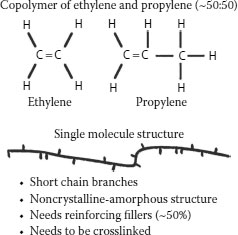
FIGURE 5.14 Copolymer of ethylene and propylene (~50/50 E/P ratio).
EPR materials are known as elastomers. Elastomers are soft polymers and as a class also include natural rubber, synthetic rubber, and butyl rubber (all of which were employed as cable insulation prior to the development of EPRs; see Chapter 1). This class also includes Neoprene, Hypalon, and PVC. Conventional elastomers have significantly different properties than semicrystalline polymers. Reduced crystallinity means that the desirable properties imparted by the crystallinity are minimized or missing altogether: modulus (or “toughness”) and high tensile strength of the polymer are examples of properties that have been reduced. This means that a functional insulation that is analogous to HMWPE cannot be produced with a pure, ethylene–propylene copolymer (even if it were cross-linked). A pure EPR copolymer neither has the physical properties required to perform as a functional insulation, nor it could be extruded into cable form. While the electrical properties (e.g., dielectric losses) are low and desired (as with polyethylene), the ability to apply the good properties requires that the EPR copolymer be modified with additives. These additives improve the physical and mechanical properties but are not helpful to electrical properties (such as dielectric losses).
It is important to note that the absence or minimization of crystallinity produces a beneficial side effect; there can be no thermal expansion on heating due to crystalline melting. There will be minimal thermal expansion due to chain motion at elevated temperatures as occurs with polyethylene above the melting range (>106°C).
The required inorganic mineral filler additives in an EPR compound serve various roles; some serve to toughen the system by improving the physical and mechanical properties (and are referred to as reinforcing), while others serve to facilitate processing [16]. Silane-coated calcined clay is the common reinforcing filler employed in EPRs. Also the EPR resin must be cross-linked to render it suitable as an insulation material. If it were not cross-linked, even mineral-filled EPR would not be capable of serving as cable insulation.
In addition to inorganic mineral fillers, many additional components are also required to allow EPR to be useful as insulation. These are mixed with the polymer, and the blend is now generally referred to as a “formulation” or “compound.” All the additives (there may be 10 to perhaps 20) are incorporated using special mixing equipment. Therefore, the EPR polymeric material is the only component in the eventual cable insulation. The method of mixing the ingredients together is referred to as a compounding process. It must be noted that many of the ingredients present in EPR compounds that are used as insulations for cables are considered proprietary by some organizations and the exact formulations are not published. However, that is not universal, and Table 5.2 shows typical EP formulations supplied commercially in the past, up until around the late 1990s. The components, approximate amounts, and their purpose are described.
TABLE 5.2
Typical EP Insulation Compounds Employed Until the Late 1990s (in Parts per Hundred)
Ingredient |
Amorphous |
Semicrystalline |
Nordel 1040 (amorphous) |
100.0 |
— |
Nordel 2722 (semicrystalline) |
— |
100.0 |
LDPE |
— |
5.0 |
Zinc oxide |
5.0 |
5.0 |
Red lead (90% dispersion) |
5.0 |
5.0 |
Silane treated Kaolin |
120.0 |
60.0 |
Vinyl silane A-172 |
1.0 |
1.0 |
Process oil |
15.0 |
|
Paraffin wax |
5.0 |
5.0 |
Antioxidant |
1.5 |
1.5 |
Dicumyl peroxide |
3.5 |
2.6 |
• EPR: The base material that forms a continuous phase in which all the ingredients noted here are uniformly dispersed. The polymer provides flexibility and good electrical properties. All amounts shown are based on 100 parts of the polymer. The two EPR polymers noted have been described as being either amorphous or semicrystalline.
• Low density polyethylene: A small amount is added to a formulation of EPR compound employed in “semicrystalline” EPR.
• Zinc oxide: A traditional component in EPR and EPDM compounds that improves thermal stability. ZnO was initially incorporated into cable insulation in the past, as it was employed in EPR compounds for automobile tire applications.
• Red lead: Lead oxide (Pb3O4) serves as an ion scavenger. It improves electrical properties under wet aging. It was incorporated into EPR compounds many years ago to meet low voltage cable test requirements.
• Silane-treated Kaolin (clay): This inorganic mineral is a coated calcined (heat treated) clay that serves to improve the mechanical properties of the formulation. Since the rubber material has little or no crystallinity, the filler imparts mechanical strength. The clay is coated with a silane to improve polymer–filler interaction at the interface of the particles with polymer. If the clay was not coated, “gaps” could develop at the interfaces, leading to poor properties. On a microscopic level, the filler particles are large compared to the polymer chain.
• Vinyl silane: Additional silane is often incorporated to ensure adequate polymer–filler interfacial contact.
• Processing aids: A wax or oil that serves as a lubricant since the inorganic additives are “abrasive” in nature.
• Antioxidant: This serves the same role as it does in polyethylene or XLPE; to prevent polymer decomposition during extrusion.
• Dicumyl peroxide: This is the cross-linking agent and serves the same role as it does in XLPE. All EPR compounds must be cross-linked to be useful as insulation. The peroxide-induced cross-linking process is exactly the same as for medium voltage XLPE cables (although the extrusion rates may differ).
As noted previously, individual compound manufacturers, or cable manufacturers who perform compounding, may incorporate additional proprietary ingredients in their commercial EPR formulations. The exact nature of these ingredients may vary. Hence, different antioxidants, process oils, or waxes may be used. Some additives can serve multiple purposes such as to further enhance processing, enhance aging properties, or modify dielectric properties. The entire compounding process becomes more complex when one considers other factors, one being the particle size and shape of the clay component.
Mixing of the ingredients in an EPR formulation is an art as well as a science. It is more complex than the technology for mixing ingredients into polyethylene, and the history of mixing ingredients into elastomers predates the use of EPR. The key for achieving satisfactory EPR compounds suitable for later extrusion (along with proper components) is uniformity and control of mixing parameters. Mixing technology employs either a batch process employing a Banbury mixer, or a continuous process employing a Buss kneader. Both technologies facilitate proper mixing of ingredients without degrading the polymer, but the technologies differ.
The Banbury process involves the use of a conveyer belt to carry preweighed ingredients into the mixer and has been described as a high intensity batch mixing process. It is an internal mixer that employs spiral shaped blades encased in segments of cylindrical housings. These intersect to leave a ridge between the blades, which may be cored to provide heating or cooling capability. Under elevated temperature, the heated elastomer is allowed to mix with the additives under controlled conditions. Along with inducing dispersion and preventing agglomeration of the organic and inorganic components, it is equally important to prevent premature cross-linking (commonly referred to as “scorch”) and therefore parameters under control include mixing time, temperature, as well as the order of additive incorporation. Rotor design induces satisfactory mixing by employing high shear followed by intimate mixing. The Banbury process has a long successful history of usage with elastomers [17].
The Buss kneader is a continuous single step (not batch) mixing process; additives are incorporated directly into the molten polymer at controlled temperatures. Injection of liquids directly into the molten polymer can be performed. While the batch process predates the continuous mixing process by many years, continuous mixers have been claimed to provide certain advantages, uninterrupted operation being the most obvious: claims include: (a) facilitating improved heat transfer (due to greater surface to volume ratio); (b) availability of interchangeable parts (facilitating increased versatility); (c) holding a portion of the load of a batch mixer at any one time, while producing product at the same rate; and (d) precise temperature control [18].
Regardless of the mixing technology employed, the key involves attaining proper dispersion at acceptable rates without inducing degradation. [It can also be noted that these principles apply to all cable systems requiring mixing; other examples include peroxide addition to XLPE or TR-XLPE, semiconducting carbon black in polyethylene, and also flame retardant additives into low and medium voltage formulations.]
5.6.2 ADDITIONAL EPR CONSIDERATIONS
1. Sometimes, it is desired to add a third monomer to the ethylene–propylene monomer blend prior to polymerization. These polymeric materials are called EPDM and have been used to facilitate certain (nonperoxide) cross-linking processes. The E refers to ethylene, the P refers to propylene, and the D refers to diene. The reference to M, however, has changed over the years. EPDM has previously been referred to as ethylene–propylene–diene–monomer, and also as ethylene–propylene–diene–methane. Today, M refers to its classification in ASTM standard D-1418. The “M” class includes rubbers having a saturated chain of the polymethylene type.
2. The dienes possibly used in the manufacture of EPDM rubbers are dicyclopentadiene (DCPD), ethylidene norbornene (ENB), and vinyl norbornene (VNB). These dienes typically comprise 2.5 wt% up to 12 wt% of the composition.
3. EPRs that have the higher percentage of ethylene are pelletized; those that have lower levels of ethylene are provided as strips and fed into the extruder. Again, due to their overall lack of crystallinity, cables employing any EP compound will have reduced thermal expansion as well as lower heat capacity and higher thermal conductivity as compared with XLPE (or TR-XLPE). Processing of pelletized (i.e., higher E/P ratio) medium voltage EPR insulated cables is performed on the same equipment used for XLPE or TR-XLPE. Steam or dry curing may be employed, although steam curing has traditionally been more common for EPR.
4. Compounding of EPR (i.e., mixing of all the required ingredients) may be performed by the cable manufacturer, or may be performed by a separate organization that provides the finished compound to the manufacturer. In the past, components in an EPR that were compounded by a commercial supplier had been made public; cable manufacturers may keep their compositions proprietary.
5. While the added ingredients impart the desired mechanical and physical properties to the EP compound, they do have a detrimental effect on initial dielectric properties. The dielectric losses (dissipation factor and power factor) and dielectric constant all increase. This magnitude of the increase will differ as the nature of the EP compound changes (see Section 5.6.3 and Chapter 6).
6. In the past, some medium voltage EPR compounds were provided with carbon black mixed as one of the ingredients in the insulation; this is not the present-day practice.
7. Inorganic clay fillers are an integral part of the EPR formulation. The handling and treatment of the clays have been modified and improved over the years. Clay can be described as being hydrous (possessing moisture, as received), calcined (heat treated), or coated (heat treated and modified by an organosilane). Present-day EPR compounds employ the latter, while older insulations such as butyl rubber employed calcined clay. Factors influencing clay effectiveness include particle size, (i.e., surface area exposed to the polymer), the degree of interfacial contact with the polymer, and the clay structure itself.
5.6.3 ALL ETHYLENE–PROPYLENE RUBBERS ARE NOT ALIKE
As we have noted, different EPR compounds employed as cable insulation are composed of ethylene and propylene having different ratios in the chain length (also referred to as “backbone”); these differences influence the flexibility. In addition, the compounds contain a plethora of different ingredients varying in nature and concentration, and which are required in order to render the soft EPR polymer useful as insulation. It is not surprising, therefore, to expect that different EPRs would respond differently upon aging, even assuming identical or optimum mixing and extrusion conditions. Indeed, the differences in additives (nature and concentration) along with the EP ratio are what impart different characteristics to EPRs suitable at different voltage levels (say secondary vs. primary or feeder cable). These changes are what render different EPRs suitable to meet different industry specifications.
However, what is being referred to here are differences upon field or laboratory aging for different EPRs employed for medium voltage cables that have met industry specifications. The literature contains many reports of the differences in response on aging. Unfortunately, the literature does not always report the ingredients present in the EPRs studied.
It is worth making a comparison with XLPE, which has only three ingredients: polyethylene, cross-linking agent, and antioxidant. No host of additives to impart “toughness” or compatibility or complex mixing technology is required. One might anticipate that any difference in response on aging of a single compound might be related to the extrusion processing, rather than the nature and mixing of the ingredients (all other things being equal).
A few examples are noted as follows:
Bartnikas [19] refers to different dielectric loss characteristics for three different EPRs as a function of frequency. (Electrical properties of polymeric materials are discussed in Chapter 6.)
The elastic modulus and thermal expansion of different EPRs have been demonstrated to differ as the temperature increases. Differences between four different EPRs in thermal conductivity (resistivity), heat capacity, thermal expansion, and weight loss (on heating) have been reported [20].
A full size cable study by Cable Technology Laboratories provided conclusive evidence; in that study, five different commercially available full size EPR cables were aged both in the field and in the laboratory under both normal operating stress and under accelerated voltage stress [21].
Significant differences were observed. To demonstrate the point, Figures 5.15 and 5.16 show the responses of the different EPRs. In Figure 5.15, the EPRs aged for 24 to 48 months under normal operating stress show that the retained dielectric strength varies extremely widely; from 40% to 100% between the different EPRs. (Changes in aging response up to 70 months are also shown.) Similar differences are shown in Figure 5.16 for the same cables aged under accelerated voltage stress in the laboratory.
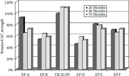
FIGURE 5.15 AC breakdown stress retention of EPR cables laboratory aged at 1.0 Vo.
5.6.4 DISCHARGE FREE VERSUS DISCHARGE RESISTANT
A good example illustrating the fact that all EPRs are not alike is represented in the manner by which long life is achieved. Up until now, we have focused on technology designed to prevent partial discharges (see Chapter 6) in the insulation wall and maintain low dielectric losses. This is achieved by ensuring that the insulation is clean (no foreign contaminants), does not possess voids, and is of low polarity. Another goal is to ensure that these properties are maintained upon aging. This philosophy applies to all polyolefins (HMWPE, XLPE, TR-XLPE, as well as EPR). In the case of EPR, where we have seen that there are many required components that are absent in the semicrystalline polymeric insulations, the use of additives that would increase the dielectric losses is intended to be minimized, as some increase in losses is unavoidable. The goal of this approach is to achieve EPRs that are discharge free.
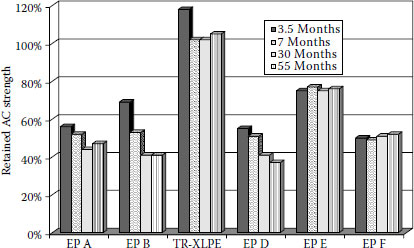
FIGURE 5.16 AC breakdown stress retention of EPR cables laboratory aged at 2.5 Vo.
Another approach in developing long-life EPR formulations turns the methodology around. The alternate approach assumes that it is not consistently possible to achieve the goals described above after significant aging, and seeks to provide an insulation that operates reliably under partial discharge conditions (i.e., is not degraded on aging); hence it is considered to be discharge-resistant rather than discharge-free. Therefore, the additives in the EPR polymers that follow this approach are different in nature.
Although the specific additives employed to achieve this goal are proprietary, the principles involved can be noted. Such additives can serve the role of: (a) imparting high dielectric constant (see Chapter 6) to the insulation; and where the additives can also (b) migrate toward any voids that develop upon aging and can increase the surface conductivity of the voids; and (c) trap high energy electrons that could cause partial discharge and thus dissipate the energy as heat. This philosophy intentionally increases losses to improve service aging performance. The choice of additives to the EPR and the method of compounding (to achieve this goal) is made by the cable manufacturer, and the insulation has been described as a “proprietary EPR/EPDM based compound” [22].
Clearly, the ability to incorporate a wide variety of additives into an elastomer like EPR increases the capability for designing the compound to meet specific goals. Ultimately, a goal is to compare the semicrystalline XLPEs and the EPRs; a fundamental paper in this regard has been provided by Eichhorn [23].
5.7.1 OVERVIEW AND ROLE OF THE POLYMER
Polymers employed in formulations used as cable shields are based on ethylene copolymers. They may be copolymers with propylene or with other monomers such as EVA, EEA, or butyl acrylate (EBA). In essence then, they are “elastomers.” Each of these individual comonomers imparts different properties to the copolymer employed in the shield. As with insulation, one must consider molecular weight and molecular weight distribution issues, extrusion characteristics, and with cross-linked insulations the shields must also be cross-linked; however, crystallinity is not an issue. Carbon black is present (see Section 5.7.2) and influences both processing and properties.
Strand shields are employed over the conductor and under the insulation, and insulation shields are extruded over the insulation itself and interface with the concentric neutral or metallic tape and (depending upon construction) any jacket that may be present. These shields must be semiconducting in nature, as they provide a “stress gradient” between the insulating and conducting layers, and the intention is to achieve a discharge-free system. While the semiconducting (electrical) properties of materials employed for either strand or insulation shields are similar, their physicomechanical property requirements differ. Hence, the insulation shield must be strippable (for ease of removal at the region where the joint or termination must be installed), yet the strand shield must exhibit the opposite property; it must adhere strongly to the insulation surface at the conductor region (to prevent void formation and water penetration). The modulus and tear strength of the insulation shield are critical parameters, as well as the cohesive strength so as to not allow “pick-off” during stripping, and this is controlled by the copolymer nature, additives, and processing.
Semiconducting properties are achieved by incorporating a conducting carbon black into the copolymer. By employing the appropriate carbon black and proper handling, the carbon black–filled polymer is rendered semiconducting in nature. Carbon black terminology refers to “furnace black” or “acetylene black;” furnace black is prepared by partial oxidation of oil or gas, while acetylene black is prepared by decomposition of acetylene at elevated temperatures [24]. Along with conductivity, the required characteristics of the carbon black include surface smoothness, particle size control, proper dispersion in the polymer, and purity.
It has been known for a long time that the properties of carbon black–filled elastomers are strongly influenced by numerous factors: (a) the nature of the carbon black, (b) the concentration of black employed, (c) the type of base polymer, and (d) the cure (cross-linking) system used [25]. The latter is not a present-day issue, but the other points remain relevant.
Conductivity is achieved when the carbon black forms aggregates within the polymer matrix, leading to a continuous path that allows electron flow. The details of this technology are beyond the scope of this chapter, but it can be noted that electron “tunneling” from one aggregate to another leads to the conducting properties required in the semiconducting layers. The eventual electrical properties of the semiconducting shield material are controlled by the structure of these aggregates and by the size of the carbon black particles comprising the aggregates. Figure 5.17 demonstrates how this relationship influences physical and electrical properties [24].
Carbon blacks with high structure tend to impart greater conductivity and hardness–structure referring to the ability of the carbon black to aggregate into clusters (as shown in Figure 5.17). The structure can be disrupted when incorporating the carbon black into the elastomer, the extent being determined by the type of black and the mixing process, so proper control is a key issue. The carbon black concentration in a semiconducting shield copolymer will be dependent upon the type of carbon black employed; it may be in the 12%–30% range.
Surface smoothness is necessary so that there are no protrusions (due to mechanical imperfections or poor dispersion) at the region that interfaces with the insulation; these can represent high stress sites from which water tree growth can develop in wet environments. When present at the semiconductive shield interface, protrusion effects are influenced by the carbon black geometry (the tip radius or sharpness) and their height. Hence, the degree of dispersion of the carbon black and its “fineness” in the completed cable are key factors in achieving surface uniformity and smoothness. Proper dispersion of the carbon black in the polymer along with the need for proper mixing and handling is an obvious requirement.
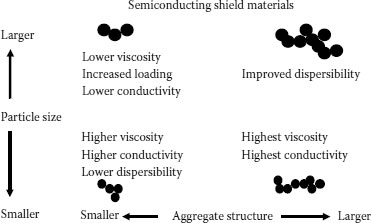
FIGURE 5.17 Effect of carbon black particle size and agglomerate structure on properties.
Impurities are a major concern; after preparation, the carbon black may possess small quantities of moisture, sulfur, and inorganic salts. Sulfur can harm the electrical properties, and most of the inorganic salt content comes from the water used for quenching and pelletizing during the manufacturing process [26]. Inorganic ions had been a significant concern in the past. The furnace blacks commonly employed until about the mid-1980s (due to the nature of the processing) had higher levels of inorganic ionic contaminants as compared with acetylene blacks; this led to increased failures due to water treeing. More recently, furnace blacks of increased cleanliness have been employed; this is noted here as many older installed cables possess such older black in their shields.
It is also possible to incorporate additional additives. For example, controlled strippability of insulation shields (for ease of removal) may be achieved with additional additives, but such additives would not be used for conductor shields where strippability is not desired.
Finally, carbon black–containing shield materials must be extrudable and cross-linkable as easily as the insulation, and under such conditions that “true triple” extrusion can be effectively performed with the semiconducting electrical properties remaining in the desired range. Factors that influence the conductivity are the carbon black type and concentration, processing conditions, the cure system, and other components present. The base polymer type is significant; e.g., for strand shields, combinations that have been employed are: (a) furnace black with EVA or EEA copolymers, and (b) acetylene black with EVA or ethylene butyl acrylate (EBA) copolymers.
5.7.3 NONCONDUCTING SHIELD MATERIALS
It is possible to design shield materials that are nonconducting (rather than semiconducting). The polymer employed is based on EPR and the additives that are incorporated into the EPR are proprietary. The required properties are achieved by ensuring that the additives impart the property of high dielectric constant (see Chapter 6) to the shield. These shield compounds are employed in conjunction with insulation materials that are designed to be discharge-resistant (rather than discharge-free, see Section 5.6.3.1). In essence, when considering the conductor shield, the stress control layer that is designed to reduce the stress at the interface of the conductor and the insulation achieves this goal by a different mechanism than do the shields discussed in Section 5.7.2 [27].
Jackets are extruded over the completed cable core and their metallic shields or neutral wires to provide mechanical protection (abrasion and puncture resistance) and to protect the cable from the local environment. Objectives also include protecting the neutrals from corrosion, and specifically, to prevent moisture penetration. Good environmental stress-crack resistance is also a requirement. Common jackets are insulating, and ideally, they will aid in keeping not only water out of the insulation but also contaminants and foreign ions. Jacketing materials have varying properties that are controlled by their molecular structure and compound ingredients.
Insulating jackets contain small quantities of carbon black that is not conducting (i.e., different in nature from that employed in shields).
For medium voltage cables, several polyethylene types have been commonly employed as jacketing materials:
• LDPE
• MDPE
• HDPE
• LLDPE
It is clear by now that the differences are in the degree of “chain alignment” that takes place, and that HDPE is more crystalline than is LDPE (see Section 5.2.4); the higher the degree of crystallinity, the higher the density. As the name implies, MDPE is “in-between” the other polyethylene grades with reference to the degree of crystallinity. HDPE is manufactured by a different catalyst and pressure control as compared with the LDPEs and MDPEs employed for cable applications. It possesses a higher degree of crystallinity and greater toughness and abrasion resistance, but the extrusion process is more complex. LLDPE is manufactured in such a manner that it approaches HDPE in properties, but the ethylene monomer is polymerized by a different method than conventional LDPE, employing catalysts, and is more easily processed as compared with HDPE. Properties considered during processing and application of jacket materials include abrasion resistance, stress-crack resistance, melt flow rate, and prevention of shrinkage. In practice, LDPE was commonly employed in the past and has gradually been replaced by LLDPE. HDPE has been used in special applications as determined by the user.
It should be noted that VLDPE (density range of 0.880–0.915 g/cc), a linear metallocene-produced copolymer of ethylene and alpha-olefins such as 1-butene, 1-hexene, or 1-octene is commercially available. It possesses short chain branches much as does LLDPE.
More recently, Polypropylene has come into usage as a cable jacket, as a result of new catalyst technology facilitating polymerization. Polypropylene is “tough” but has a significantly different architectural crystalline structure from polyethylene and as a result, possesses lower density. Because of its increased toughness, it is a good jacket material, comparable in some respects to HDPE despite the lower density. Polypropylene extrusion requirements are also different.
Another way of viewing jackets is that they may be thermoplastic or thermoset. The polyethylene and polypropylene jackets discussed above are all thermoplastic in nature. XLPE (thermoset) can be employed as a jacket (but this is more common for low voltage cables). XLPE jackets are based on low density polyethylene; crosslinked HDPE, if desired, is more difficult to extrude, employing peroxide curing due to the higher temperature requirements to induce melting, resulting from the higher level of crystallinity present.
Common thermoplastic jackets based on PVC have been employed for cables; while PVC jackets are relatively poor moisture barriers compared with the polyolefins, they do impart superior flame resistance to the cable construction, a requirement for many low voltage cable constructions. PVC by itself is actually a very rigid material, and flexibility is imparted when plasticizers (softening agents) are added. Typical PVC plasticizers could be based on alkyl phthalates; other additives are also required in a PVC compound. The fact is that plasticized PVC, while providing some degree of protection against dig-ins and corrosion protection, not only has poor resistance to water migration as noted, but also has poorer abrasion and tear resistance compared with the polyolefins. PVC is now less commonly employed as a cable jacket for underground distribution cables for these reasons, even though it is relatively inexpensive compared with other materials. For low voltage cables, it has been common to use other chlorine-containing elastomeric materials such as Neoprene (polychloroprene) or Hypalon (chlorosulphonated polyethylene [CSPE]).
The relative moisture resistance of the different polyethylene types, which vary with the degree of crystallinity, a typical PVC and CSPE, are shown in Table 5.3.
Jackets referred to as “low smoke zero halogen” (LSZH) or “low smoke halogen free” (LSHF) have been available, and newer jackets of this type have been and are being developed; their usage for low voltage cables has been increasing. As the name suggests, their objective is to achieve flame resistance without employing halogens (fluorine, chlorine, or bromine), while maintaining all the other desired properties. Halogen-containing jackets, while preventing burning, decompose during the process to yield toxic gases (hydrogen chloride being an example) and many different formulations of these types of jacket materials are available.
TABLE 5.3
Relative Moisture Vapor Transmission Rates (MVTR) of Jacket Materials
Material |
Density (g/cc) |
MVTR (ASTM E96 units) |
LDPE |
0.920 |
1.16 |
MDPE |
0.930 |
0.51 |
HDPE |
0.948 |
0.32 |
LLDPE |
0.920 |
0.74 |
PVC |
— |
10.0 |
CSPE |
— |
12.0 |
Extruded colored stripes of defined dimensions are employed for ease of identification.
The concentric neutral that is protected by the jacket may be either under the jacket in the cable construction or embedded within the jacket wall.
For some applications, semiconducting jackets have been employed. The purpose of a semiconducting jacket is not only to deter corrosion, but also to ensure adequate grounding of the cable during faults or when lightning occurs. Such jackets reduce the neutral-to-ground impulse voltage (via improved grounding efficiency) and improve the resistance to puncture. These jacket materials, based on polyethylene copolymers, are rendered semiconducting by incorporating conducting carbon black into the polymer. As with any additives to polymers for cable applications, proper dispersion of the carbon black throughout the matrix is vital in order to provide uniform semiconductivity from the neutral. The same particle-to-particle contact technology required for semiconducting shields is applied to semiconducting jackets. However, the carbon black in semiconducting jackets differs in nature and amount from that employed in insulating jackets. (Grounding is discussed in Chapter 16.)
Therefore, numerous options exist for the choice of jacket materials.
The discussion so far has focused primarily on keeping water out of the insulation to ensure long cable life. Another approach involving polymer materials technology is designed to protect the insulation if, despite all precautions, water does enter. One method is to incorporate a “filling” material between the strands as part of the cable manufacturing process (at the time of stranding). [The filling compound must not migrate during extrusion, which could cause an uneven surface between the strand and the insulation.] Blocking the strands in this manner of filling the conductor core is intended to prevent longitudinal migration of water that has entered the cable. Several approaches to applying polymer technology have been employed to achieve this objective. As an example, an old patent (1985) refers to “a cable fill composition comprising a paraffin oil, a styrene-ethylene butylene styrene block copolymer and linear polyethylene wax having an average molecular weight of about 1,000–1,500” [28]. This item is cited to demonstrate that the concept has a long history and that the potential polymer technology employed to achieve this objective can be quite complex.
It is also possible to employ water-swellable powders that do more than impede motion of the water. When these powders come in contact with the water, they interact and trap the water, expand, and swell to form a gel; when the water is trapped, migration is prevented. To trap the water, the powder must possess chemical functional groups that will interact with the liquid. These groups must be polar in nature (see Chapter 6). One functional group on the polymer chain that serves this role is referred to as “carboxyl group,” but there are many other possibilities. Such powders may be incorporated into yarns or tapes, which are then incorporated into the cable construction during manufacture.
[These components may be applied under the jacket also. One possible approach is to apply both techniques; apply strand filling compound at the conductor interstices and also employ a water-swellable powder or yarn under the outer cable jacket.]
Water blocking technology is suitable, obviously, only for stranded (not solid) conductor cable constructions. While their application in cables certainly must meet the industry standards and specifications, the relatively complex polymer technology employed for this application must consider and meet the criteria noted as follows. In this summary, polymer materials aspects interface with the cable construction parameters.
Properties must be retained under thermal stress, especially thermal overload. This would become a consideration that is related to operating voltage stress, less so for URD as compared with feeder cables.
• Gel viscosity might be anticipated to drop on as temperature increases, and requires consideration regarding functionality.
• Thermal overload requirements that apply to other polymeric cable components must apply to the filling compounds; i.e., there should be no loss of functional capability at a temperature lower than the maximum conditions allowed by industry specifications.
• Components should not interfere with conductor geometry.
• No loss of functional properties should occur under voltage-thermal load cycling condition.
• Additive must not possess contaminants.
• Trapped water must not be released at a later time during cable field service aging.
The oldest successful type of insulation used for power cables are systems composed of paper and dielectric fluids. Paper insulation is based on the natural polymer cellulose; paper strips composed of cellulose are wound around the conductor and impregnated with the dielectric fluid. The fluids may vary in chemical composition, and both natural and synthetic fluids have also been used. This section reviews the fundamentals of paper-based insulations.
Transmission cables based on paper are called high pressure fluid-filled (HPFF) or low pressure fluid-filled (LPFF). Medium voltage paper-based cables are referred to as PILC cables. Hence, these cables differ in several major ways as compared with extruded cables: they possess numerous layers of paper tapes (both insulating and semiconducting) that are wound around and surround the conductor, are impregnated with the dielectric fluid (as compared with continuous, solid extruded synthetic polymer insulating and semiconducting layers) and are covered by an outer lead sheath.
Paper for electrical cable insulation is derived from wood. Wood consists of essentially three major ingredients; cellulose (about 40%), hemicellulose (about 30%), and lignin (about 30%).
Cellulose is the component of interest as an insulating material and must be separated from the other components; this is performed by bleaching with sulfates or sulfites by the paper industry. The hemicellulose, a nonfibrous material, is more polar than cellulose, more lossy, and is not a useful insulation material; however, a very low level of hemicellulose may be acceptable in the final material, and some small quantity can remain after the bleaching process. (It is notable that cotton is essentially pure cellulose; if cotton were used as a source for paper, no hemicellulose would be present.) Lignin is an amorphous material, serves as a “binder” for the other components in the wood, and is also removed for cable insulation applications. The process of extracting cellulose by converting wood into a useful insulation material is beyond the scope of this chapter, but it should be noted that the paper manufacturing process is mature and has been used for over 100 years. A description is provided in Ref. [29]. The theory and practice of high voltage cables based on paper insulation were elegantly described long ago by Dunsheath [30].
Two methods of depicting the complex chemical structure of cellulose molecules are shown in Figure 5.18a and b [31]. (The latter depicts the folded chain nature of the molecule.) In either depiction, there are repeating chain units, as occurring in polyethylene or EPR; however, the chemical structure of this natural polymer is composed of more complex saturated cyclic components (five carbons and one oxygen in a ring), which are absent in the olefin polymers. The repeating chain units indicate that the cellulose has a high molecular weight. In contrast to polyolefins, it is more common to refer to the molecular weight of cellulose in terms of degree of polymerization, or “DP,” rather than weight average or number average (see Section 5.2). The DP is representative therefore of the number of individual cellulose molecules in a chain and could be considered to be related to Mn (although the industry does not refer to it in that manner). The chain lengths (DP) of cellulose derived from wood varies and may be in the 300–1,700 range; however, the actual DP depends on which part of the wall the cellulose fibrils are located (see following paragraph), and may be significantly greater.
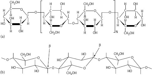
FIGURE 5.18 (a) Chemical structure of cellulose: Depiction 1. (b) Chemical structure of cellulose: Depiction 2. β refers to carbon–oxygen bond.
While the chemical structure is understood, the cellulose fine structure architecture in wood layers has still not been unequivocally determined (despite years of study). What is known are the following details: Cellulose does not exhibit branching; the molecules are extended and mostly linear. The hydroxyl groups from one chain form hydrogen bonds with oxygen from the same or a different chain. [Hydrogen bonds are those where the hydrogen molecule is essentially “shared” by two different oxygen molecules.] This interaction imparts a degree of “firmness” to the cellulose structure and allows the formation of clusters called microfibrils; the latter in turn form bundles of parallel microfibrils and these larger structures are referred to as fibrils. Such fibrils (visible under the microscope) display different orientations in different layers of the wood. The most common naturally formed cellulose is referred to as “cellulose I” (of which two forms exist). X-ray diffraction studies have shown that crystalline imperfections do exist.
Cellulose can be swollen by some solvents; a distinction is made between intercrystalline swelling and intracrystalline swelling. The former results from the action of water on the fibers and leads to an increase in the cross-sectional area. Soaking of cellulose in water leads to hydrogen bond formation on the fiber surface. Removal of the water by drying/heating causes the bond strength to increase. This is the physicochemical basis for the conversion of cellulose to paper, hence allowing development of a strong sheet or fiber mesh. Conversion of the fibrils into insulating paper is performed by conventional processes employed in the paper industry and, as noted previously, this natural polymer is manufactured as a tape that is wrapped around the cable core. Therefore, there are butt spaces that overlap in the cable construction. The cellulose in tape form may be employed in various thicknesses (depending on the application) and the fluids employed may vary in nature (chemical structure) as well as molecular weight.
The fluid serves to impregnate the butt spaces and ensure absence of voids. The dielectric fluids themselves are composed of carbon and hydrogen ~CH2~ groups, much like polyethylene, but their molecular weights are very much lower, so these are liquids that exhibit varying degrees of viscosity. The dielectric fluids are essentially hydrocarbon in nature, but the specific fluids employed have changed over the years. This means that the chemical structure of the fluid employed has been changed (in contrast to the cellulose portion of the paper/fluid combination). Fluids employed have been pine oil, mineral oil, paraffin and naphthenic oils (all of which possess different organic chemical structures), and synthetic butenes (also referred to as polybutene or polyisobutylene). Different polybutene fluids may possess different degrees of branching, hence affecting viscosity. In addition, rosins obtained from trees have mixed composition. The goal of all the fluids is to impart low dielectric losses.
Clearly, the fluid technology for paper cable has varied significantly over the years. Despite the changes, the commonality is that the final fluid remains basically hydrocarbon in nature (even though some of the fluids may contain more polar ingredients than others, and they may possess different antioxidants). The fact is that each modification can be expected to lead to different responses under voltage-thermal stress upon aging (see Section 5.10.2), leading to different long-term aging effects. Polybutene fluids are in common use for present-day PILC cables.
From an insulation materials perspective, one of the most significant ways to understand the differences between the natural polymer cellulose and the synthetic polyolefins like XLPE or EPR is to compare their behavior upon aging. Aging-induced degradation and loss of property integrity of polyolefins are covered in Chapters 6 and 19. Paper/fluid systems are reviewed here.
Cellulose can be considered as a “polyhydric” alcohol. (A simple alcohol would be ethanol.) The oxygen bonds connecting the cyclic structures are referred to as “1,4-glycosidic” bonds (Figure 5.18). These are the regions where the cellulosic molecule is susceptible to cleavage on aging. Water presence can cause breaking of these bonds, leading to a reduction in DP and thus loss of physical, mechanical, and electrical properties (e.g., reduction in tear strength or tensile strength and increase in dissipation factor); water may enter the construction through cracks in the lead sheath that is present over the cable core. Once degradation starts, more water is generated as a result of the chemical degradation of the cellulose molecule. The process is accelerated by elevated temperature. High temperature in the absence of water can also induce such degradation but the temperatures required in that situation are very high.
This degradation mode is significantly different from polyolefins such as XLPE, where the presence of water and voltage stress induce water tree formation and oxidizes the main polymer chain, but does not lead to a significant reduction in molecular weight by chain cleavage.
Under combined thermal/voltage stress, the fluid may undergo degradation. The molecules may be attacked by electrons, leading to free radical formation (see Chapter 6). When this occurs, two events are possible: (a) the fluid molecules may undergo chain cleavage, such degradation leading to a decrease in molecular weight (and viscosity); or (b) the free radicals may combine and lead to an increase in molecular weight. If the latter occurs, the viscosity will increase. As this process continues, and molecular weight continues to increase, the higher viscosity liquid is converted to a wax. Therefore, for our purposes, a wax can be visualized to be a “high molecular weight solidified oil,” but not as high in molecular weight as polyethylene. Waxes are intermediate in molecular weight, between those of viscous liquids and those of polymers like polyethylene. It is not uncommon to find wax upon autopsy of failed paper/fluid cables.
5.10.2.3 Paper–Fluid Combination
The degradation of the cellulose and the fluid/wax can occur simultaneously, and it is also possible for free radicals to attack the cellulose also and for synergistic effects to occur. These phenomena render attempts to isolate mechanisms of degradation very difficult on a molecular level. However, on a larger (macro) scale, another effect is very significant regarding the mechanism of degradation involving both components.
As paper-insulated cables age under load cycling and voltage stress, the fluid migrates into and out of the tape butt space regions as the temperature changes. Such migration can lead to voids developing as the fluid migrates. Voids are regions where the fluid is absent and air is present, and therefore are regions susceptible to partial discharges (see Chapter 6), which causes degradation. However, the fluid migration back into the butt space as a result of the load cycling process can render void presence as a transitory phenomenon. If the voids are large enough, even if temporary, they could lead to reliability issues upon continued aging.
The change in the nature of the fluid on aging, as described previously, can influence the migration of the fluid; if the fluid viscosity increases on aging, the ability to migrate under thermal load cycling becomes slower and more difficult. If wax develops, migration can be hindered even further, as waxes can restrict or prevent oil flow during load cycling, allowing detrimental microvoids to remain longer in butt spaces.
It is also possible that (some of) the wax may dissolve in the liquid portion of the fluid that did not degrade, hence increasing the viscosity. Also, wax that exists in the solid state at ambient temperature may soften and melt under high load cycling temperatures. Therefore, what is observed as a wax during an autopsy (always performed after the cable has cooled) may have been a viscous liquid during operating conditions. Another possible consideration is the potential role of water, if present, in displacing the fluid or wax.
This situation is obviously quite complex, and all these factors influence what happens in the butt space region of the paper tape–fluid insulation.
It is clear that paper-insulated cables are more complex than are their synthetic polyolefins counterparts; these issues do not exist for extruded solid dielectric cables. Both the fluid and the cellulose may degrade.
The fact is, however, that paper-insulated cables have an excellent history of reliability, and this is primarily attributed to the presence of an outer metallic lead sheath on these cables which prevents the incursion of air or water as long as the sheath retains its integrity.
A variety of tests are often employed to assess the state of the degraded paper-based cable as a result of aging. Some of these tests are noted here, as examples.
Moisture in tapes: As the paper portion of the cable degrades, moisture is evolved and it may be retained in the tapes. Measurement provides a qualitative indication of degradation.
DP: As noted above, the cellulose chain cleaves on aging and the DP is reduced. The technology involves dissolving the cellulose in a solvent and measuring the viscosity of the solution. Various methods have been applied over the years as cellulose is not easily dissolved and care in interpretation is required, as it has been reported that some measurement methods have caused depolymerization [32].
Fold endurance: Folding endurance represents the ability of paper to withstand multiple folds before it breaks. It is defined as the number of double folds that a strip of specific width and length can withstand under a specified load until breaking occurs. Folding endurance is useful in measuring the deterioration of paper upon aging. Long and flexible fibers provide high folding endurance.
Tensile strength: Tensile strength is a measure of the force required to produce a rupture in a strip and can be measured in the machine and cross machine directions. Tensile strength is indicative of fiber strength, bonding, and length. It can be measured when the paper is either dry or wet; both may drop on aging, the latter more. The wet tensile strength is less than the dry tensile strength.
Dissipation factor of fluid: As the oil degrades, it becomes more polar and the losses increase (see Chapter 6). Also, any evolved moisture that is “held” by the fluid will influence the dissipation factor. This is a common measurement applied to aged paper-insulated cables.
Additional tests on fluids: Diagnostic tests are available that can be applied to assess the specific chemical changes resulting from aging-induced degradation. One useful method is infrared analysis to determine chemical changes resulting from oxidation; degraded, oxidized regions absorb light in the infrared region to reveal their exact nature. Ultraviolet analysis is less common.
One further point is to be noted with reference to paper/fluid filled cables. It is possible that additives may be present that are not known and not addressed by industry specifications, but that may influence aging [33]. When this occurs, projections become difficult.
The discussion on aging reviews the significant differences between paper insulated cables and extruded cables with reference to: (1) construction, and (2) diagnostic testing after aging. One further point is notable to provide emphasis. Because of the significantly different (a) chemical structure of paper (cellulose molecules) as compared with extruded dielectric polymers, and (b) the paper cable construction itself (i.e., the presence of fluid to fill any voids that may develop in the butt gaps), it should not be surprising that each of these fundamentally different constructions will respond differently to external stresses. This is demonstrated by direct current (DC) high potential (HiPot) testing (see Chapter 18) that has traditionally been applied to installed aged paper cable systems to remove the “weak link” at the time of choosing (during the test). PILC cable of high integrity is not affected by application of DC when applied in accordance with industry guidelines, but aged PILC cable is induced to fail; the test can be employed to address cable integrity without harming the cable that has not degraded. The advantage is that the user can remove the weak link at the time of choosing, not during a crisis situation.
However, XLPE cables, due to the development of water trees, reduced dielectric strength and the tendency to “trap charges” (as well as the absence of any low molecular weight fluid to fill the voids), may be susceptible to harmful effects when subjected to DC HiPot testing. Much depends on the degree of degradation that the XLPE has undergone prior to performing the test. The test may remove the weak link as desired, but it may not. The problem is that the DC HiPot test may shorten the life of the XLPE insulated cable that has not failed during the test [34]. This does not happen with PILC cables.
The point here is that the response of electrical insulation materials to outside stresses in their application environment, both natural and imposed by the user, is intimately related to the physicochemical structure of the insulation material and the construction.
5.11 LOW VOLTAGE POLYMERIC INSULATION MATERIALS
The discussion to this point has focused primarily on polymeric materials employed for medium (and high) voltage insulation. Such materials must function under conditions where voltage stress is a significant parameter influencing reliability. For insulation materials operating at lower voltage stresses (e.g., 5 kV or less), thermal stress becomes a more significant factor in influencing reliability. Polymers employed in this voltage range include polyethylene and XLPE, but a variety of elastomers beyond EPRs may also be employed. These elastomers are reviewed in this section (the polyolefins having been reviewed earlier). Like all rubbers employed for insulation, these polymeric insulation materials must be compounded with numerous ingredients (as described in Section 5.6 for EPR) and they must be cross-linked.
An advantage of compounding polymers for low voltage applications is that it is possible to incorporate additives that enable a variety of specific characteristics to be met; an example is flame retardancy. It is possible to incorporate additives into the polymer formulation that will render the insulation more resistant to burning, yet still meet the required electrical properties. This is because the electrical property requirements for low voltage cable insulation allows greater flexibility, as operating voltage stresses are lower. This capability leads to a variety of different industry specifications designed to meet specific needs. This capability applies to polyethylene and XLPE, as well as to the elastomers. Another characteristic of this class of materials is that they find application as either insulation or jackets.
Elastomeric materials in this category include Neoprene, Hypalon, SIR, chlorinated polyethylene (CPE), and also PVC. (The historical development of Neoprene and Hypalon is discussed in Chapter 1). Table 5.4 shows the chemical structure of these materials.
Neoprene: Neoprene is also referred to as chloroprene; it is an elastomer derived from polymerization of the monomer 2-chloro-1,3 butadiene (recall that polyethylene is derived from the monomer, ethylene). The chlorine in the polymer backbone imparts the property of flame resistance. Neoprene resembles natural rubber (see Section 5.1.6) in many respects; mechanical properties such as tensile strength, elongation tear, and abrasion resistance, deformation and flex cracking resistance, and retention of properties at low temperatures. It is useful over a wide practical temperature range (−55°C to 90°C) depending on the specific formulation used (there are a number of grades available). This insulation material also possesses heat, ozone, corona, weather, chemical, and oil resistance as well as flame resistance. This polymer is considered a “general purpose” elastomer and these characteristics make it useful for wire insulation and cable jackets.
TABLE 5.4
Chemical Structure of Low Voltage Polymer Insulation Materials
Polymers Plus Monomers of Neoprene/Hypalon |
Structure |
Neoprene (monomer) 2 chloro-1,3 butadiene |
|
Hypalon (monomer) Chlorosulfonated polyethylene |
|
Chlorinated Polyethylene (CPE) [depiction/chlorination is random] |
|
Polyvinyl Chloride (PVC) |
|
Silicone Polydimethyl Siloxane |
|
RTV Silicone Polymer n 200 to 1,000 |
|
Polyethylene |
|
Ethylene Propylene Copolymer (EPR) |
|
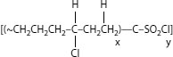
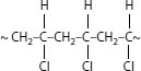


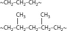
As with other elastomers, many additives are required to render Neoprene functional. The ingredients in a Neoprene formulation may vary widely; included are conventional fillers, an antioxidant, and a processing aid. Other components may include carbon black, paraffin, and stearic acid. A major difference between Neoprene grades for wire and cable applications is in the curing technology; a combination of magnesium and zinc oxide is employed and an accelerator such as ethylene-thiourea is employed to accelerate the curing process. Different accelerators lead to different properties [34].
Although the curing technology demonstrates significant differences between Neoprene and modern-day EPRs, the objectives of incorporating the other additives are similar. Antioxidants prevent oxidative degradation, fillers serve as reinforcing agents and improve mechanical properties such as toughness, as well as improve high temperature resistance, and carbon black serves to improve tear resistance, ozone and weather resistance.
Hypalon (CSPE): This polymer is an elastomer developed by DuPont (see Section 1.6) that also possesses chlorine in the backbone. There are various grades that impart not only flame resistance, but also resistance to ozone, heat, corrosive chemicals, and weathering, as well as provide superior thermal, mechanical, and electrical characteristics. It has been described as being capable of surviving abrasive, thermally and chemically abusive environments, while maintaining flexibility and inherent UV (sunlight) resistance. It is suitable for insulation and jacketing for low voltage applications.
Not only may the compositions vary, but also the curing systems; cross-linking is induced via different means (different functional portions of the polymer chain may be linked together.) State-of-the-art technology for processing (handling, mixing, and extruding) and various methods of cross-linking of Hypalon have been described [36]. It is noted therein that cross-linking can be induced via various means that include not only peroxides, but also through the highly reactive sulfonyl chloride sites.
To achieve the combination of desired properties, CSPE incorporates components in the formulations that have, more recently, become of concern. One reason is that the gases produced during combustion have varying levels of toxicity; a second reason is that CSPE often contains additives made from lead or lead compounds. Combining environmental issues with high manufacturing and labor costs, manufacturing has been restricted in some geographical areas. Fifty-nine years after first manufacturing CSPE, DuPont discontinued supplying the polymer. (Other overseas sources are available.)
Chlorinated polyethylene: By subjecting HMWPE to chlorination, the polyethylene is converted into an elastomer. (The larger chlorine replaces a portion of the smaller hydrogen in the polymer chain, and prevents chain alignment and crystallization). The modified polymer is flexible, has high tear strength, good chemical, and UV resistance, and possesses superior flame resistance as compared with the parent polyethylene. CPE is available as thermoplastic or thermoset; the technique for cross-linking CPE is the same as for other halogenated polymers. CPE has been suggested as a potential replacement for CSPE.
Polyvinyl chloride: Some basic information on PVC is in Section 5.8, where jackets are discussed. It is inherently a tough brittle polymer with poor heat stability, yet inherent flame resistance. The chlorine presence inhibits flammability (but at the expense of evolving toxic hydrogen chloride gas.) As with elastomers, PVC must be compounded with additives to render it useful. Interestingly, whereas elastomers require additives to impart toughness, PVC requires additives to induce softening. The major additive types that serve this role are called phthalate esters, which are high boiling stable liquids, and there are many (major ones being dioctyl phthalate and diisodecyl phthalate). The nature of this additive type affects low temperature properties, degree of softness, and stability on heating. Plasticizers also reduce the tensile strength (which is regained by use of other additives). Plasticizers are actually classified as two types, primary and secondary; the latter have limited compatibility and when used, the purpose is primarily to reduce cost.
Other additives include phosphates to impart flame resistance (the inherent flame resistance of PVC due to the chlorine is compromised to some extent by the phthalates), stearates to react with any hydrogen chloride gas that evolves on heating (lead, cadmium, barium, and zinc salts have also been used for this purpose), oils (lubricants), mineral fillers like clay or talc to provide “toughness,” carbon black, and sometimes organic phosphites have been used to prevent oxidation. Even other polymers have been incorporated to impart impact resistance. The chemistry and technology of PVC are massive and complex. In addition, due to the significant number and quantities of additives, the technology can be considered to be an art as well as a science.
Nevertheless, despite these complexities, studies with PVC have led to formulations successfully applied for numerous cable applications, and have been reliably and safely employed where the voltage stress and temperatures during lifetime usage are not excessive. Such PVC insulations provide: (a) good electrical insulating properties over temperature ranges defined in specifications; (b) ease of processing to meet the required specifications for end-use application; (c) long-life expectancy, as long as operated according to specifications; (d) durability; (e) resistance to ultraviolet light–induced degradation; (f) inherent flame resistance; (g) no need for cross-linking (hence reduced cost); (h) recyclability (as it is not cross-linked); and (i) cost-effectiveness.
Silicone rubbers: Unlike the low voltage polymers described above, silicone polymers are inorganic in nature (although they have also been defined as neither organic nor inorganic). The reason is that the polymers described so far are composed of carbon−carbon bonds in the backbone (organic) while silicones consist of silicon–oxygen or silicon–silicon) linkages. (A silicon-to-silicon linkage is called a silicone.)
Branches off the main chain in the silicone polymer may be methyl or larger molecules. These polymer chains are very flexible and maintain their flexibility over an extremely wide temperature range (−65°C to +315°C), which is a major incentive for its use. The exact useful temperature range depends on the specific nature of the SIR.
As with other elastomers, compounding with additives is required (the silicone itself may make up about 30% of the total composition). A typical compound may consist of the polymer, fillers, processing aids, other additives to facilitate resistance to heat aging, and the curing agent. The fillers have been defined as either reinforcing (which assists in improving properties) or extending (which serves no such role, but reduces cost). The resistance to oils, oxidation, UV (weathering), and abrasion are excellent, as are the electrical properties; however, tensile strength is not as good as that of the other polymers noted above. Nevertheless, the maintenance of properties of SIRs over the wide temperature range provides an advantage in that this property does not change significantly with temperature. Some SIRs swell in some solvents.
SIRs are manufactured by, first, reaction of metallic silicon (obtained by treating sand with carbon) with methyl chloride; then the products (mostly dimethyl dichlorosilane) condense in the presence of water to yield low molecular weight product consisting mostly of polymethyl siloxane. These products are then separated and polymerized further. Vinyl modified polymer is obtained by replacing a very small portion of the methyl chloride with vinyl chloride; the vinyl trimethoxy silane thus produced is much easier to polymerize. Cross-linking of the silicone polymer is performed by use of peroxides.
Room temperature vulcanizing silicone rubber (RTV): The SIRs described above possess nonreactive (e.g., methyl) end groups; hence, the cross-linking process being induced via peroxides. However, it is possible to manufacture low molecular weight silicones with reactive end groups. A typical reactive end group could be hydroxyl (–OH), meaning the polymer end group is a silanol (–Si–OH). This end group can react (link) with another silanol group, or with an alkoxy group (not a silanol), but in the latter case a catalyst is required. It can also react with water. There are two types of room-temperature vulcanizing silicones: RTV-1 is a one component system and cures in the presence of moisture (humidity). RTV-2 is a two-component system that cures when mixed and converts to a solid elastomer or a gel at room-temperature. The compositions are used for electrical insulation due to their dielectric properties. EAM polymers: Recent developments (compared in time with the polymers described previously) have led to polymer compositions composed of ethylene, methyl acrylate, and an alkenoic acid (e.g., ethoxyethyl acrylate) for low voltage applications. These are referred to as EAMs and are amorphous materials that possess good low temperature resistance combined with resistance to solvents, the extent depending on the ratio of ethylene to methyl acrylate in the chains). They can be readily modified to provide flame resistant compositions. The third monomer (1%–5% level) facilitates cross-linking by use of diamines [36].
This overview summary of various low voltage insulation polymeric material systems demonstrates both the similarities and differences of the different types. Similarities include: (a) the polymers employed are virtually all elastomeric in nature, (b) all require numerous additives to function effectively (some of which are identical), and (c) the ability to “tailor” properties to meet specific needs and specifications exists. Differences include: (a) possession of a wide range of physicochemical properties exhibiting different behavior over a broad temperature range, (b) significant differences in curing methodologies (which alters the properties and behavior of even a single polymer insulation type), and (c) the numerous variety of additives required to toughen some polymers yet soften another.
While the polymer technology in this area is quite mature, the additive technology remains dynamic. As an example, methodology is being sought to eliminate halogens from formulations while maintaining flame resistance (see Section 5.8). Numerous approaches have been explored to develop and apply low smoke, zero halogen or halogen free additives (LSZH or LSHF). These are intended to prevent flammability, smoke, and toxic by-product generation while still maintaining the ability to meet industry specification requirements (in an economical fashion). Conventional additives of this type are aluminum hydroxide and magnesium hydroxide, and their use with nanofillers (see the following paragraph) is an area of ongoing study.
Another dynamic area relates to inorganic fillers and particle size control. The use of fillers, (referred to throughout the discussions on elastomers) is essential to allow rubbery polymers to function effectively. A major role of fillers is to reinforce the polymer properties such as modulus and tensile strength.
Filler effectiveness can be characterized by: (1) the total surface area in contact with the polymer; (2) degree and nature of the interaction with the polymer (i.e., wetting capability); and (3) structure or geometry. Smaller particles clearly allow greater surface contact with the polymer, and typical conventional fillers would be in the millimicron range. Developments in the field of nanotechnology have allowed studies to be performed where fillers having particle sizes in the nanotechnolgy range (or three orders of magnitude smaller than conventional) are being studied. Materials reduced to the nanoscale have been shown to exhibit different properties compared with what they exhibit on a larger scale, thus enabling unique applications.
One attraction in this area of study is that nano-sized particles modify the electrical insulating properties of polymers. It appears that a significant increase in interfacial area contact (item 1 above) leads to far superior properties of the insulation employed for wire and cable applications. The reasons for this are under study. (It has been suggested that electronic properties of solids are altered in transition from micrometer to nanometer dimensions. With reference to this effect on fillers in polymers, considerations include greater electron scattering across the interfaces, increased electron trapping, reduced polymer free volume, or modified local conductivity.) Efforts to apply nanomaterials are proceeding independently of the basic research. Clearly, the factors noted in (2) and (3) above also play a role.
The role of conventional clay fillers in medium voltage EPRs is discussed in Section 5.6.2. Low voltage cables are also discussed in Chapter 9.
Insulation materials for low voltage (600 V) find application in secondary cables. The secondary network in urban underground systems is fed by primary feeders, the insulation materials of the latter being what has been discussed earlier. HMWPE, XLPE, and EPRs are employed in secondary networks, as are many of the polymeric insulations discussed in Section 5.11.1. These cables, due to their function, are expected to be able to serve reliably at elevated temperatures. Many are required to possess flame resistance. Materials that are inherently flame-resistant such as Hypalon, Neoprene, and PVC serve this role as low voltage jackets. Polyethylene, as discussed above, can be formulated with appropriate additives to possess this property. This applies to XLPE and EPR also. Application of LSZH insulation systems is applied in this direction. Where abrasion resistance is required, it is common to employ double layer; a tough outer jacket (like HDPE) over the more flexible inner insulation component. It is also possible to design secondary systems that are intended to “self-heal” if the outer jacket is penetrated. Insulation materials technology for secondary cables is very broad [38].
5.12 EXTRUDED CABLE REJUVENATION
5.12.1 INTRODUCTION TO THE CONCEPT
This section is concerned with technology that relates solely to aged extruded cables. As cables age over time, the utility is faced with the fact that such cables are eventually going to fail. Action can be taken to prolong life prior to actual failure. The process involves rejuvenating the cables so that they will remain “healthy” for a prolonged, extended period of time. This rejuvenation process involves injecting a silane monomer into the cable strands from where it diffuses into the insulation; it then polymerizes and also reacts with any remaining water during the rejuvenation process. The technology allows the now polymerized silane to fill any voids that may be present, and leads to an increase in the dielectric strength. This process is also applied after a failure occurs, but in that case the failed region must be removed and a splice installed prior to applying injection.
When cables begin to reach the point of exceeding their useful life, the utility is faced with the decision of whether to replace, repair, or rejuvenate. Cost is one factor, and replacement is often the most expensive path; disruption of service is another consideration. An additional consideration relates to the type of cable insulation involved. This section is concerned with the technical issues.
The history of the development of the rejuvenation process is of interest. The concept evolved from work that was done in the late 1970s–early1980s, after it was observed that many installed polyethylene-insulated cables were failing sooner than anticipated (due to water treeing). One industry response was to focus on XLPE as a HMWPE replacement; experimental evidence suggested that acetophenone, present in XLPE but not in HMWPE, was a tree-retardant additive. As seen in Figure 5.11, acetophenone is formed as a by-product from the decomposition of the cross-linking agent dicumyl peroxide. Hence, it was the cross-linking agent by-product (formed in-situ), not the XLPE itself, that imparted water tree resistance. However, acetophenone diffuses out of the cable over time and imparting of tree-retardant capability by this cross-linking agent by-product is not permanent. At a later time, industry efforts focused on developing permanent tree-retardant grade(s) of XLPE that were inherently superior to conventional XLPE (see Section 5.5).
Concurrent with these efforts to develop new superior cable insulation materials based on XLPE, efforts were also taken to improve the condition of already-installed older HMWPE and XLPE cable. Since it was clear that water presence was central to the premature loss-of-life upon aging, the first approach employed the concept of forcing the moisture from the buried cables by pumping compressed dry nitrogen gas through the interstitial spaces of the cable conductor strands, by employing a constant positive pressure. This approach was successfully applied as most early polyethylene cables possessed a multistrand core conductor, where there are longitudinal open air spaces between the conductor strands (interstices); this is the passageway used for sending gas through the cable. (With a solid conductor, it would not be possible to treat a cable in this manner.) The constant flow served to adequately remove moisture and at a later time, air was employed in place of nitrogen. Although cable life was extended via this methodology, the overall process had several limitations. Special terminations and fittings had to be crafted to allow proper entry and exit of gas flow; cable elbows and stress cones were modified accordingly, and special crimped connectors were required to allow the entering gas access to the stranded conductor. As the process depended on a constant flow of compressed gas, constant maintenance was required. If drying was interrupted, moisture could reenter the cable system.
The gas-based drying procedures were successful in preventing growth of water trees and in extending cable life. The observation that desiccation extended cable life was significant. However, the practical complexities involved were considered too great for ongoing application. As a result, the concept was extended by switching to the use of a compatible insulating liquid; acetophenone was chosen since, as noted above, at the time it had been demonstrated to impart tree resistance to XLPE-insulated cables. Tests on aged impregnated cables demonstrated that acetophenone incorporation led to the desired increase in alternating current (AC) breakdown strength. In practice, employing acetophenone did indeed force out the moisture and impurities in the cable as did compressed nitrogen. [Since acetophenone solidifies at about 20°C (58°F), the temperature control aspects of incorporating this chemical into a completed cable differ from the situation where it is formed in-situ during the cross-linking process.] Regardless, the use of the liquid in place of the gas was plagued by many of the same shortcomings as did the use of dry nitrogen. Acetophenone diffused out of the cable over time and constant maintenance was necessary to ensure constant flow of material, hence increasing costs.
An improved more practical approach that built upon this knowledge learned by working with dry nitrogen and acetophenone was developed in the 1980s. This process employed a special class of silicone materials (called alkyoxy silanes) to overcome the ongoing issue of diffusion of the fluid out of the cable. Here the small liquid molecule (which easily diffuses after being injected) undergoes a chemical reaction that simultaneously removes the water (a goal of the dry nitrogen or acetophenone treatment) and also increases in molecular weight (so the liquid cannot migrate out over time). The process was commercialized and first applied successfully by Tarpey and coworkers [39] at Orange and Rockland Utilities. It solved many of the prior issues and reduced the life extension concept to practice in an economical fashion.
Hence, the silicone fluid is injected into the stranded conductor of the cable, diffuses into the insulation, reacts with water and polymerizes, thereby undergoing an increase in molecular weight after impregnation. The higher molecular weight silicone component (called an oligomer) cannot migrate out the way the lower molecular weight acetophenone could. Since this process leads to permanent conversion of the liquid into a “gel” within the cable insulation, there is no need for ongoing application of external pressure. In addition, the curing process leads not only to filling of the voids, but also resists further moisture migration into the cable. Finally, this process leads to increased dielectric strength.
The conversion of the monomer into a polymer is analogous, in a general sense, to the conversion of ethylene into polyethylene (Section 5.2). In both cases, the low molecular weight component is induced to grow in length and form a polymer chain that possesses the desired properties. However, the analogy stops there, as there are very significant differences in the mechanism of the conversion process as well as the properties of the two polymer types; these differences are beyond the scope of this chapter, but it should be noted that the chain length of the polymerized silicone is relatively short compared to that of polyethylene and is referred to as an “oligomer.”
We will now review the chemistry of the rejuvenation process and then the practical application of the technology in the field.
Several silicone-based rejuvenation liquids may be employed. Phenyldimethyl siloxane (PMDMS) is the monomer that has been employed for many years, and is used as the basis for this discussion. This liquid has low initial viscosity (is therefore easy to inject), diffuses rapidly, reacts with water, and increases in chain length; rapid migration through the cable wall is a significant point. As the molecular weight increases, migration rate is reduced, and the oligomer remains locked in the region previously occupied by the water (i.e., the water tree). Figure 5.19 [40] shows the oligomerization process.
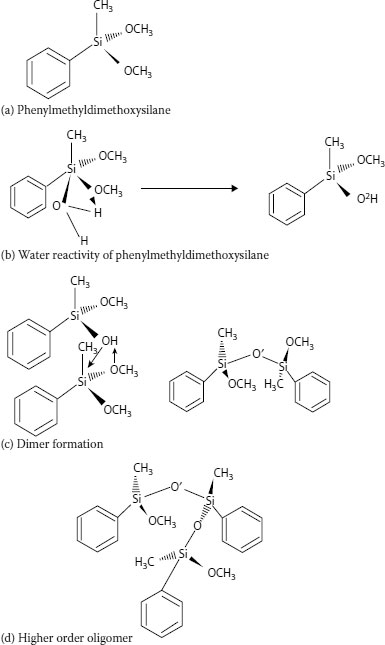
FIGURE 5.19 Polymerization of phenylmethyldimethoxy silane fluid. (The four parts show the reaction with water and depict chain growth.) (a) Phenylmethyldimethoxysilane. (b) Water reactivity of phenylmethyldimethoxysilane. (c) Dimer formation. (d) Higher order oligomer.
Figure 5.19a shows the chemical structure of PMDMS. The slightly polar methoxy functionality (−O−CH3) allows the molecule to be “attracted” toward the higher stress sites of the degraded polymer (water-treed region). The monomer then reacts with the water in the water tree.
Figure 5.19b shows the initial reaction where the polar hydroxyl functionality of the water (–OH) replaces the methoxy group.
Figure 5.19c shows the newly formed hydroxyl-containing monomer reacting with another PMDMS monomer. This leads to a higher molecular weight silicone, called a dimer, which can be considered to be the first step in the polymerization (oligomerization) process.
Figure 5.19d shows one possible following event; here the dimer (on the right side of Figure 5.19c), which now possesses reactive −O−CH3 functional groups, reacts with a monomer of the type shown in Figure 5.19b. The other methoxy groups shown in Figures 5.19c and d can also react (not shown).
It is also possible for the molecule produced in Figure 5.19b to react with water (before reacting with another PMDMS monomer), hence yielding a molecule with two hydroxyl groups; these reactions can occur concurrently (also not shown). Via this general process, the molecular weight increases.
Therefore, several technical issues for applying this technology all “move in the right direction.”
• The silicone liquid migrates into the cable core rapidly.
• The water is eliminated by chemical reaction with the silicone.
• The silicone monomer itself polymerizes (oligomerizes) and becomes a gellike structure.
• The polymerized silicone (oligomer) remains in the region that was originally holding water that harmed the polymer integrity.
• The new polymer resists water entry.
• The end result is increased dielectric strength and longer life.
Several points should be noted. (1) As indicated, PMDMS was used as the example; it is now common to employ this monomer in conjunction with other silicone monomers to enhance the functionality. (2) Newer technology has led to replacement of PMDMS by other silanes, referred to as dialkyl alkoxy silanes (an example being dimethyl dimethoxy silane). (3) A catalyst is required to initiate the polymerization process [41]. (4) It is possible to incorporate other chemical additives into the silicone monomer prior to impregnation [42].
5.12.3 IN-SERVICE PROCEDURE FOR CABLE REJUVENATION
This section provides an overview of the practical aspects involved in imparting improvements to the performance of installed aged extruded cables. Installation of new cables is covered in Chapter 12; here we are concerned with field procedures that are not related to the original installation, but that are relevant to successful implementation of the chemical reactions. For a discussion of the accessories described, the above chapters should be reviewed. Diagnostic procedures to assess the “state” of the cable that could be applied prior to impregnation are discussed in Chapter 18.
The following description, which clarifies the practical aspects of implementation, applies to procedures for URD cable; for feeder cable, the procedures differ slightly.
1. The cable is de-energized.
2. A diagnostic test (time domain reflectometry or TDR) is performed to determine the cable length and to ensure that the cable concentric neutrals are not corroded and are functioning satisfactorily.
3. Modified accessories are installed: injection elbows or live front injection adaptors are typically retrofit. These remain permanently on the cable (200 amp load break injection elbows are commercial available).
4. The cable may then be re-energized.
5. Flow and pressure tests are performed; nitrogen is injected at one end of the cable and outflow is measured at the other end. The cable is pressurized and flow is monitored. The purpose is to ensure there is good flow, no leaks, and to remove any water that may be in the strands. Splice location is also pinpointed; conventional splices will generally allow flow of fluid, but some premolded splices may require excavation or repair.
6. The cable is then treated (the fluid has been described in Section 5.12.2). A feed tank injects the fluid into the cable and a vacuum tank is placed at the collection end. The process typically takes place overnight.
7. The feed tank is left in place. The time is such as to allow an adequate amount of fluid to diffuse and penetrate into the insulation. Cable insulation wall thickness influences the requirement.
The process described is to ensure that the cable system (including splices and terminations) is suitable for impregnation, that proper and complete impregnation takes place, and that curing takes place when desired (not prematurely).
For further information, the references should be reviewed.
5.13 COMPARISON OF MEDIUM VOLTAGE INSULATING MATERIALS
Table 5.5 provides a general summary comparing the properties of various types of polymer insulation materials for cables. The significant differences between the natural polymer cellulose (paper) based materials and the synthetic polyolefin based materials (XLPE, TR-XLPE and EPR) are summarized for ease of review. This brief table is considered to be general and not definitive. For example, the EPR information provided is based on the general discussion noted in Section 5.6.1. There are caveats about EPRs regarding the composition, dielectric losses, and the general philosophy regarding how to achieve reliability, which affect the limited information caught in short phrases in the entries in the table. Hence, not all EPRs will readily fall into the attempted comparison sought therein. Care must be taken in seeking to compare different EPRs with each other (as well as to XLPE and TR-XLPE and paper systems). There are many different EPR formulations, and all do not necessarily respond in the same manner upon aging. The nature of the nonpolymeric additives, including fillers, plays a major role in influencing the properties as does the nature of the mixing process. Section 5.6.3 should be reviewed for internal EPR comparisons.
TABLE 5.5
Comparative General Properties of Insulation Materials in Medium Voltage Cables
XLPE/TR-XLPE |
EPR |
Paper/Cellulose-Fluid |
Synthetic polymer: solid dielectric |
Synthetic polymer: solid dielectric |
Natural polymer; tape construction plus natural or synthetic fluid |
Carbon/Hydrogen polymer |
Carbon/Hydrogen polymer |
Carbon/Hydrogen/Oxygen polymer |
Low losses |
Filler-induced higher losses |
Higher losses |
Semicrystalline |
Little to no crystallinity: amorphous |
Paper: crystalline fibrils fluid: amorphous |
Thermal expansion as temperature increases |
Slight thermal expansion as temperature increase |
Fluid: slight thermal expansion and migration through tapes |
Cross-linked polymer structure |
Cross-linked polymer structure |
Not cross-linked |
Water plus voltage stress induces water trees TR-XLPE is water tree resistant |
Water plus voltage stress induces water trees; lesser extent than XLPE |
Water cleaves C–O linkages. No water trees |
Dry aging leads eventually to electric trees |
Dry aging leads eventually to electric trees |
Dry aging leads eventually to chain cleavage |
Low permittivity |
Slightly higher permittivity |
Highest permittivity |
Cable less flexible the EPR |
Cable more flexible than XLPE or TR-XLPE |
Not applicable due to Pb sheath |
Reduced weight vs. PILC |
Reduced weight vs. PILC |
Greater weight vs. extruded |
Easier to repair faults |
Easier to repair faults |
More difficult to repair faults vs. extruded |
Easier to apply accessories |
Easier to apply accessories |
More complex to apply accessories |
Surges, DC HiPot testing may harm aged cable and shorten life, if failure does not occur at time the stress occurs |
Surges, DC HiPot testing may harm aged cable and shortened life, if failure does not occur at time the stress occurs |
No evidence of shortened life by stress described |
The same caveat applies to paper-insulated cables that employ various fluids and a lead sheath.
In comparing polymeric insulation materials, it is common to describe crosslinked (thermoset) polymers as not being reprocessable, reformable, or recyclable. This certainly is true for rigid or “glassy” polymers, one example being epoxies (not employed as cable insulation); once they are cross-linked they cannot be reprocessed and reused, as they cannot be remelted. On the other hand, conventional polyethylene, being thermoplastic, can be remelted (and hence recycled, reprocessed, and reformed into another product, cable or otherwise).
TABLE 5.6
Classification of Polymer Types Regarding Refabrication
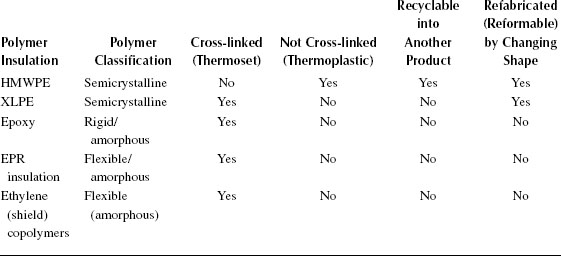
Some ambiguity exists in the classification of XLPE. Since it is cross-linked, it cannot be recycled into another product, but it can (and is) be reformed (an option not possible with an epoxy). The reason is due to the semicrystalline nature of the XLPE; the crystalline regions can be remelted at elevated temperatures, even though the cross-linked regions cannot be recycled. Physical modification and cooling then allow the XLPE to assume a reformed shape. Thus, the semicrystalline polymer, even though being cross-linked, can be refabricated. (This has been discussed in the latter portion of Section 5.4.3.) These distinctions are summarized in Table 5.6.
1. Kressner, T. O., 1969, “Polyolefin Plastics,” Van Nostrand Reinhold Publ. Co.
2. Morton, M. (ed.), 1973, “Rubber Technology,” Second Edition, Van Nostrand Reinhold Publ. Co.
3. Sengupta, S., Person, T. and Caronia, P., June 2010, “A New Generation of Tree Retardant Cross-linked Polyethylene (TR-XLPE),” Conference Record of the 2010 IEEE International Symposium on Electrical Insulation, pp. 1–6, San Diego, CA.
4. Raff, R. and Doak, K., 1965, “Crystalline Olefin Polymers,” Vol. 1 and 2, Interscience Publishers.
5. Billmeyer. F., 1971, “Textbook of Polymer Science,” Chapter 3, pp. 84–90, Wiley Interscience Publisher.
6. Miller, M. L., 1968, “The Structure of Polymers,” Chapter 10, p. 494, Van Nostrand Reinhold Publishing Co.
7. Vasile, C., 2000, “Handbook of Polyolefins (Plastic Engineering),” Second Edition, Marcel Dekker, Inc.
8. Charlesby, A. 1960, “Atomic Radiation and Polymers” Polymers,” Pergamon Press; Chapiro, A., 1962, “Radiation Chemistry of Polymeric Systems,” Interscience Publisher; Odian, G. and Bernstein, B. S., 1964, “Radiation Cross-linking of Polymers via Polyfunctional Monomers,” Journal of Polymer Science, Vol. A2, p. 2835.
9. Pauling, L., 1953, “The Nature of the Chemical Bond,” Cornell University Press (); Flory, P. J., 1953,“Principals of Polymer Chemistry,” Cornell University Press.
10. Winspear, W. G. (ed.) “Vanderbilt Rubber Handbook,” Chapter 1, Martens, S.C., “Chemically Crosslinked Polyethylene,” R.T. Vanderbilt Company, pp. 226–227; also, 1983, “Hercules Peroxides,” Hercules Chemical Company Bulletins ORC, pp. 101E, 104E, 201–208.
11. Bernstein, B. S., Odian, G., Binder, S. and Benderly, A., 1966, “Physical and Electrical Properties of Polyethylene Radiation Cross-linked by Polyfunctional Monomers,” Journal of Applied Polymer Science, Vol. 10, p. 143.
12. Gross, L., October 1988, “Polyethylene Silane Co-polymers as New Low Voltage Insulation Systems” Paper Presented at Wire Association International Convention, Toronto Canada; see also, Wire Journal International, November 1988, pp. 59–66: See also, Caronia, P., April 2005, “Overview of Polyethylene used in 600V Underground Secondary Cables,” Paper Presented at Spring 2005 IEEE Insulated Conductors Committee Meeting, pp. 791–806, St.Petersburg, FL.
13. Conley, R. T., 1970, “Thermal Stability of Polymers,” Chapter 6, Hansen, R. H., “Thermal and Oxidative Degradation of Polyethylene, Polypropylene and Related Olefin Polymers,” Marcel Dekker, Inc.
14. Ezrin, M., Seymour, D., Katz, C., Dima, A. and Bernstein, B. S., June 1986, “Thermal Response of Cable Insulation, Shield and Jacket Materials Aged at 130C and Above,” Proceedings of IEEE International Symposium on Electrical Insulation, Washington DC, p. 46; also, Katz, C., Dima, A., Zidon, A., Ezrin, M. Zengel, W. and Bernstein, B. S., May 1984, “Emergency Overload Characteristics of Extruded Dielectric Cables Operating at 130C and Above,” Proceedings of IEEE T&D Conference, Kansas City, MO.
15. Jow, J. and Mendelsohn, A., Spring 1999, “Tree Retardant XLPE Technology Review,” Proceedings of IEEE Insulated Conductors Committee Meeting, Charlotte, NC.
16. Brown, M., January–February 1994, “Compounding Ethylene Propylene Polymers for Electrical Applications,” IEEE Electrical Insulation Magazine, Vol. 10 (No. 1), pp. 16–22.
17. Borzenski, F. J. and Valsamis, L. N., 1 July 2002, “Optimizing Mixing in the Farrell Banbury Mixer” Rubber World.
18. Kalyon, D. M., “Mixing in Continuous Processes,” Encyclopedia of Fluid Mechanics, Chapter 28, http://www.hfmi.stevens-tech.edu/publications/174.PDF; also, Buss brochure “Buss Kneader Technology for Cable Compounds,” www.busscorp.com.
19. Bartnikas, R. (ed.), 2000, “Power and Communications Cables,” (a) Chapter 9, p. 406, (b) Chapter 1, p. 35, McGraw Hill Publ. Co.
20. Qi, X. and Boggs, S., May–June 2006, “Thermal and Mechanical Properties of EPR and XLPE Cable Compounds,” IEEE Electrical Insulation Magazine, Vol. 22 (No. 3), pp. 19–24.
21. Banker, W. and Katz. C., 2000, “Update on Field Monitoring and Laboratory Testing of EP & TR-XLPE Distribution Cables,” Proceedings of IEEE/PES Insulated Conductors Committee, Fall Meeting, St. Petersburg, FL, pp. 119–124; also, Katz, C., Fryszczyn, B., Bernstein, B. S., Regan, A. M. and Banker, W., July 1999, “Field monitoring of Parameters and Testing or EP and TR-XLPE Distribution Cables,” IEEE Transactions on Power Delivery, Vol. 14 (No. 3), pp. 679–684; also, EPRI Report 1009017 “In-Service Performance Evaluation of Underground Distribution Cables,” 2003.
22. Smith. R., March 2009, “Kerite Review of Cable Submergence,” Paper Presented at Nuclear Regulatory Commission Cable Workshop, Rockville, MD.
23. Eichhorn, R. M., December 1981, “A critical Comparison of XLPE and EPR for use as Electrical Insulation on Underground Power Cables,” IEEE Transactions on Electrical Insulation, Vol. EI–16 (No. 6), pp. 469–482.
24. Han, S. J., Mendelsohn, A. and Ramachandran, R., 2006, “Overview of Semiconductive Shield Technology in Power Distribution Cables,” Proceedings of IEEE Power and Energy Society, Transmission and Distribution Conference, Paper TD2005-000590.
25. Forester, E. O. and Spenadel, L., January 1973, “Black-Filled EP Rubbers,” Rubber Age, pp. 39–45.
26. Dannenberg, E. M., 1979, “Carbon Black,” Kirk Othmer Encyclopedia of Chemical Technology, Vol. 4, Third Edition, John Wiley and sons.
27. Smith, R. and Hu, H., April 1991, “An Introduction to the Designs and Philosophies of the Kerite Company,” Paper Presented at the AEIC Cable Engineering Section, Charleston, SC.
28. Stenger, R. J., 9 April 1985, “Filling materials For Electrical Cable,” U.S Patent 4,509,821.
29. Clark, G. L. and Hawley, G. S., 1957, “The Encyclopedia of Chemistry,” pp. 696–697.
30. Dunsheath, P., 1929, “High Voltage Cables,” Sir Isaac Pitman and Sons Ltd.
31. Brown, T. L., LeMay, Jr., H. E. and Bursten, B. E., 1994, “Chemistry the Central Science,” Prentice Hall Publ Co., Englewood Cliffs, New Jersey, Sixth Edition, p. 990.
32. Kaminska, E., 1996, “Determination of Degree of Polymerization of Cellulose in Ligneous Papers,” Materials Research Society Symposium Proceedings Fall 1996, Vol. 462; Alexander, W. J. and Mitchell, R. L., December 1949, “Rapid Measurement of Cellulose Viscosity by Nitration Methods,” Analytical Chemistry, Vol. 21 (No. 12), pp. 1497–1500; Lewin, M., (ed.), 2007, “Handbook of Fiber Chemistry,” pp. 429, 488–489, CRC Press.
33. El-Sulaimin, A. A. and Uershi, M. I., September 1996, “Effect of Additives on Performance of Cable Oil and Kraft Paper Oil Composite,” Journal of Electric Power Components and Systems, Vol. 24 (No. 6), pp. 597–608.
34. Srinivas, N. and Bernstein, B. S., 1991, “Effect of DC Testing on Aged XLPE-Insulated Cables with Splices,” Proceedings of JICABLE 91, Paper B31, Versailles, France.
35. Allinger, G., and Sjothun, L. J. (eds), 1964, “Vulcanization of Elastomers,” Stevenson, A.C., Chapter 8, “Neoprene, Hypalon and Fluoroelastomers,” pp. 265–285, Reinhold Publ. Co.
36. Klindenger, R. C., 2008, “Handbook of Specialty Elastomers,” Chapter 9,“Chlorsulfonated Polyethylene and Alkylated Chlorosulfonated Polyethylene,” CRC Press; also, DuPont Dow Brochure H-68574-01“Hypalon Chlorosulfonated Polyethylene,” November 1998.
37. White, J. R., 2001, “Rubber Technology Handbook,” pp. 66–67, Smithers Rapra Publ. Co.
38. Doherty, F. and Bernstein B. S., “Self Sealing Cables: State-of-the-Art,” IEEE Insulated Conductors Committee Meeting, Paper A-9, pp. 206–219; Szanislo, S., April 2005, “A Review of Secondary Cable Basics,” Paper presented at ICC Education Forum, pp. 725–910, St. Petersburg, FL.
39. Nannery, P., Tarpey, J., Lacanere, J., Meyer, D. and Bertini, G., October 1989, “Extending the Service Life of 15kV Polyethylene URD Cable Using Silicone Liquid,” IEEE Transactions on Power Delivery, Vol. 4 (No. 4), pp. 1991–1996.
40. Stagi, R. and Chatterton, W., June 2007, “Cable Rejuvenation; Past, Present and Future,” Proceedings JICABLE 2007, Paper C.7.2.14, pp. 858–861, Versailles, France.
41. Chatterton, W. J., October 2008, “The Chemistry of Cable Rejuvenation,” Paper Presented at EUCI Conference, Phoenix, Arizona.
42. Busby, D. and Bertini, G., October 2010, “Cable Rejuvenation Mechanisms: An Update,” Paper Presented at CIGRE Canada Conference on Power Systems, Vancouver, Canada.
POLYETHYLENE CHAIN MOTION AT VERY LOW TEMPERATURES |
At very low temperatures (−100°C to 0°C), brittleness becomes an issue for polyethylene (and EPR also) and cracking can occur. Prior studies of the observed random motion of the polyethylene chains at very low temperatures have been divided into three categories, traditionally referred to as alpha, beta, and gamma. Polyethylene’s “simple” −CH2− repeating unit can behave in a far from simple manner when seeking to understand structure–property relationships.
The first of the three categories has been believed to be due to crystallite chain twisting between amorphous phases; the second is related to chain motion at the boundaries of the crystalline–amorphous interface, and the third is believed to be due to motion of chains of specific lengths. These phenomena influence properties at low temperatures (e.g., low temperature brittleness). These details of the fine molecular structure are noted here to emphasize just how complex is the nature of seemingly simple polyethylene molecule; XLPE, TR-XLPE, and EP are even more complex.
SINGLE SITE CATALYST POLYMERIZATION |
The advent of newer single site catalysts for producing polyethylenes ultimately raised an older subject to higher visibility. In order for a polyethylene to be adequately extruded for application in cables, it must be melted in the extruder at elevated temperatures and be pushed through a die. A smooth surface is achieved by controlling the extrusion rate. As the extrusion rate increases, potential problems may arise: these are called “sharkskin” and at higher rates “melt fracture.” “Sharkskin” refers to a rough surface with repeated patterns of ridges. At conventional extrusion rates, the insulation surface is smooth as it emerges from the extrusion die; at higher rates, flow instability can occur. This phenomenon is related to molecular weight, molecular weight distribution, and surface interfacial phenomena. This is not a problem with polyethylenes produced by the conventional high pressure process, as it is moderated by their relatively wide molecular weight distributions at conventional extrusion rates. Therefore, having a broad molecular weight distribution is not necessarily “bad” from a processing perspective. However, polyethylenes with narrow molecular weight distributions have been more prone to development of “sharkskin,” even at relatively moderate extrusion speeds. Research is ongoing to better understand the causes and mitigate the problem. “Melt fracture” only becomes an area for consideration at significantly higher than conventional extrusion rates.
For the record, the newer metallocene catalysts are metal complexes possessing cyclopentadienyl (Cp) or substituted Cp groups. The conventional Ziegler Natta catalysts are typically based on titanium and chlorine. The former technology is used to manufacture LLDPE, used as cable jackets.
Despite the practical processing difficulties, the single site catalyst approach offers much promise, and studies are ongoing. Information provided by materials suppliers suggests the following potential advantages in applying advanced single site catalyst technology:
• Variety of comonomer choices
• Controlled molecular weight distributions
• Better control of crystallinity
• Controlled long chain branching
• Better balance of properties
• Improved physical properties
• Improved ease of installation (due to greater flexibility)
• Improved filled systems
• Superior cleanliness due to better catalyst efficiencies