
CONTENTS
10.2 Manufacturer Organizations
10.2.1 Insulated Cable Engineers Association
10.2.2 National Electrical Manufacturers Association
10.3.1 Association of Edison Illuminating Companies
10.3.2 Rural Utilities Service (RUS) [Previously REA]
10.4.1 American National Standards Institute (ANSI)
10.4.2 American Society for Testing and Materials (ASTM)
10.4.3 Canadian Standards Association (CSA)
10.4.4 International Electrotechnical Commission (IEC)
10.4.5 National Electrical Code (NEC)
10.4.6 Underwriters Laboratories (UL)
10.5 Typical Features of Standards and Specifications
10.5.3.2 Insulation Thickness and Test Voltages
10.5.4 Extruded Insulation Shields
10.5.4.3 Insulation Shield Thickness
10.5.5.1 Concentric Neutral Cables
Standards and specifications for power, control, signal, instrumentation, and communication cables have been prepared in North America by various industry organizations since the early part of the twentieth century. These are commonly referenced in user specifications and supplemented by the user to include specifics required by the user. Electrical cables are manufactured to these requirements, depending on the application of the particular installation.
The power cables that are covered by these standards and specifications can be classified under three major categories:
• Low voltage cables rated up to 2,000 volts
• Medium voltage cables rated 2,001 to 46,000 volts
• High voltage cables rated 69,000 volts to 765,000 volts
The most widely used documents in North America are those issued by the Aluminum Association (AA), American National Standards Institute (ANSI), American Society for Testing and Materials (ASTM), Canadian Standards Association (CSA), Insulated Cable Engineers Association (ICEA) in conjunction with the National Electrical Manufacturers Association (NEMA), the Association of Edison Illuminating Companies (AEIC), the Rural Utilities Service (RUS), and Underwriter’s Laboratories (UL) in conjunction with the National Electrical Code (NEC). These organizations may loosely be categorized into:
1. Manufacturer organizations
2. User organizations
3. Consensus organizations
10.2 MANUFACTURER ORGANIZATIONS
10.2.1 INSULATED CABLE ENGINEERS ASSOCIATION
This group was formerly known as IPCEA. They removed the “Power” from their name to more accurately describe a broader scope of activities. Divisions in ICEA include:
• The Energy Cables Division comprises three Sections: (a) the Power Cable Section, (b) the Control & Instrumentation Cable Section, and (c) the Portable Cable Section.
• The Communication Cables Division comprises two Sections: (a) the Copper Section and (b) the Optical Fiber Section.
Membership is made up of technical employees, who are sponsored by over 30 of North America’s leading cable manufacturers. They develop standards, guides, and committee reports on all aspects of insulated cable design, materials, and applications. They work with other organizations toward the development of joint standards. Many of their standards are subject to the approval of NEMA and are published as joint ICEA/NEMA standards. Others are approved as an American National Standard by ANSI.
These standards encompass the entire cable: conductor, shields, insulation, jackets, testing, etc. The only possible omission is packaging. This is considered to be an area that is not allowed by US law.
Both ICEA and NEMA standards may be purchased from Global Engineering Documents, 15 Inverness Way East, Englewood, CO 80112, USA.
10.2.2 NATIONAL ELECTRICAL MANUFACTURERS ASSOCIATION
NEMA is the trade association of choice for the electrical manufacturing industry. NEMA members are from cable manufacturing organizations and generally they are from the commercial side of those companies.
The AA tends to impact cable standards and specifications by representation on organizations engaged in these activities. The association has taken the lead in specifying ingredient and impurity levels in aluminum alloys used for conductors, and until recently had published code words for many bare, covered, and insulated aluminum wires and cables. These code words are widely used to specify and purchase the wires and cables coded. The ASTM has now assumed such responsibility for the ones pertaining to bare conductors and the ICEA for the rest.
10.3.1 ASSOCIATION OF EDISON ILLUMINATING COMPANIES
Since November 1, 1924, power cable specifications have been written by the Cable Engineering Committee of the AEIC, a group of investor-owned and municipal utility company engineers. They also prepare guides that pertain to power cables.
Their first specifications were written for paper-insulated cables for mediumvoltage applications. Presently, their specifications cover all forms of laminated cables from 1 to 765 kV such as paper-insulated metallic-sheathed, self-contained liquid-filled and high-pressure pipe-type cables. These specifications include conductors, insulations, sheaths, shields, jackets, and testing requirements.
AEIC also prepares specifications for extruded dielectric cables from 5 to 345 kV that build upon the ICEA standards (hence also on the applicable ASTM requirements). AEIC uses the ICEA standards for such items as conductors, shields, jackets, and testing requirements. A unique feature of AEIC’s past extruded cable specifications is that they require a qualification test to be performed on a sample of cable that represents the cable to be manufactured. This has now found its way into the ICEA standards for utility cables [14,16].
Another feature of AEIC’s specifications for extruded cables is that a checklist of the available options is presented. This can be useful for those users that are in the process of developing a user specification for themselves.
AEIC documents are available from AEIC, 600 N. 18th St., P. O. Box 2641, Birmingham, Alabama 35291-0992, USA.
10.3.2 RURAL UTILITIES SERVICE (RUS) [PREVIOUSLY REA]
This is also a user group of the US Department of Agriculture. Their Electric Program lists borrowers by state; provides guide specifications; building plans and drawings; electrical design and construction policies and procedures; electrical standards for materials and construction for use by the Rural Electric Cooperatives of the US.
10.4.1 AMERICAN NATIONAL STANDARDS INSTITUTE (ANSI)
ANSI membership and polling lists involve all interested parties. Thus, ANSI standards are consensus standards. ANSI does not develop standards, but rather elevates standards developed by others to a consensus level by a voting procedure.
10.4.2 AMERICAN SOCIETY FOR TESTING AND MATERIALS (ASTM)
ASTM International, formerly known as the American Society for Testing and Materials (ASTM), is a globally recognized leader in the development and delivery of international voluntary consensus standards. Membership includes raw material suppliers, manufacturers, users, and general interest groups. As such, ASTM is a consensus organization. ASTM is organized for “the development of standards on characteristics and performance of materials, products, systems and services.”
10.4.3 CANADIAN STANDARDS ASSOCIATION (CSA)
The CSA is a not-for-profit membership-based association serving business, industry, government, and consumers in Canada and the global marketplace. It functions as a neutral third party, providing a structure and a forum for developing standards.
Their committees are created using a “balanced matrix” approach, which considers the views of all participants and develops the details of the standard by a consensus process. Substantial agreement among committee members, rather than a simple majority of votes, is necessary. When a draft standard has been agreed upon, it is submitted for public review, and amended if necessary.
10.4.4 INTERNATIONAL ELECTROTECHNICAL COMMISSION (IEC)
The IEC is the world’s leading organization that prepares and publishes International Standards for all electrical, electronic, and related technologies—collectively known as “electrotechnology.” Each National Committee of the IEC handles the participation of experts from its country. Technical Committees prepare technical documents on specific subjects within their respective scopes, which are then submitted to the full member National Committees (IEC’s members) for voting with a view to their approval as international standards.
10.4.5 NATIONAL ELECTRICAL CODE (NEC)
The NEC is written by a number of panels, each addressing specific sections of the NEC. Membership of the panels is carefully controlled to avoid having any single interest group gain control over the panel. The NEC covers wire, cables, and wiring methods in facilities frequented by the general public. The only specific exemption is facilities under the control of electric utilities that are not facilities used to host the general public such as customer service areas. The NEC is adopted by ANSI and is adopted in whole or part (or not at all) by governmental agencies.
10.4.6 UNDERWRITERS LABORATORIES (UL)
UL has published a wide range of standards covering wires and cables specified by and for use in accordance with the NEC. UL both lists and labels acceptable designs and acts as a third party inspector by having UL inspectors visit the manufacturer’s facilities to conduct tests to verify that the manufacturer is meeting the standard for the product(s).
10.5 TYPICAL FEATURES OF STANDARDS AND SPECIFICATIONS
CSA, ICEA, and UL power cable standards include both copper and aluminum conductors, which are covered by individual ASTM standards. Since in most instances direct current (DC) resistance is the governing factor for confirming conductor size, these standards specify a maximum resistance for each American Wire Gauge (AWG) and thousands of circular mils (kcmil) size. ICEA conductor diameters are required to meet a nominal diameter ±2%.
ASTM standards for concentric-lay-stranded conductors give the manufacturer the option of “compressing” Class B and C conductors. This means that the overall diameter of such a conductor may be a maximum of 3% lower than that of a “concentric” conductor. The need and advantages for such compression were presented in Chapter 3. Thus, even if “concentric” stranding is requested, the manufacturer has the option of providing “compressed” strand.
An important decision that must be made involves the temper of the metal. This option should be based on such factors as the anticipated pulling force, required flexibility, and also on the cost.
The harder the temper, the greater will be the pulling force that can be applied to the conductor during installation. A half-hard aluminum conductor will withstand less force than a three-quarter or full-hard conductor. On the other hand, any increase in temper results in a conductor that is harder to bend and is thus less flexible. However, this additional bending force of the bare conductor may be negligible when compared with that of the finished cable. When the wires are drawn for the conductor stranding process, the metal is work hardened and the temper increases. Annealing either during the wire drawing process or after the conductor has been stranded will decrease the temper, but this takes energy so there is an increase in the cost of an annealed conductor. All of these points need to be weighed before a decision is reached.
Cable manufacturers have the capability of indent printing the center strand of a seven-strand or greater Class B or C conductor. If requested at the time of the inquiry, they can also print the year of manufacture and their name at regular intervals on this center strand. This provides a lasting identification of the manufacturer and the year.
Another consideration is to block, or fill, the strands of a Class B conductor with a compound that eliminates almost all the air from the interstices. This prevents the accumulation of moisture in the air space as well as longitudinal moisture movement along the cable. The elimination of water in the strand reduces the treeing concerns and increases the life of cables in accelerated treeing tests. ICEA standards contain a test for the effectiveness of this “water blocking” [12,14,16].
Another method of keeping water from entering (or leaving) the strand is to install a metal barrier in the semiconducting strand shielding. The layer is a “sandwich” of the semiconducting material with a lead or aluminum overlapped tape in the center.
Conductor shielding (either a semiconducting or nonconducting stress control layer) is required for cables rated 2,000 volts and higher by these standards. Conductor shielding normally consists of an extruded semiconducting layer applied between the conductor and the insulation. For this layer to function properly, it shall be easily removable from the conductor and the outer surface of the extruded shield should be firmly bonded to the overlying insulation to ensure that there are no air voids between the conducting layer and the insulation.
This extruded semiconducting material is made from a polymer that will ensure compatibility with the insulation and a strong bond at the interface. Its conducting properties are obtained by adding particles of special carbon black. The present requirement for the maximum resistivity of this layer is 1,000 ohm-meter at the maximum normal operating temperature and emergency operating temperature. Industry standards require this material to pass a longtime stability test for resistivity at rated emergency overload temperature of the cable. Accelerated tests have shown that the cleanliness of the material can significantly affect the life of the cable when it is in a wet environment. Compounds that are demonstrably smoother and/or cleaner than conventional compounds can improve the life of a cable in an accelerated water treeing test significantly.
The nonconducting rather than semiconducting stress control layer that may be used has properties that are best described as having a high dielectric constant (high K) material. This means that it acts like a rather poor conductor and produces a very low voltage drop between the conductor and the insulation. It does provide the stress control that is needed for smoothing out the conductor surface.
In some applications, a semiconducting tape may be applied over the conductor and under the semiconducting layer. This functions as a binder and is sometimes used for larger conductors.
If a semiconducting conductor stress control layer is used, the resistivity is measured between two painted silver electrodes placed at least 2 inches apart on the conductor stress control layer. If greater accuracy is desired, current electrodes may be placed 1 inch beyond each potential electrode.
The resistance shall be measured between the two potential electrodes. The power of the test circuit shall not exceed 100 milliwatts.
The volume resistivity is then calculated from the following equation:
(10.1) |
where
ρ = volume resistivity in ohm-meters
R = measured resistance in ohms
D = diameter over conductor stress control layer in inches
d = diameter over conductor in inches
L = distance between electrodes in inches
Cross-linked polyethylene (XLPE) (including tree retardant XLPE [TR-XLPE]) and ethylene propylene rubber (EPR) are the dominant materials presently used as the insulation for medium voltage cables.
AEIC prepares specifications for extruded dielectric cables from 5 to 345 kV [1] that covers both cross-linked (thermosetting) polyethylene and ethylene–propylene rubber cables. AEIC also cover all forms of laminated cable from 1 to 765 kV. At this time, there is no medium-voltage thermoplastic polyethylene power cable [6] being manufactured in North America.
Both AEIC [1] and ICEA [14,16] require that numerous tests be performed on the material that will be used in the manufacturing process. Applicable tests, with passing requirements, include:
• For filled and unfilled XLPE, including TR-XLPE, and ethylene–propylene rubber Classes I, II, III, and IV, the insulation physical requirements are shown in Table 10.1.
• The insulation electrical property requirements are shown in Table 10.2.
10.5.3.2 Insulation Thickness and Test Voltages
Both XLPE and ethylene–propylene rubber insulated cables have the same insulation thickness requirements and test voltages in accordance with ICEA [14,16] standards. The alternating current (AC) withstand test voltage is approximately 200 volts per mil (7.9 kV/mm) of specified insulation thickness. Two important changes from past ICEA requirements are that a DC test is no longer required for these cables. The other is that they provide two insulation thicknesses for each voltage rating, such as 100 Percent Level and 133 Percent Level.
TABLE 10.1
Insulation physical Requirements
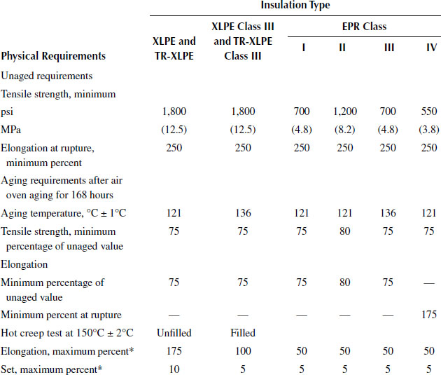
Source: ANSI/ICEA S-94-649, “Standard for Concentric Neutral Cables Rated 5,000–6,000 Volts”, 2004.
* For XLPE and TRXLPE insulations if this value is exceeded, the Solvent Extraction Test may be performed and will serve as a referee method to determine compliance (a maximum of 30 percent weight loss after 20 hour drying time).
TABLE 10.2
Insulation Electrical Requirements
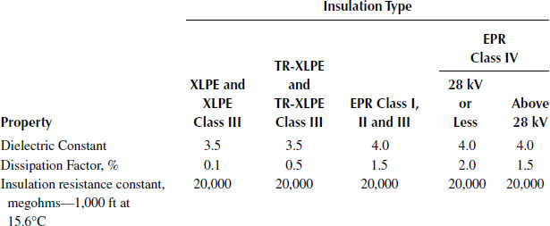
Source: ANSI/ICEA S-94-649, “Standard for Concentric Neutral Cables Rated 5,000–46,000 Volts”, 2004.
RUS specifications require the use of the 133 Percent Level insulation thickness for cables that are manufactured to their needs unless dispensation is given based on the selective designs.
10.5.4 EXTRUDED INSULATION SHIELDS
In addition to the conductor stress control layer, medium voltage, shielded power cables require an insulation shield. The insulation shield consists of a nonmetallic covering directly over the insulation and a nonmagnetic metal component directly over or imbedded in the nonmetallic conducting covering. The insulation shield shall be readily removable in the field at temperatures from −10°C to 40°C. At the option of the purchaser, an insulation shield that is bonded may be supplied. The insulation and the semiconducting material must be compatible since they are in close contact with one another.
The ICEA standard has peel strength limits for the removal of the semiconducting layer for 5 to 46 kV cables. The lower limit is for cable performance, and the upper limit is set to permit removal without damaging the surface of the insulation.
The test calls for a 1/2-inch wide strip to be cut parallel to the center conductor. This cut may be completely through the layer (in contrast to field stripping practices). The 1/2-inch strip is removed by pulling at a 90° angle to the insulation surface at a set rate of speed. The limits are shown in Table 10.3.
TABLE 10.3
ICEA strip Tension Limits
Material |
Lower Limit in pounds (N) |
Upper Limit in pounds (N) |
XLPE and TR-XLPE |
3 (13.4) |
24 (107) |
EPR |
3 (13.4) |
24 (107) |
Source: ANSI/ICEA S-94-649, “Standard for Concentric Neutral Cables Rated 5,000–46,000 Volts”, 2004.
The volume resistivity of the extruded insulation shield shall not exceed 500 ohmmeter at 90°C and 110°C for 90°C rated cables and 105°C and 125°C for 105°C rated cables, when tested in accordance with ICEA procedures. This layer can only be used as an auxiliary shield and requires a metal shield in contact with it to drain off charging currents and to provide electrostatic shielding.
This volume resistivity requirement is half that for the conductor shield, because this layer is subject to chemical action from the environment. The function of the shielding properties would be acceptable with a higher value, but concerns over longtime stability have influenced this level.
The resistivity of the extruded layer is also measured using silver-painted electrodes. The outer coverings including the metallic shield are removed. Four silver-painted annular-ring electrodes are applied to the outer surface of the insulation shield. The inner two electrodes are for the potential application and are at least 2 inches apart. If a high degree of accuracy is required, a pair of current electrodes are placed at least 1 inch behind each potential electrode. The resistance shall be measured between the two potential electrodes. The power of the test circuit shall exceed 100 milliwatts.
The volume resistivity is then calculated as follows:
(10.2) |
where
ρ = volume resistivity in ohm-meters
R = measured resistance in ohms
D = diameter over insulation shield in inches
d = diameter under insulation shield in inches
L = distance between potential electrodes in inches
10.5.4.3 Insulation Shield Thickness
ICEA has established minimum point and maximum point thickness requirements for the extruded insulation shield layer to provide guidance for the manufacturers of molded splices and terminations [14,16].
In addition to the extruded insulation shield previously described, shielded cables must have a nonmagnetic metallic shield over and in contact with the nonmetallic semiconducting layer. The following options are available for the metallic member.
• Helically applied flat tin-coated or uncoated copper tape(s)
• Longitudinally applied corrugated annealed copper tape
• Tin-coated or uncoated copper wire shield (minimum of six #25 AWG or larger)
• Concentric copper wires (#16 AWG or larger to meet neutral cross-sectional area)
• Flat copper straps applied with close coverage to meet neutral cross-sectional area)
• Combination of tape plus wires
• Continuous welded corrugated metal sheath (copper, aluminum, bronze, etc.)
• Extruded lead sheath
Wire shields and flat tapes are popular metallic shields and are almost always copper. A 5-mil copper tape with a minimum 10% overlap is generally used when tapes are specified. For wire shields, #24 to #18 AWG wires are used in proper multiples to provide a minimum of 5,000 circular mils per inch (0.1 mm2/mm) of insulated core diameter. These types have a limited fault current capacity and are not commonly used by electric utilities for outdoor plant for that reason.
Concentric neutral wires and flat straps are normally specified on underground distribution (UD) and underground residential distribution (URD) cables where the metallic shield functions as both a shield and a neutral. These constructions normally use copper wires with an overall jacket applied over the wires for corrosion protection.
In higher voltage cables such as 35 kV to 138 kV, fault currents often may be greater than the capabilities of wires alone. In those situations, the tape plus wire construction is frequently used.
Where metallic shields must be sized for specific fault-clearing requirements, there are several sources of data such as: ANSI/ICEA P-45-482, “Short Circuit Performance of Metallic Shields and Sheaths on Insulated Cable” and EPRI RP 1286-2, (EL-5478), “Optimization of the Design of Metallic Shield/Concentric Neutral Conductors of Extruded Dielectric Cables under Fault Conditions.”
10.5.5.1 Concentric Neutral Cables
ICEA standards cover the number and size of concentric neutral wires for this type of cable. The concentric neutral wires shall be uncoated copper in accordance with ASTM B3 or tin-coated copper in accordance with ASTM B33. The wires of the concentric neutral shall be applied directly over the insulation shield with a lay of not less than six or more than ten times the diameter over the concentric wires.
Although the AEIC specification does not provide information on concentric neutrals, it is important to understand that a full or one-third neutral is not mandated by any standard. Many utilities use fewer neutral wires based on the fact that too much metal leads to increased shield losses. RUS standards do not require even a full neutral for URD cables.
Jackets are generally required over metallic shields for mechanical and corrosion protection during cable installation and operation.
There are many possible jacketing materials such as:
• Low density and linear low density polyethylene, black (LDPE/LLDPE)
• Medium density polyethylene, black (MDPE)
• High density polyethylene, black (HDPE)
• Semiconducting jacket Type I
• Semiconducting jacket Type II
• Polyvinyl chloride (PVC)
• Chlorinated polyethylene (CPE)
• Thermoplastic elastomer (TPE)
• Polypropylene, black (PP)
Their attributes are discussed in Chapter 8. ICEA standards cover the thickness of these jackets.
Numerous documents are available that provide useful information on standards such as: [2,3,4 and 5,7,8,9,10 and 11,13,15,17,18,19,20,21,22,23 and 24].
1. AEIC CS8-07, “Specification for Extruded Dielectric Shielded Power Cables Rated 5 through 46 kV,” Third Edition, 2007, AEIC, 600 North 18th Street, P. O. Box 2641, Birmingham, AL 35291-0992.
2. AEIC CS9-06, “Specification for Extruded Insulation Power Cables and Their Accessories Rated Above 46 kV Through 345 kV AC,” Third Edition, 2006, AEIC, 600 North 18th Street, P. O. Box 2641, Birmingham, AL 35291-0992.
3. ICEA T-22-294, “Test Procedures for Extended-Time Testing of Wire and Cable Insulations for Service in Wet Locations,” 1983, Withdrawn by ICEA.
4. ANSI/ICEA T-24-380, “Standard for Partial Discharge Test Procedures,” 2007, Global Engineering Documents, 15 Inverness Way East, Englewood, CO 80112.
5. ICEA P-32-382, “Short-Circuit Characteristics of Insulated Cable,” 2007, Global Engineering Documents, 15 Inverness Way East, Englewood, CO 80112.
6. ICEA S-61-402/NEMA WC 5, “Thermoplastic Insulated Wire and Cable, 0 to 35 kV,” Withdrawn by ICEA.
7. ICEA T-25-425, “Guide for Establishing Stability of Volume Resistivity for Conducting Polymeric Components of Power Cables,” 2003, Global Engineering Documents, 15 Inverness Way East, Englewood, CO 80112.
8. ANSI/ICEA T-26-465/NEMA WC 54, “Guide for Frequency of Sampling Extruded Dielectric Cables,” 2008, Global Engineering Documents, 15 Inverness Way East, Englewood, CO 80112.
9. ANSI/ICEA P-45-482, “Short Circuit Performance of Metallic Shields and Sheaths on Insulated Cable,” 2007, Global Engineering Documents, 15 Inverness Way East, Englewood, CO 80112.
10. ICEA T-28-562, “Test Method for Measurement of Hot Creep of Polymeric Insulations,” 2003, Global Engineering Documents, 15 Inverness Way East, Englewood, CO 80112.
11. ANSI/ICEA T-27-581/NEMA WC 53, “Test Methods for Extruded Dielectric Cables,” 2008, Global Engineering Documents, 15 Inverness Way East, Englewood, CO 80112.
12. ANSI/ICEA T-31-610, “Test Method for Conducting Longitudinal Water Penetration Resistance Tests on Blocked Conductors,” 2007, Global Engineering Documents, 15 Inverness Way East, Englewood, CO 80112.
13. ICEA T-32-645, “Guide for Establishing Compatibility of Sealed Conductor Filler Compounds with Conductor Stress Control Materials,” 1993, Global Engineering Documents, 15 Inverness Way East, Englewood, CO 80112.
14. ANSI/ICEA S-94-649, “Standard for Concentric Neutral Cables Rated 5,000–46,000 Volts,” 2004, Global Engineering Documents, 15 Inverness Way East, Englewood, CO 80112.
15. ANSI/ICEA T-34-664, “Test Method for Conducting Longitudinal Water Penetration Resistance Tests on Longitudinal Water Blocked Cables,” 2007, Global Engineering Documents, 15 Inverness Way East, Englewood, CO 80112.
16. ANSI/ICEA S-97-682, “Standard for Utility Shielded Power Cables Rated 5,000–46,000 Volts,” 2007, Global Engineering Documents, 15 Inverness Way East, Englewood, CO 80112.
17. ANSI/ICEA S-108-720, “Standard for Extruded Insulation Power Cables Rated Above 46 Through 345 kV,” 2004, Global Engineering Documents, 15 Inverness Way East, Englewood, CO 80112.
18. CAN/CSA-C68.5-07, “Primary and Shielded Concentric Neutral Cable for Distribution Utilities,” 2007, Canadian Standards Association, 5060 Spectrum Way, Suite 100, Mississauga, Ontario, Canada, L4W 5N6.
19. CSA C68.08, “Shielded Power Cable for Commercial and Industrial Applications, 5–46 kV,” 2008, Canadian Standards Association, 5060 Spectrum Way, Suite 100, Mississauga, Ontario, Canada, L4W 5N6.
20. IEC 60502-1, Edition 2.1 2009–11, “Power cables with extruded insulation and their accessories for rated voltages from 1 kV (Um = 1,2 kV) up to 30 kV (Um = 36 kV) — Part 1: Cables for rated voltages of 1 kV (Um = 1,2 kV) and 3 kV (Um = 3,6 kV),” 2009, IEC Central Office, 3 rue de Varembé, P. O. Box 131, CH-1211 Geneva 20, Switzerland.
21. IEC 60502-2, Edition 2.0 2005–03, “Power cables with extruded insulation and their accessories for rated voltages from 1 kV (Um = 1,2 kV) up to 30 kV (Um = 36 kV) — Part 2: Cables for rated voltages from 6 kV (Um = 7,2 kV) up to 30 kV (Um = 36 kV),” IEC Central Office, 3 rue de Varembé, P. O. Box 131, CH-1211 Geneva 20, Switzerland.
22. IEC 60840, Edition 3.0 2004–04, “Power cables with extruded insulation and their accessories for rated voltages above 30 kV (Um = 36 kV) up to 150 kV (Um = 170 kV) — Test methods and requirements,” IEC Central Office, 3 rue de Varembé, P. O. Box 131, CH-1211 Geneva 20, Switzerland.
23. IEC 62067, Edition 1.1 2006–03, “Power cables with extruded insulation and their accessories for rated voltages above 150 kV (Um = 170 kV) up to 500 kV (Um = 550 kV) — Test methods and requirements,” 2006, IEC Central Office, 3 rue de Varembé, P. O. Box 131, CH-1211 Geneva 20, Switzerland.
24. UL Standard 1072, “MV Cables Rated 2,001 to 35,000 Volts,” 2007, Underwriter’s Laboratories, 2600 N. W. Lake Rd., Camas, WA 98607-8542.