
CONTENTS
13.2.1 Introduction to Field Plots
13.2.2 Purpose of a Termination
13.2.3 Termination with Simple Stress Relief
13.2.4 Voltage Gradient Terminations
13.3.2 Voltage Gradient Design
13.3.3 Paper-Insulated Cable Terminations
13.3.5 Separable Connectors (ELBOWS)
13.4.2 Jointing Design and Installation
13.4.2.2 Connecting the Conductors
13.4.2.3 Insulation for Joints
13.6 Selection of Joints and Terminations
A fundamental concept that needs to be established early in this chapter is that when the terms “splice” and “joint” are used here, they are one and the same! “Cable splicers” have been around for over 100 years, but officially in the Institute of Electrical and Electronic Engineers (IEEE) Standards, when you join two cable ends together, you make a joint [1–3].
The basic dielectric theory that has been previously described for cables in Chapter 2 also applies to joints and terminations. Some repetition of those concepts may be presented so that this will be a stand-alone treatment and some repetition is constructive.
This chapter will address the design, application, and preparation of cables that are to be terminated or spliced together. The application of this material will cover medium voltage cable systems in particular with higher and lower voltage applications being mentioned in particular designs and applications. Joints and terminations are expected to perform all of the functions of the cable on which they are installed.
13.2.1 INTRODUCTION TO FIELD PLOTS
Figures that show the electric fields in a cable, splice, or termination are depicted in two ways. Figure 13.1 shows the electric flux lines in a shielded single conductor cable. These lines radiate outward from the center of the conductor toward the grounded shield. The lines are closer together near the conductor, which demonstrates the fact that the electric stress is higher near the conductor. The lines get farther apart near the shield and this shows that the voltage stress is lower near that area.
A plot of equal potential lines (also called equipotential lines) is shown in Figure 13.2. These lines are at right angles to the flux lines described previously. The conductor is shown as having 100% of the impressed voltage and the equipotential lines appear as concentric circles around the conductor. The 75% voltage circle is rather close to the conductor and the subsequent 50% and 25% circles are each spaced a bit farther than the first one. This shows that the voltage difference for a given distance from the conductor is greater there than the same spacing near the shield.
13.2.2 PURPOSE OF A TERMINATION
A termination is a way of preparing the end of a cable to provide adequate electrical, mechanical, and environmental properties. A discussion of the voltage distribution at a cable termination serves as an excellent introduction to this subject.
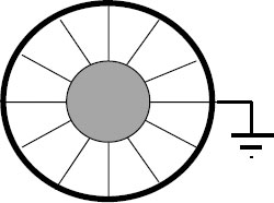
FIGURE 13.1 Electric flux lines in cable.
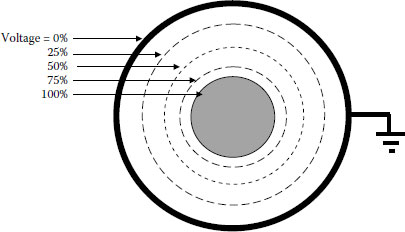
FIGURE 13.2 Equipotential lines in cable.
Whenever a medium or high voltage cable with an insulation shield is cut, the end of the cable must be terminated so as to withstand the electrical stress concentration that is developed when the geometry of the cable has changed. Previously, the electrical stress was described as lines of equal length and spacing between the conductor shield and the insulation shield. As long as the cable maintains the same physical dimensions, the electrical stress will remain consistent. When the cable is cut, the shield ends abruptly and the insulation changes from that in the cable to air. The concentration of electric stress is now at the end of the conductor and insulation shield.
In order to reduce the electrical stress at the end of the cable, the insulation shield is removed for a sufficient distance to provide the adequate leakage distance between the conductor and the shield. The distance is dependent on the voltage involved as well as the anticipated environmental conditions. The removal of the shield disrupts the coaxial electrode structure of the cable. In most cases, the resulting stresses are high enough to cause dielectric degradation of the materials at the edge of the shield unless steps are taken to reduce that stress.
In this operation, the stress at the conductor is reduced by spreading it over a distance. The stress at the insulation shield remains great since the electrical stress lines converge at the end of the shield. The equipotential lines are very closely spaced at the shield edge. If those stresses are not reduced, partial discharge may occur with even the possibility of visible corona. Obviously, some relief is required in most medium voltage applications.
13.2.3 TERMINATION WITH SIMPLE STRESS RELIEF
To produce a termination of acceptable quality for long life, it is necessary to relieve voltage stresses at the edge of the cable insulation shield. The conventional method of doing this has been with a stress cone.
A stress cone increases the spacing from the conductor to the shield. This spreads out the electrical lines of stress as well as provides additional insulation at this high stress area. The ground plane gradually moves away from the conductor and spreads out the dielectric field—thus reducing the voltage stress per unit length. The stress relief cone is an extension of the cable insulation. Another way of saying this is that the equipotential lines are not concentrated at the shield edge as they were in Figure 13.3 and are spaced farther apart. Terminations that are taped achieve this increase in spacing by taping a conical configuration of insulating tape followed by a conducting layer that is connected electrically to the insulation shield. When stress cones are premolded at a factory, they achieve the same result with the concept built into the unit (see Figure 13.4).
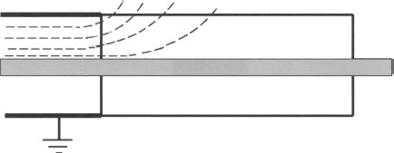
FIGURE 13.3 Equipotential plot, shield removed.
Environmental conditions play a significant role in the length of a termination. Figure 13.5 shows the leakage or creepage distance of a simple stress cone termination. The total distance across any termination defines its leakage distance. A termination with skirts has a creepage distance that includes the whole surface from ground to the energized portion. Figure 13.5 shows the creepage length for a termination.
Experience in a particular area is needed to make good judgments as to this length. When additional leakage distance over the insulation is required, skirts can be placed over the conductor and insulation shield. These skirts can be built into the termination as shown in Figure 13.6 or added in a separate field assembly operation.
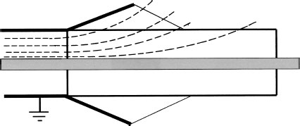
FIGURE 13.4 Stress cone.
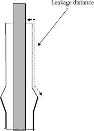
FIGURE 13.5 Creepage/leakage distance.
13.2.4 VOLTAGE GRADIENT TERMINATIONS
Electrical stress relief may come in different forms. A high permittivity material may be applied over the cable end as shown in Figure 13.7. This material may be represented as a long resistor connected electrically to the insulation shield of the cable. By having this long resistor in cylindrical form extending past the shield system of the cable, the electrical stress is distributed along the length of the tube. Stress relief is thus accomplished by utilizing a material having a controlled resistance [4] or capacitance. Other techniques may be employed, but the basic concept is to utilize a material with, say, a very high resistance or specific dielectric constant to extend the lines of stress away from the cable shield edge.
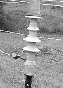
FIGURE 13.6 Cold shrink termination with skirts.
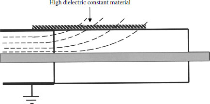
FIGURE 13.7 Stress cones using high K material.
An application of a series of capacitors for stress control is frequently used on high and extra high voltage terminations (138 to 765 kV). These specially formed doughnut-shaped capacitors are used to provide the stress relief. The capacitors are connected in series, as shown in Figure 13.8, and distribute the voltage in a manner that is similar to the high permittivity material that was discussed previously. A stress cone may also be constructed in series and below the capacitors.
The classic approach to the design of a stress relief cone is to have the initial angle of the cone to be nearly zero degrees and take a logarithmic curve throughout its length. This provides the ideal solution, but was not usually needed for the generous dimensions used in medium voltage cables. There is such a very small difference between a straight slope and a logarithmic curve for medium voltage cables that, for hand buildups, a straight slope is completely adequate.
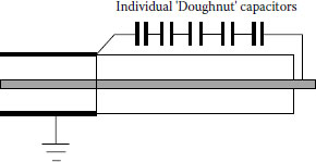
FIGURE 13.8 Capacitive graded termination.
In actual practice, the departure angle is in the range of 3 to 7 degrees. The diameter of the cone at its greatest dimension has generally been calculated by adding twice the insulation thickness to the diameter of the insulated cable at the edge of the shield.
13.3.2 VOLTAGE GRADIENT DESIGN
Capacitive graded materials usually contain particles of silicon carbide, aluminum oxide, or iron oxide. Although they are not truly conductive, they become electronic semiconductors when properly compounded. They do not have a linear E = IR relationship, but rather have the unique ability to produce a voltage gradient along their length when potential differences exist across their length. This voltage gradient does not depend on the IR drop, but on an exchange of electrons from one particle to another.
Resistive graded materials contain carbon black, but in proportions that are less than the semiconducting materials used for extruded shields for cable. They also provide a nonlinear voltage gradient along their length.
By proper selection of materials and proper compounding, these products can produce almost identical stress relief as a stress cone. One of their very useful features is that the diameter is not increased to that of a stress cone. This makes them a very valuable tool for use in confined spaces and inside devices such as porcelain housings.
13.3.3 PAPER-INSULATED CABLE TERMINATIONS
Cables that are insulated with fluid impregnated paper insulation exhibit the same stress conditions as those with extruded insulations. In the buildup of the stress cone, insulating tapes are used to make the conical shape and a copper braid is used to extend the insulation shield over the cone, as shown in Figure 13.9. Similar construction is required on each phase of a three-conductor cable as it is terminated.
The field application of installing stress relief on individual phases can be seen in Figures 13.9 and 13.10. The type of termination is consistent on all types of paper-insulated lead cables (PILC) whether they are enclosed in a porcelain enclosure, a three-conductor terminating device, or inside a switch or transformer compartment (Figure 13.11).
A critical part of the design is the material used to fill the space inside the porcelain or other material that surrounds the paper cable. Since the cable is insulated with a dielectric fluid, it is imperative that the filling compound inside the termination be compatible with the cable’s dielectric fluid. In gas-filled cable designs, the termination is usually filled with the same gas as the cable, but a dielectric fluid may be used in conjunction with a stop gland.
The electrical connection that is used to connect the cable in a termination to another electrical device must be considered. Generally called a “lug,” this connector must be able to carry the normal and emergency currents of the cable, it must provide good mechanical connection in order to prevent from becoming loose and creating a poor electrical connection and it must seal out water from the cable. The water seal is accomplished by two forms of seals. Common to all terminations is the need to keep water out of the strands. Many early connectors were made of a flattened section of tubing that had no actual sealing mechanism and water could enter along the pressed seam of the tubing. Sealing can be accomplished by filling the space between the insulation cutoff and the lug base with a compatible sealant or by purchasing a sealed lug. Figure 13.12 shows one type of terminal lug.
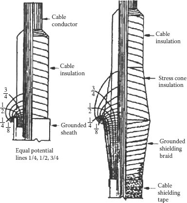
FIGURE 13.9 Equal potential lines, PILC cable with and without stress cones.
The other point that requires sealing is shown in Figure 13.12 that is common to most PILC cable terminations. Here the termination has a seal between the end of the termination and the porcelain body. Another seal that is required is at the end of the termination where the sheath or shield ends. Moisture entering this end could progress along inside the porcelain and result in a failure.
13.3.5 SEPARABLE CONNECTORS (ELBOWS)
One of the most widely used terminations for cables is the “elbow,” as it was originally called, but is more properly called a separable connector. It is unique in that it has a grounded surface covering the electrical connection to the device on which it is used. Used as an equipment termination, it provides the connection between the cable and the electrical compartment of a transformer, switch, or other device. Since the outer surface is at ground potential, this type of termination allows the personnel to work in close proximity to the termination. Another design feature is the ability to operate the termination as a switch. This may be done while the termination is energized and under electrical load. While elbows are available that cannot be operated electrically, this discussion will deal with the operable type that is shown in Figure 13.13. This figure shows a cutaway of a separable connector followed by a brief description of the parts.
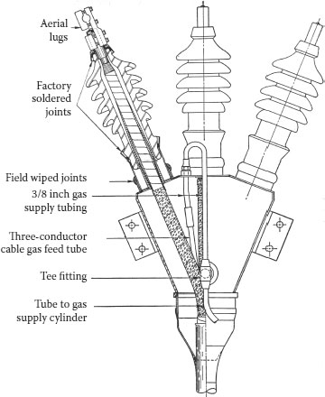
FIGURE 13.10 Gas-filled termination.
The insulating portion of the elbow is made of ethylene–propylene diene monomer (EPDM) rubber with an outer covering of similar material that is loaded with carbon black to make it conductive. The inner semiconducting shields are made of the same material as the outer semiconducting layer.
Probe: The probe consists of a metallic rod with an arc quenching material at the end that enters the mating part, the bushing. The metallic rod makes the connection between the connector and the bushing receptor. Arc quenching material at the tip of the probe quenches the arc that may be encountered when operating the elbow under energized and loaded switching conditions. A hole in the metallic rod is used with a wire wrench to tighten the probe into the end of the cable connector.
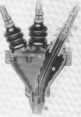
FIGURE 13.11 Three conductor PILC cable termination.
Connector: The connector is attached to the conductor of the cable and provides the current path between the conductor and the metallic probe. It is compressed over the conductor to make a good electrical and mechanical connection. The other end has a threaded hole to accept the threaded end of the probe.
Operating Eye: This provides a place for an operating tool to be attached so that the elbow assembly can be placed into or removed from the bushing. It is made of metal and is molded into the conducting outer layer of the elbow.
Locking Ring: This is molded in the inner surface of the elbow and maintains the body of the elbow in the proper position on the bushing. There is a groove at the end of the bushing into which the locking ring of rubber must fit.
Test Point: Elbows may be manufactured with a test point that allows an approved testing device to determine if the circuit is energized. The test point is in the form of a metallic button that is molded into the elbow body and is simply one plate of a capacitor. It is supplied with a conductive rubber cap that serves to shunt the button to ground during normal service. The molded cap must be removed when the energization test is performed. A second use of the test point is a place to attach a faulted circuit indicator—a device made for test points that may be used to localize a faulted section of circuit for the purpose of reducing the time of circuit outage. When in use, the indicator can remain on the elbow during normal service.
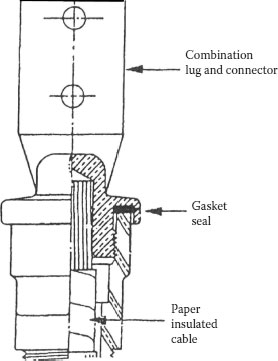
FIGURE 13.12 Terminal lug.
Test Point Cap: Covers and grounds the test point when a test point is specified.
Grounding Eye: This is provided on all molded rubber devices for the purpose of ensuring that the outer conductive material stays at ground potential.
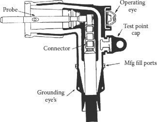
FIGURE 13.13 Load-break elbow. Courtesy Elastimold Div of Thomas and Betts Corp., Memphis, Tennessee.
Operating/Switching: Load-break elbows are designed to function as a switch on energized circuits. They can safely function on cables carrying up to 200 amperes and are capable of being closed into a possible fault of 10,000 amperes. Since this elbow can be operated while energized, devices are required to keep the internal surfaces free of contamination. Good operating practices call for cleaning the mating surfaces of the bushing and the elbow followed by the application of lubricant—while both devices are de-energized! Lubricant is also applied when assembling the elbow on the cable. Some manufacturers supply a different lubricant for the two applications and consequently care should be taken that the correct lubricant is used in each application.
As was mentioned earlier in this chapter, a termination may be considered to be half of a joint. The same concerns for terminations are therefore doubled when it comes to designing and installing a splice.
The ideal joint achieves a balanced match with the electrical, chemical, thermal, and mechanical characteristics of its associated cable. In actual practice, it is not always economically feasible to obtain a perfect match. A close match is certainly one of the objectives.
The splicing or joining together of two pieces of cable can best be visualized as two terminations connected together. The most important deviation, from a theoretical view, between joints and terminations is that joints are more nearly extensions of the cable. The splice simply replaces all of the various components that were made into a cable at the factory with field components. Both cable ends are prepared in the same manner unless it is a transition joint between, say, PILC and extruded cables. Instead of two lugs being attached at the center of the splice, a connector is used. At each end of the splice where the cable-shielding component has been stopped, electrical stress relief is required just as it was when terminating. Figure 13.14 shows a taped splice and its components.
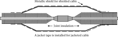
FIGURE 13.14 Taped splice.
Connector: Joins the two conductors together and must be mechanically strong and electrically equal to the cable conductor. In this application, the ends of the connector are tapered. This provides two functions:
1. It provides a sloping surface so that the tape can be properly applied and no voids are created
2. Sharp edges at the end of the connector are not present to cause electrical stress points
Penciling: On each cable being joined, you will notice that the cable insulation is “penciled” back. This provides a smooth incline for the tape to be applied evenly and without voids.
Insulation: In this application, rubber tape is used. Tape is applied to form the stress relief cone at each end of the splice. The overlapped tape continues across the connector to the other side. The thickness at the center of the splice is dictated by the voltage rating.
Conducting Layer: Covering the insulation is a layer of conducting rubber tape that is connected to the insulation shield of the cable at both ends of the splice.
Metallic Shield: A flexible braid is applied over the conducting rubber tape and connects to the factory metallic portion of the cable on each end. This provides a ground path for any leakage current that may develop in the conducting tape.
While not shown in Figure 13.3, there must be a metallic neutral conductor across the splice. This may be in the form of lead, copper concentric strands, copper tapes, or similar materials. It provides the fault current function of the cable’s metallic neutral system.
13.4.2 JOINTING DESIGN AND INSTALLATION
This is the most important step in the entire operation and is the foundation upon which reliable joints and terminations are built. Improperly prepared cable ends provide inherent initiation of failures.
The acceptable tolerances of cable end preparation are dependent upon the methods and materials used to construct the device. Common requirements include a cable insulation surface that is free of contamination, imperfections, and damage caused by such things as shield removal. A smooth surface for extruded dielectric insulations minimizes contamination and moisture adhering to the surface. If the insulation shield can be removed cleanly, there is no reason to use an abrasive on the surface. If a rough surface remains, it must be made smooth.
A cleaning solvent may be needed to obtain an uncontaminated surface. The proper choice of solvent must consider the effect on the person performing the application as well as the cable materials on which it is being applied.
One of the most critical areas is the edge where the insulation shield is removed. A cut into the insulation cannot be remedied and must be removed. For premolded devices, the edge of the shield must be “square”—perpendicular to the cable axis. Metallic connections to the metal shield of the cable must not damage the underlying cable components. Cutting into the strands of wire, or even of greater importance, into a solid conductor, cannot be tolerated.
The concern about the length of the termination is somewhat modified for a joint since the environmental concerns of a termination (external creepage path) are really not a concern for joints. The internal creepage path in a joint is certainly of concern. If you study the literature of the 1950s [5], one finds that the internal creepage path for a paper-insulated cable operating at 15 kV would be 1 inch for every 1 kV. When you look at the design of a premolded joint, you find that the same class of cable has a joint with about 1 inch of creepage—TOTAL. Both of those values are correct. Why is there such a difference? The paper cable was joined using hand applied tapes, either of paper or varnished cloth. There was an air path between the two insulating layers, so the 1 inch per kilovolt was correct. Premolded joints fit very solidly over the cable insulation and use its elastic pressure to maintain the seal. Experience has shown that the approximate 7 kV per inch is reliable for such joints.
13.4.2.2 Connecting the Conductors
Cable conductors are generally either copper or aluminum. Copper is a very forgiving metal in a splice and many methods of connecting two copper conductors together are possible: compression, welding, heat-fusion, soldering (even twisting for overhead conductors 75 years ago), etc. Aluminum connections are not as tolerant as copper. Great care must be taken to match the compression tool, die, and connector with each other for aluminum conductors. As conductor sizes approach 1,000 kcmil these concerns must be addressed more completely. One of the facts involved in the larger size conductors is that, on utility systems especially, the feeder cables are more prone to extended periods of high temperature operation as well as emergency overloads. The operation of the connector must be stable throughout load cycling and be capable of carrying the maximum amount of current without causing thermal degradation of the joint.
The connector metal should be the same as the cable where this is possible. There are situations where this cannot be done, such as the case where a copper conductor is to be connected to an aluminum conductor. It is acceptable to use an aluminum connector over a copper conductor, but a copper connector must not be used over an aluminum conductor because during load cycles, the relative rate of expansion of the two metals causes the aluminum to extrude out and results in a poor connection.
The shape of the connection is always of importance if the connection is not in a shielded area such as those that exist in all premolded splices. In order to minimize voltage stress at the connection for all of those other conditions, special connectors are required for medium and higher voltage cables. Tapered shoulders and filled indents are hallmarks of these connectors. Semiconducting layers are generally specified over these connectors.
13.4.2.3 Insulation for Joints
The material used as the primary insulation in a joint must be completely compatible with the materials in the cable. The wall thickness and its interfaces with the cable insulation must safely withstand the intended electrical stresses. The old rule-of-thumb for paper-insulated cables was that the insulation thickness of the cable was “doubled”. In other words, the designs called for putting a layer equal to twice the factory thickness over the cable insulation. In premolded devices, the thickness is usually about 150% of the factory insulation. The joint insulations for hand taped joints (called self-amalgamating tapes) are predominately made from ethylene–propylene rubber but were originally made of a butyl or polyethylene base as long as the thermal properties matched the cable insulation. Premolded joints are almost always made of ethylene rubber compounds. Heat shrink joints are made of polyolefin compounds that have the property of being able to be expanded after being cross-linked using irradiation. The greater diameter remains until heat is applied to the product as it is in place over the connection.
It is not always a good idea to put on too much insulation. Besides being good electrical insulation, these materials are also good heat barriers. Too much insulation can reduce the ability of the joint to carry the same current as the cable without overheating the center of the joint.
These materials must be compatible with the rest of the cable as well as have adequate conductance to drain off the electrostatically induced voltages, charging currents, and leakage currents. Electromagnetically induced currents and fault currents must also be safely handled across the joint area.
Joint semiconducting shields, like cable shields, achieve their ability to perform the task of electrical shielding by having a considerable amount of carbon black (about 30%) compounded into the material. These particles do not actually have to touch each other in order to be conductive.
They must provide physical strength, seal against moisture entry into the splice, and resist chemical and other environmental attacks. It is important to use a jacket over the splice when jacketed cables are spliced together since corrosion of metallic neutrals or shields may concentrate at this point.
The manufactured splice shown in Figure 13.15 has essentially the same component requirements of the taped splice. These devices are designed to cover the range of medium voltage cable sizes. It is essential that the specified cable diameters of the splice be kept within the specified size range of each of the cables. The body of the splice must be slid over one of the cable ends prior to the connector being installed. It is finally repositioned over the center of the joint.
The components of this type of splice are listed as follows:
Connector: The connector shown indicates that it was mechanically pressed on the conductors. In addition, the ends of the connector are not tapered, nor is that a requirement when covered by a connector shield.
Cable End Preparation: The insulation of the cable at the connector is now cut at right angle to the conductor. In the taped splice, a penciled end was required for proper application of tapes. However, in this design, there is no taping required and consequently a pencil is not required. A chamfer is required to remove any sharp edges of the cable to prevent the scratching of the inner surface of the splice housing and to make it easier to slide the splice body into position.
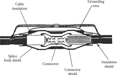
FIGURE 13.15 Premolded splice. Courtesy of Thomas and Betts Corp., Memphis, Tennesseee.
Connector Shield: This component is not found in this form in a taped splice, but is critical to the performance of a premolded splice. It is composed of conducting rubber material. In order to nullify the sharp edges of the connector and the air that is between the connector and the cable insulation, this connector shielding must make electrical contact with the cable conductor to eliminate any voltage difference that exists. When the connector shield makes contact with the connector and the cable is energized, both the connector and the shield material are at the same potential. With this design, no discharges can occur in the air or at the connector edges. Figure 13.16 gives an expanded view of the connector shield and its application over a connector.
Insulation: The EPDM insulation is injected between the connector shield and the outer conducting shield of the splice body.
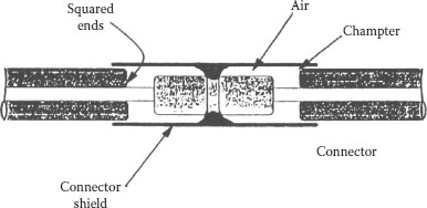
FIGURE 13.16 Detail of connector area of premolded splice.
Splice Body Shield: This is a thick layer of conducting rubber. It is designed to overlap the cable’s conducting insulation shield on each end of the splice and to provide stress relief at both cable ends.
Grounding Eye: At each end of the splice, a grounding eye is required on all medium voltage premolded devices and they must be connected to the cable neutral. This provides a parallel path for the grounding of the splice body shield.
Neutral Across Splice: This generally consists of concentric strands from the cable that are twisted together and joined at the center of the splice. The wire used to make an electrical connection to the molded eye is shown connected to the neutral connector and to the concentric strands at each end of the splice.
In an actual field application, these strands should spiral around the splice and be in contact with the outer layer of the splice. This facilitates fault locating by providing a reliable metallic ground for the splice shield.
Adapters: Some designs of premolded splices incorporate adapters. They extend the range of cables that can be accommodated in a specific housing. They also permit the jointing of two widely different cable sizes and they also may enable the user to minimize the inventory of housings. Positioning of the adapter is important so that electrical stress points are not introduced. Adapters are applied before the connector is installed and as in the case of other premolded splices, the body must also be installed prior to the connection and the entire assembly is moved into place.
There are many ways of producing a joint or termination for medium voltage cables: hand applied tapes, combinations of premolded stress cones and hand applied tapes, premolded, cold shrink, resin filled, and heat shrink—just to mention some of them. The proper choice of which termination to select for a given application must consider factors such as cost of materials, time of installation, frequency of use, reliability, space requirements, and skill of the installer. Obviously, there is no universal solution to the wide variety of needs and conditions that are encountered in the field. The proper selection of a joint must consider all of these.
Field molded splices are constructed somewhat like a conventional taped splice. The insulating material is an uncured rubber material that may come in the form of tape or preformed sections. When the proper amount of material has been applied, the splice body is enclosed in a temperature controlled “oven” that confines the expanding material to the proper temperature and time required to cure the tapes. Stress relief is maintained by utilizing a conductive paint over the connector and the insulation after it is cured. The remainder of the shielding and neutral system is restored in the normal manner.
Heat shrink splices are available as a series of heat shrinkable tubes. Some may be preassembled by the manufacturer to reduce the number that must be handled in the field. The tubes must be slipped over the cable prior to connecting the conductors. After positioning each tube over the connected cables, heat is applied to shrink the tube snugly over the underlying surface and soften any mastic material used in the assembly. Stress relief is generally provided by stress control tubes that are also shrunk into place so that ends of the stress control tube overlap both cable insulation shields. The joint is finished in the normal manner.
Cold shrink splices are similar except that a removable liner is pulled out and the tube collapses over the underlying surface. As the name implies, no heat is required. Medium voltage joints contain all the necessary electrical components.
13.6 SELECTION OF JOINTS AND TERMINATIONS
When making a decision as to the best choice of devices to purchase, here are some of the questions and opportunities that should be considered:
• Are the components of the device compatible with the cable being spliced or terminated?
• Did the device pass all the tests that were specified so that it meets the requirements of the electrical system involved?
• Are codes applicable in the decision to use the chosen device?
• Review all safety requirements involved in the construction, application, and installation of the device.
• Will the device meet the mechanical requirements of the installation?
• Can the device be assembled with the tooling that is already available or are special tools required?
• Consider the positioning of the device. Splices are not recommended for installation at bends in the cable. Terminations are normally installed in an upright position. Other positions are possible but require special attention.
• Environmental conditions are of importance to attain expected life of any device. Heat may affect the ampacity of the device. Cold may have an effect on the assembly during installation. Contaminants are critical to the leakage path of a termination.
• Moisture is always the enemy of an underground system and must be controlled in construction and installation.
• Are there any existing work practices or procedures that will conflict with the application of this device?
• Investigate the economics of using different devices such as emergency reserve parts, training new personnel after original installation personnel have gone.
• The cost of the device and the cost of installation.
• Will the device do the job as well or better than what is presently used?
Failures happen in spite of all the effort to properly design, make, and operate cable systems. A useful document to aid in the collection of necessary information after a failure is available from IEEE: IEEE 1511-2004, “Guide for Investigating and Analyzing Power Cable, Joint, and Termination Failures” [6].
1. Medek, J. D., 2001, adapted from class notes for “Understanding Power Cable Characteristics and Applications,” University of Wisconsin–Madison.
2. Balaska, T. A., January 1992, adapted from class notes for “Power Cable Engineering Clinic,” University of Wisconsin–Madison.
3. Balaska, T. A., 1974, “Jointing of High Voltage, Extruded Dielectric Cables, Basics of Electrical Design and Installation,” IEEE UT&D Conference Record, pp. 318–326.
4. Virsberg, L. G. and Ware, P. H., 1967, “A New Termination for Underground Distribution,” IEEE Transactions, Vol. PAS-86, pp. 1129–1135.
5. Underground Systems Reference Book, EEI, 1957.
6. IEEE 1511-2004, “Guide for Investigating and Analyzing Power Cable, Joint, and Termination Failures.”