
CONTENTS
16.3.3 Bonding Jumper Capability
16.5 Single-Point and Cross-Bonding
16.5.4 Single-Point Bonding Methods
16.5.5 Induced Sheath Voltage Levels
16.5.6 Depiction of Bonding Methods
16.5.6.1 Multigrounded Cable Run—Two or More Grounds. Solid, Multigrounded Circuits
16.5.6.2 Cross-bonded Circuits
16.5.6.3 Continuous Cross-Bonding
16.5.6.4 Auxiliary Cable Bonding
16.5.6.5 Continuous Cross-Bonding, Star Ground
This discussion provides an overview of the reasons and methods for reducing sheath losses in large cables. While calculations are shown, all of the details are not covered as completely as in the Institute of Electrical and Electronics Engineers (IEEE) Guide 575 [1]. A complete set of references is included in that standard. The reader is urged to obtain a copy of the latest revision of that document before designing a “single-point” grounding scheme. Another excellent reference is the 1957 Underground Systems Reference Book [2].
The terms sheath and shield will be used interchangeably since they have the same function, problems, and solutions for the purpose of this chapter.
• Sheath refers to a water impervious, tubular metallic component of a cable that is applied over the insulation. Examples are a lead sheath and a corrugated copper or aluminum sheath. A semiconducting layer may be used under the metal to form a very smooth interface.
• Shield refers to the conducting component of a cable that must be grounded to confine the dielectric field to the inside of the cable. Shields are generally composed of a metallic portion and a conducting (or semiconducting) extruded layer. The metallic portion can be tape, wires, or a tube.
The cable systems that should be considered for single-point grounding are systems with cables of 1,000 kcmils and larger and with anticipated loads of over 500 amperes. Fifty or more years ago, those cables were the paper-insulated transmission circuits that always had lead sheaths. Technical papers of that era had titles such as “Reduction of Sheath Losses in Single-Conductor Cables” [3] and “Sheath Bonding Transformers” [4]; hence, the term “sheath” is the preferred word rather than “shield” for this discussion.
Chapter 4 described how a cable is a capacitor. That is true. Now you must think about the fact that a cable may also be a transformer.
When alternating current flows in the “central” conductor of a cable, that current produces electromagnetic flux in the metallic shield when present, or in any parallel conductor. This becomes a “one-turn” transformer when the shield is grounded two or more times since a circuit is formed and current flows.
We will first consider a single, shielded cable:
• If the shield is only grounded one time and a circuit is not completed, the magnetic flux produces a voltage in the shield. The amount of voltage is proportional to the current in the conductor and increases as the distance from the ground increases (Figure 16.1).
• If the shield is grounded two or more times or otherwise completes a circuit, the magnetic flux produces a current flow in the shield. The amount of current in the shield is inversely proportional to the resistance of the shield. In other words, the current in the shield increases as the amount of metal in the shield increases. The voltage stays at zero (see Figure 16.2).
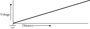
FIGURE 16.1 Single-point grounding.
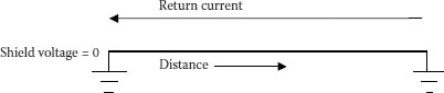
FIGURE 16.2 Two or more grounds.
The voltage remains at zero, but the same current flows regardless of the distance between the grounds.
An important concept regarding multiple grounds is that the distance between the grounds has no effect on the magnitude of the current. If the grounds are 1 foot apart or 1,000 feet apart, the current is the same depending on the current in the central conductor and the impedance of the shield. In the case of multiple cables, the spatial relationship of the cables is also a factor.
One method of single-point grounding of a run of cable is to ground in the center of the run—leaving both terminals having energized shields. This reduces the standing voltage by half as compared with grounding one end of that circuit (Figure 16.3) [12].
In Chapter 14, there is a complete description of ampacity and the many sources of heat in a cable such as conductor, insulation, shields, etc. See Chapter 15 to know how this heat must be carried through conduits, air, concrete, surrounding soil, and finally to ambient earth. If the heat generation in any segment is decreased, such as in the sheath, then the entire cable will have a greater ability to carry useful current. [5–7] (Note: The heat flow is always up toward the earth’s surface.)
The heat source from the shield system is the one that we will concentrate on, in this discussions, as we try to reduce or eliminate it [13].
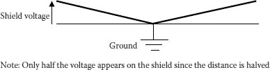
FIGURE 16.3 Center ground only.
When an AC current flows in the conductor of a single-conductor cable, a magnetic field is produced. If a second conductor is within that magnetic field, a voltage that varies with the field will be introduced in that second conductor, in our case, the sheath.
If that second conductor is part of a circuit (connected to ground in two or more places), the induced voltage will cause a current to flow. That current generates losses that appear as heat. The heat must be dissipated the same way as the other losses. Only so much heat can be dissipated for a given set of conditions, so that these shield losses reduce the amount of heat that can be assigned to the phase conductor.
Let us assume that we are going to ground the shield at least two times in a run of cable. What is the effect of the amount of metal in the shield?
The following curves present an interesting picture of the shield losses for varying amounts of metal in the shield. These curves are taken from ICEA document P 53-426 [7]. As you can see, they were concerned about underground residential distribution (URD) cables where the ratio of conductivity of the shield was given as a ratio of the conductivity of the main conductor; hence, one-third neutral.
In the situation where 2,000 kcmil aluminum conductors are triangularly spaced 7.5 inches apart, the shield loss for a one-third neutral is 1.8 times the conductor loss!
For single-conductor transmission cables having robust shields, losses such as these are likely to be encountered in multipoint grounding situations and are generally not acceptable.
The shield, or sheath, of a cable must have sufficient conductivity in metal to carry the available fault current that may be imposed on the cable. Single-conductor cables should have enough metal in their shields to clear a phase-to-ground fault and with the type of fusing or reclosing scheme that will be used. It is not wise to depend on the shields of the other two phases since they may be some inches away. You need to determine:
• What is the fault current that will flow along the shield?
• What is the time involved for the backup device to operate?
• Will the circuit be reclosed and how many times?
Too much metal in the shield of a cable section with two or more grounds is not a good idea. It involves additional cost to buy such a cable and the losses not only reduce the ampacity of the cable but also cause undue economic losses from the heat produced [10,11].
One way that you can test your concept of a sufficient amount of shield is to look at the performance of the cables that you have in service. Even if the present cable has a lead sheath, you can translate that amount of lead to copper equivalent. You will also need to consider what the fault current may be in the future. The Electric Power Research Institute (EPRI) has developed a program that does the laborious part of the calculations.
We can “convert” metals used in sheaths or shields to copper equivalent by measuring the area of the shield metal and then translate that area to copper equivalent using the ratio of their electrical resistivities (Table 16.1).
TABLE 16.1
Electrical Resistivity of Metals
Metal |
Electrical Resistivity in Ohm-mm2/m × 10−8, 20°C |
Copper, annealed |
1.724 |
Aluminum |
2.83 |
Bronze |
4.66 |
Lead |
22.0 |
Iron, hard steel |
24.0 |
As an example, we have a 138 kV low pressure oil-filled (LPOF) cable that has a diameter of 3.00 inches over the lead and the lead is 100 mils thick.
The area of a 3.00 inch circle is = 7.0686 in2
The area of a circle that is under the lead is:
Diameter = 3.00 − 0.100 − 0.100 = 2.80 in
Area = 1.4 × 1.4 × π = 6.1575 in2
Area of the lead is 7.0686 − 6.1575 = 0.9111 in2
The ratio of resistivities is 1.724/22.0 = 0.0784
The copper equivalent is 0.9111 in2 × 0.0784 = 0.07139 in2
To convert to circular mils, multiply inches squared by 4/π × 106 = 90,884 cmils
This lead sheath is between a #1/0 AWG (105,600 cmils) and a #1 AWG (83,690 cmils)
If the sheath increases to 140 mils and the core stays the same, we have:
The area of the sheath is = 7.4506 in2
The area of lead is 7.4506 − 6.1575 = 1.2931 in2
Multiply by the same ratio of 0.0784 = 0.1014
To convert to circular mils, multiply by 4/π × 106 = 129,106 cmils
This is almost a #2/0 AWG (133,100 cmils) copper conductor
Using the same concept, one can change from aluminum to copper, etc.
The allowable short-circuit currents for insulated copper conductors may be determined by the following formula:
(16.1) |
where
I = short circuit current in amperes A = conductor area in circular mils
t = time of short circuit in seconds
T1 = operating temperature, 90°C
T2 = maximum short-circuit temperature, 250°C
A well-established plot of current versus time is included in [9]. It is important to be aware that these results are somewhat negative since the heat sink of coverings is ignored and has not been addressed in Equation 16.1. On the other hand, the answers given are safer values.
16.3.3 BONDING JUMPER CAPABILITY
A good connection must be made between the bonding jumper and the cable sheath to have enough capacity to take the fault current to ground or to the adjacent section—no matter how well-designed is the cable sheath. This is frequently a weak point in the total design. Another area of concern is the point of attachment of the bond wire to the sheath.
The bonding jumper should always be of the size greater than the equivalent sheath area and should be as short and straight as possible to reduce the impedance of that portion of the circuit. In all cases, the bonding jumper should be a covered wire, such as a 600 volt building wire, to improve its short-term ampacity.
☺ No sheath isolation joints
☺ No voltage on the shield
☺ No periodic testing is needed
☺ No concerns when testing or looking for faults
☹ Lower ampacity
☹ Higher losses
Although you may have already decided to drop this concept, you should be aware of the consequences of a second ground or connection appearing on a run of cable that had not been planned. Such a second ground can complete a circuit and result in very high sheath currents that could lead to a failure of all of the cable that has been subjected to those currents. The higher the calculated voltage on the sheath, the greater the current flow may be in the event of the second ground. Periodic maintenance of single-point grounded circuits should be considered. If this is to be done, a graphite layer over the jacket will enable the electrical testing of the integrity of the jacket.
16.5 SINGLE-POINT AND CROSS-BONDING
To be precise, single-point grounding means only one ground per phase, as will be explained later. Cross-bonding also limits sheath voltages and demonstrates the same advantages and disadvantages as single-point grounding.
☺ Higher ampacity
☺ Lower losses
☹ Sheath isolation joints are required
☹ Voltage on sheath/safety concerns
The term that was used to describe single-point grounding during the 1920s to 1950s was open-circuit sheath. The concern was to limit the induced sheath voltage on the cable shield. A 1950s handbook said that “The safe value of sheath voltage above ground is generally taken at 12 volts AC to eliminate or reduce electrolysis and corrosion troubles.” The vast majority of the cables in those days did not have any jacket—just bare lead sheaths. Corrosion was obviously a valid concern. (Some US cable manufacturers still recommend 25 volts as the maximum for most situations.) The vastly superior jacketing materials that are available today have helped change the currently accepted value of “standing voltage” to 100 to 400 volts for normal load conditions. Since the fault currents are much higher than the load currents, it is usually considered that the shield voltage during fault conditions be kept to a few thousand volts. This is controlled by using sheath voltage limiters—a type of surge arrester.
16.5.4 SINGLE-POINT BONDING METHODS
There are numerous methods of managing the voltage on the shields of cables with single-point grounding. All have one thing in common: the need for a sheath or shield isolation joint.
Five general methods will be explored:
• Single-Point Grounding
• Cross-Bonding
• Continuous Cross-Bonding
• Auxiliary Bonding
• Series Impedance or Transformer Bonding
Diagrams of each method of connection, with a profile of the voltages that would be encountered, are shown in Section 16.5.6.
There are other types of grounding schemes that are possible and are in service. Generally, they make use of special transformers or impedances in the ground leads that reduce the current because of the additional impedance in those leads. These were necessary years ago when the jackets of the cables did not have the high electrical resistance and stability that are available today.
16.5.5 INDUCED SHEATH VOLTAGE LEVELS
Formulas for calculating shield voltages and current and losses for single-conductor cables were originally developed by K. W. Miller in the 1920s [3]. The same general equations are also given in several handbooks. The table from Reference [7] is included as Figure 16.7. The difference in these equations is the use of the “j” term—to denote phase relationship—so only the magnitude of the voltage (or current) is determined. Each case that follows will include the formulas from reference [7,8].
The induced voltage in the sheath of one cable or for all cables in a circuit where the cables are installed as an equilateral triangle is given by:
(16.2) |
where
Vsh = sheath voltage in microvolts per foot of cable
I = current in a phase conductor in amperes
Xm = mutual inductance between the conductor and the sheath
The mutual inductance for a 60 hertz circuit may be determined from the formula:
(16.3) |
where
Xm = mutual inductance in micro-ohms per foot
S = cable spacing in inches
rm = mean radius of the shield in inches. This is the distance from the center of the conductor to the mid-point of the sheath or shield.
For the more commonly encountered cable arrangements such as a three-phase circuit, other factors must be brought into the equations. Also, A and C phases have one voltage while B phase has a different voltage. This assumes equal current in all phases and a phase rotation of A, B, and C.
Right-angle or “rectangular” spacing is a probable configuration for large, singleconductor cables in a duct bank. One arrangement is shown in Figure 16.4.
The induced shield voltages in A and C phases are:
(16.4) |
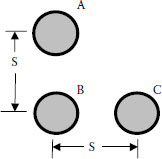
FIGURE 16.4 Right angle arrangement.
where
Vsh = sheath voltage on A and C phases in volts to neutral per foot I = current in phases conductor in amperes
Y = Xm + A/2
Xm = 52.92 log10 S/rm for 60 hertz operation
S = spacing in inches
A = 15.93 micro-ohms per foot for 60 hertz operation
The induced shield voltage in B phase is:
(16.5) |
A flat configuration is commonly used for cables in a trench, but this could be a duct bank arrangement as well (Figure 16.5).
The induced shield voltages in A and C phases are:
(16.6) |
where
Vsh = sheath voltage on A and C phases in volts to neutral per foot
I = current in phases conductor in amperes
Y = Xm + A [This factor has changed from Equation 16.4)!!!]
Xm = 52.92 log10 S/rm for 60 hertz operation
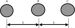
FIGURE 16.5 Flat arrangement.
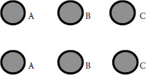
FIGURE 16.6 Two circuits, flat configuration.
S = spacing in inches
A = 15.93 micro-ohms per foot for 60 hertz operation
The induced shield voltage in B phase is the same as Equation 16.5 (Figure 16.6):
(16.7) |
The induced shield voltages in phases A and C are:
(16.8) |
where
Vsh = sheath voltage on A and C phases in volts to neutral per foot
I = current in phase conductors in amperes
Y = Xm + A + B/2 [This factor has changed again!]
Xm = 52.92 log10 S/rm for 60 hertz operation
S = spacing in inches
A = 15.93 micro-ohms per foot for 60 hertz operation
B = 36.99 micro-ohms per foot for 60 hertz operation
The induced shield voltage for B phase is (Figure 16.7):
(16.9) |
The induced shield voltages in phases A and C are similar to Equation 16.7, but Y changes:
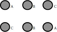
FIGURE 16.7 Two circuits, flat configuration, phases opposite.
(16.10) |
where
Vsh = sheath voltage on A and C phases in volts to neutral per foot
I = current in phases conductor in amperes
Y = Xm + A − B/2 [Now a minus, not +]
Xm = 52.92 log10 S/rm for 60 hertz operation
S = spacing in inches
A = 15.93 micro-ohms per foot for 60 hertz operation
B = 36.99 micro-ohms per foot for 60 hertz operation
The induced voltage on B phase uses the same equation as Equation 16.9:
(16.11) |
16.5.6 DEPICTION OF BONDING METHODS
16.5.6.1 Multigrounded Cable Run—Two or More Grounds. Solid, Multigrounded Circuits
Three-conductor cables should always be solidly grounded in each manhole using a grounding conductor of sufficient size to carry the available fault current for the time dictated by the clearing relays and equipment. A similar grounding system should be utilized for most single-conductor cables, but ampacity concerns may dictate another grounding method.
A schematic diagram of a multigrounded system is shown in Figure 16.8.
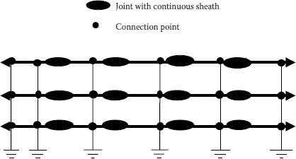
FIGURE 16.8 Multigrounded cable runs.
16.5.6.2 Cross-bonded Circuits
The goal of any shield isolation system is to reduce induced shield currents to the point that they will not seriously affect the ampacity of the circuit and to limit the sheath voltage to a safe value. For large single-conductor cables designed to carry 500 amperes or more, consideration should be given to the several alternative grounding systems that are available.
The most commonly used is cross-bonding where the cable circuit is divided into three equal sections (or six, or nine, etc.). The shield is solidly grounded at the beginning of the first section and at the end of the third section. The second section is isolated by means of shield “breaks” from the first and third sections and has its sheath bonded to other phases (see Figure 16.9).
The induced shield voltage from A phase is “cross-bonded” to B phase. This phase change reduces the resultant sheath voltage, and so on, for all sections of the circuit.
Bonding conductors must have sufficient capacity to carry the fault current that will be imposed and voltage resistance to keep the bonding jumper from being inadvertently grounded.
This method has the disadvantage of needing the joints evenly spaced through each triple section. When the joints are not evenly spaced, the voltage from one phase does not completely cancel out the other phase. This may not be critical, but it does mean that somewhat higher voltage levels will result.
16.5.6.3 Continuous Cross-Bonding
This is basically the same as the cross-bonding of Section 16.5.6.2 except that all of the joints have shield interruption provisions. Such a scheme is useful in situations where the triple sections are not practical from a field standpoint, such as for four sets of joints—where the matched sets of three are not attainable.
The sheath voltages are approximately the same as for cross-bonded circuits. A disadvantage of this system is that there are no solid grounds except at the terminations.
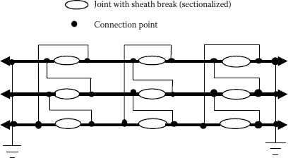
FIGURE 16.9 Cross-bonding connections.
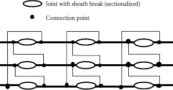
FIGURE 16.10 Continuous cross-bonding.
Longer circuits may require that continuous cross-bonding be used where the sections are divided into sets of three sections of cable. This is shown in Figure 16.10.
16.5.6.4 Auxiliary Cable Bonding
Sheath losses may be controlled by installing sheath insulators in every splice and then grounding one point on each cable to a parallel “auxiliary” cable. An additional duct is required. This arrangement is shown in Figure 16.11.
This system is similar to the continuous cross-bonding method since all the joints must have shield isolation and all shields are bonded at each splice. The unique part of this arrangement is that the shields are connected to each other and to a separate neutral cable that runs along the length of the circuit.
This permits the through fault current to be transmitted on both the shield as well as the parallel neutral cable. A reduction in the amount of shield materials is thus possible. A cable fault must still be cleared by having the fault current of that phase taken to ground at a remote point. This means that you must still put on a sufficient amount of shield metal to permit the breaker, or other backup device, to “see” the fault.
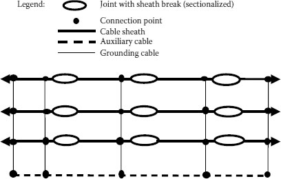
FIGURE 16.11 Auxiliary cable bonding.
16.5.6.5 Continuous Cross-Bonding, Star Ground
This system and other impedance type systems have been included in this discussion since they have been employed over the years. The basic need for these systems was to keep the sheath voltage down to very low value of 12 volts. Now that over 100 volts is considered safe and reliable, the complication of these systems does not seem to be worthwhile. The equipment needed to accomplish these hookups are not very easy to find, have not been too reliable, and take up room in a manhole that is at a premium. Another concern is that these devices require additional maintenance time to be certain that they remain operational.
1. IEEE Std. 575-1988, IEEE Guide for the Application of Sheath-Bonding Methods for Single-Conductor Cables and the Calculation of Induced Voltages and Currents in Cable Sheaths.
2. Underground Systems Reference Book, EEI, 1957.
3. Halperin, H. and Miller, K. W., April 1929, “Reduction of Sheath Losses in Single-Conductor Cables”, Transactions AIEE, p. 399.
4. Sheath Bonding Transformers, Bulletin SBT 2, H. D. Electric Co., Chicago, IL.
5. AIEE-IPCEA Power Cable Ampacities, AIEE Pub. No. S-135-1 and -2, IPCEA P-46-426, 1962.
6. IEEE Standard Power Cable Ampacities, IEEE 835-1994.
7. ICEA P-53-426.
8. Engineering Data for Copper and Aluminum Conductor Electrical Cables, Bulletin EHB-90, The Okonite Company.
9. IEEE Std. 532-1993 ISBN 1-55937-337-7, IEEE Guide for Selection and Testing Jackets for Underground Cables.
10. EPRI EL-3014, RP 1286-2, “Optimization of the Design of Metallic Shield / Concentric Neutral Conductors of Extruded Dielectric Cables Under Fault Conditions.”
11. EPRI EL-5478, “Shield Circulating Current Losses in Concentric Neutral Cables.”
12. “Sheath Over-voltages in High Voltage Cable Due to Special Sheath Bonding Connections,” IEEE Transactions on Power Apparatus and Systems, Vol. 84, 1965.
13. “The Design of Specially Bonded Cable Systems,” Electra, (28), CIGRE Study Committee 21, Working Group 07, May, 1973.