
CONTENTS
19.3.1 Mechanisms of Water Treeing
19.3.1.3 Examples of water Trees
19.3.1.4 Methods to Minimize Water Treeing
19.3.2 Introduction to Accelerated Testing
19.5 Combinations of Electrical and Water Trees
19.7 Technical Discussion of Treeing
19.8 Methylene Blue Dying Technique
19.9 Observation in Silicone Oil
Treeing in extruded dielectric cable insulation is the term that has been given to a type of electrical prebreakdown deterioration that has the general appearance of a tree-like path through the wall of insulation. This formation is radial to the cable axis and hence is in line with the electrical field.
Trees form in insulations such as polyethylene, cross-linked polyethylene (XLPE), and ethylene–propylene rubber (EPR) cables and are considered as two distinct types:
• Water trees (also known as electrochemical trees)
• Electrical trees
They are differentiated by the distinctions shown next and other parameters that will be discussed in detail later in this chapter.
Water Trees
• Diffuse, indistinct small voids separated by somewhat deteriorated insulation
• Moisture is required
• Slow growth (months, years)
• Must be stained to see them. This may be from chemicals in or around the cable or be stained while the cable is examined
• May exist without immediate electrical failure
Electrical Trees
• Distinct hollow channels
• Water not required
• Rapid growth (seconds, minutes, hours)
• Electrical failure occurs very quickly
The phenomenon known as treeing in dielectrics was first described by Rayner in 1912 [1]. He had been investigating electrical breakdown in the presence of discharges in paper-insulated cables. The tree-like appearance of Lichtenberg figures was well known during the 1920s. These “trees” are totally different from what is seen in extruded dielectric cables because those older trees were carbon paths burned into the paper insulation that proceed concentrically around the insulating wall. In Figure 19.1, six adjacent tapes are shown together.
Treeing in extruded dielectric cables was described by Whitehead [2] in 1932 in his work on electrical breakdown. The development of corona detection equipment in 1933 by Tykociner, Brown, and Paine [3] made quantitative studies possible. Kreuger [4] thoroughly described the methods for detection and measurement of discharges in 1965.
The announcements by Vahlstrom and Lawson [5,6] in 1971 and 1972 that direct buried high molecular weight polyethylene (HMWPE) cables installed in the field in underground residential distribution (URD) systems contained water trees made a significant impact on the cable industry. This was the first time that this type of treeing had been reported in a typical utility environment. Previously reported results, especially by the Japanese [7] that they called “sulfide trees,” now became required reading.
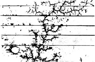
FIGURE 19.1 Tree-like deterioration in paper insulation. Courtesy of University of Wisconsin–Madison.
Up until that time, mechanical damage was considered to be the predominant mechanism of failure for cables in a utility installation. The remaining 10% were thought to be due to unknown causes that were not necessarily due to electrical deterioration in the cable.
Water (also called electrochemical or chemical) trees form at a slow rate that may take many years to propagate and grow. Water trees can occur in all solid (extruded) dielectric materials. The tree-like appearance can be described by reference to many natural shapes that are sometimes obvious upon cutting wafers from aged cables. Examples are shown later in this chapter.
The visibility of water trees stems from the staining of the interior of the tree wall by some form of chemical staining. Nonstained water trees disappear when the sample is dried. Staining techniques are discussed later in this chapter.
Water treeing is influenced by the following:
Moisture (an essential ingredient!)
Voltage stress
Voids
Contaminants
Ionic impurities
Temperature
Temperature gradient
Aging time
PH
19.3.1 MECHANISMS OF WATER TREEING
There are three stages in the development of water trees in extruded insulation:
• Inception
• Conversion/electrical breakdown
Laboratory investigation of water tree inception has demonstrated that several probable mechanisms are involved:
1. Voltage stress concentration at a very small void or contaminant can be orders of magnitude higher than the average electrical stress at that location. Although very sensitive measuring equipment has been utilized (about 0.05 pC sensitivity), no partial discharge has been detected during this stage of inception or growth. Electron bombardment in such a cavity is capable of erosion of the dielectric in the cavity.
2. Mechanical stress can be produced by very high electrical fields around an electrical stress concentration. This may result in fatigue and the development of stress cracks in the dielectric. Partial discharges in such cracks may lead to local electrical breakdown and tree formation.
3. Electron bombardment can be sufficiently high to cause a cavity to form due to ionization of the dielectric that causes chain scission and decomposition.
4. Local intrinsic breakdown of the dielectric.
None of these, by itself, can explain the results of laboratory studies, so it is probable that initiation of a water tree involves more than one mechanism. The effect of high electrical stress is universally accepted, however.
Propagation or growth of water trees seems as elusive as inception. Only the presence of an alternating current (AC) electrical field seems to be a unifying conclusion. Although direct current (DC) can produce water trees, it is at a much slower rate and with a different shape. It is well established that polymers are readily permeable by moisture and that the presence of moisture in these insulations is deleterious.
Two significant forces to explain the penetration of moisture through extruded dielectrics are:
1. Electrophoresis is a term used to describe the movement of charged particles in an electric field. Particles with a positive charge tend to move toward a negative electrode, while negative ions tend to move toward the positive electrode. A practical application of this theory when DC testing a cable is to place the negative charge on the conductor. This pulls moisture in toward the center of the cable and makes the test more definitive.
2. Dielectrophoresis describes the movement of uncharged but polarized particles or molecules in a divergent field (Figure 19.2). In the example of an otherwise uniform single-conductor electrical cable, the field increases as a particle or molecule gets closer to the conductor. An uncharged particle will be polarized at any given point of time so that it will have a negatively charged dipole with its negative side, for instance, toward the conductor that is positive at that instant. Since the negative side of this dipole exists in a stronger field than the positive side, the particle will be attracted toward the field of greatest field intensity. In an AC system, as the conductor becomes negatively charged, the polarization process is reversed. This means that the particle is still attracted toward the conductor with its higher electric field.
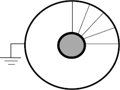
FIGURE 19.2 Dielectrophoresis.
The practical effect of dielectrophoresis is that moisture will be drawn to the higher dielectric field regions even in an alternating field. This high stress point may be at the conductor or a small void that was formed during manufacturing. A void that was initially filled with gas now becomes water filled. While this does not fully explain the formation of the water tree, it does shed some light on the growth of such trees and the dispersion of moisture in an energized cable [14].
Water tree growth is a slow mechanism of deterioration in extruded dielectrics when exposed to both moisture and voltage stress. They initiate from sites that create high electrical stress such as voids, contaminants, protrusions, and loose or rough shields. Such trees may grow from either shield and are known as vented trees. These are often known as fans, broccoli, etc. When water trees grow from imbedded voids or contaminants, they are often called bow ties and are usually not vented to the atmosphere.
Water trees have fine structures when seen with low magnification. Under high power magnification, they may be seen as discreet ellipsoids that basically line up with the electrical field. The insulation between these ellipsoids may be somewhat deteriorated through oxidation or other means, but they remain as adequate electrical insulation—but may be sites for electron entrapment. (There will be more discussions on this later.)
In contrast to electrical trees, water trees are characterized by:
1. Slow growth. They may grow for many years before they contribute to breakdown.
2. Water trees are initiated and grown at much lower electric fields than do electrical trees.
3. They can be so large that they extend from one shield to another without resulting in breakdown.
4. Some moisture is required.
5. Temperatures above 70°F accelerate tree growth.
6. If partial discharge is present, we are not able to detect it at that time.
7. They disappear when allowed to dry unless stained. They reappear when placed in boiled water.
19.3.1.3 Examples of water Trees
Some examples of water trees are shown in Figures 19.3 through 19.6 along with the names that describe their shape.
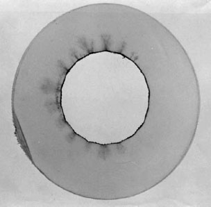
FIGURE 19.3 Vented fan trees growing from high electrical stress points in a HMWPE cable with taped strand shielding and a staining antioxidant. Photo by W. A. Thue.
19.3.1.4 Methods to Minimize Water Treeing
The most effective, if not economic, method to avoid the formation of water trees is to keep the insulation absolutely dry. This can be accomplished with an impervious metallic sheath such as lead, copper, or aluminum. Cables with these sheaths have been in service for over 40 years with no known deterioration. Of course, the problem is to keep the metal from corroding or being damaged mechanically. (This concern also applies to paper-insulated cables!)
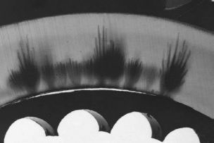
FIGURE 19.4 Vented water trees growing from a loose extruded strand shield in a 175-mil wall of XLPE cable.
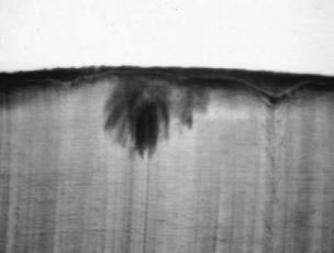
FIGURE 19.5 Water trees growing from taped insulation shield. Photo by W. A. Thue.
Other possible deterrents to water tree formation include:
1. Smooth electrical interfaces at the shields—especially at the conductor shield where the electrical stresses are the highest
2. Tightly bonded insulation shields that must be removed mechanically
3. Semiconducting compounds with small amounts of ionic impurities. It has been shown that ions from the shields are concentrated at water tree sites in the insulation
4. Solid conductors
5. Strand blocking
6. Internal pressure, such as nitrogen, to keep out moisture
7. Reduction or elimination of voids and contaminants
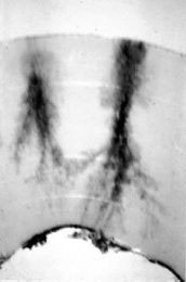
FIGURE 19.6 Two large water trees across a 220-mil HMWPE cable made with staining antioxidant. (Note that there is no electrical failure showing that even these water trees are capable of holding line voltage.) Photo by W. A. Thue.
19.3.2 INTRODUCTION TO ACCELERATED TESTING
Over the years, there has been tremendous effort given to understanding water trees because of their influence on the life of extruded dielectric cables with the subsequent loss of life [15–18]. Tests in laboratories can be separated into several methods:
1. Electrical properties of material specimens
2. Miniature cable evaluations
3. Typical full sized cables—usually 1/0 AWG, 175-mil wall cable
4. Actual cable construction being considered
The testing of specimens:
1. Testing of samples is the least expensive and is best suited for screening purposes. Here there are no complicating problems of extrusion and other manufacturing conditions.
2. Miniature cables are the least expensive way to introduce the manufacturing and processing concerns, but have not shown to be in good correlation with full sized cables.
3. The 1/0 AWG, 175-mil cable has become the most commonly used full sized cable because it is a very common size among the utilities in North America, and because of its modest cost of production. Manufacturing and processing are factored into the results. These tests are still very costly with a typical AEIC Qualification Test requiring $50,000 or more and 12 months to accomplish.
4. Tests on the actual cable under consideration are even more costly than that for the 1/0 cable described above.
Electrical trees in extruded dielectric cables are the result of internal electrical discharges that decompose the organic materials. No moisture is needed for this process. Overvoltages are required and may occur because of imperfections in the structure that cause high, localized electrical stress. Stress enhancement calculations from the tip of a sharp conductive electrode having a radius of 2.5 microns vary from 240 to 480 times the average stress at that point [8]. Since a typical distribution cable has an average stress of about 35 volts per mil, the resultant stress level is considerable. Other overvoltage situations include lightning strokes, switching surges, and test voltages.
Several mechanisms have been proposed to explain the initiation of electrical trees. Each requires a very high electrical stress to attain the energy level that would be required. Some of the possibilities are as follows:
1. Localized heating and thermal decomposition
2. Mechanical damage due to high electrical stress
3. Fatigue cracking from polarity changes
4. Small voids
5. Air inclusions around contaminants
6. Electron injection
Partial discharges that decompose the organic material in insulations are generally considered the common factor in the formation of electrical trees. The intrinsic electrical strength of the commonly used material is many times higher than the electrical stresses that are encountered in actual service. How can these excellent materials fail at such low stresses? The presence of internal voids, contaminants, and external stress points leads to electrical stress enhancements that are sufficiently high to originate water trees.
Impulses, surges, and DC stresses seem to create hollow channels through the insulation that we know as electrical trees. When seen in wafers, electrical trees are distinct and opaque. The waters usually do not have to be stained those trees to see them, but staining is certainly a recommended practice. Electrical trees require high stress but not water, and they grow relatively fast—in minutes to hours. Examples of electrical trees are shown in Figures 19.7 through 19.9.
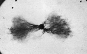
FIGURE 19.7 Bow tie growing from a contaminant (hence nonvented). Photo by W. A. Thue.
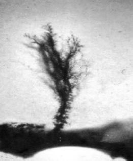
FIGURE 19.8 Bush tree growing from a shield (hence vented). Photo by W. A. Thue.
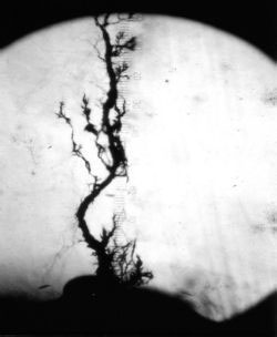
FIGURE 19.9 Electrical tree growing from a contaminant on conductor shield. Courtesy of University of Wisconsin–Madison.
19.5 COMBINATIONS OF ELECTRICAL AND WATER TREES
“Under certain conditions, combinations of electrical and electrochemical trees can occur” said John Densley in his 1979 paper [11]. Thirty years have passed and yet this combination seems to have been overlooked by many people in their attempt to have only two categories of trees in extruded dielectrics.
The fact is that field samples have shown this condition for an equal number of years. They generally appear as water trees with small sections of dark, obvious electrical trees in the branch. Another form of this condition is found when installed cables are tested after service aging using diagnostic testing procedures. Wafers show the presence of a large, vented water tree with an electrical tree growing from the leading edge.
The importance of these observations is that they most likely show the transition of water trees (benign as they may be) to partial electrical trees—where the end of life of the cable is at hand. This may explain why water trees are deleterious to extruded dielectric cables.
One concept of the mechanism where water trees are converted to sections having electrical trees is referred to as trapped space charges. Electrons with high energy levels are used to crosslink polyethylene in what is called radiation curing. Cross-linkable polyethylene is applied to a conductor, the conductor is grounded, and electrons are beamed through the dielectric cable with sufficient energy that they reach the conductor.
If the energy level is not high enough to penetrate the entire wall, electrons may be trapped in the insulation. Likely sites for such trapping are oxidized material (such as are found in water trees in service-aged cables). In a new cable, these trapped electrons can stay in a dormant condition for months. The mechanical effects of installation or increase in temperature can give these electrons sufficient energy to start moving. As they move toward the metallic member (conductor or shield), these electrons drill a channel through the insulation. This is not called an electrical tree, but it has many of the same characteristics. If the electron is trapped near the conductor for instance, the channel only extends from the site to the conductor—not in both directions.
Trapped charges can affect installed cables. A high-energy lightning stroke can deposit electrons at sites in the insulation wall—just as described previously. Again, these electrons may stay dormant until some additional energy is applied such as a temperature increase. When the energy level is sufficiently high, the electron will move. It travels may be to one of the metallic components or merely to one of the adjacent sites such as a void. The result of this action is to breech a portion of the good insulating wall. Another lightning stroke may do additional damage or the owner might use high-energy direct voltage or capacitor discharge equipment on the cable. All of these sources can provide electron entrapment with subsequent additional deterioration of the insulating wall.
It is very important to know that water trees can be the sites for the trapped charges. This means that after being in service for a period of time, cables having water trees are more prone to trapped charges because the sites for this entrapment have been developed. These sites may be in the microvoids or in the somewhat deteriorated insulation between those microvoids.
These combination water and electrical trees have also been seen on service-aged cables that have been tested with modestly elevated voltages during diagnostic evaluations. A partial discharge site may be located with or without a failure in the field. A typical wafer examination of this area shows extensive water treeing patterns; however, one will have an electrical tree growing from the water tree. The opinion is that a partial discharge test will locate a water tree, but during the test, an electrical tree will begin to grow and hence be detected by the test.
Figure 19.10 shows a tree site with both water and electrical trees. Note that there is one water tree from a shield at the left of the picture and that the electrical tree has grown from the same site as the earlier water tree.
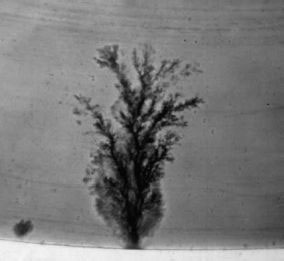
FIGURE 19.10 Combination of water and electrical trees. Courtesy of University of Wisconsin–Madison.
Another combination of water and electrical trees is shown in Figure 19.11.
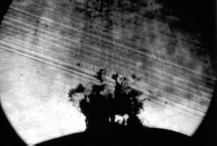
FIGURE 19.11 Water tree and electrical tree. Photo by W. A. Thue.
Another combination of electrical and water trees at the same site is shown in Figure 19.12. Note that the water tree has burned sections indicating the transition from a water tree to an electrical tree.
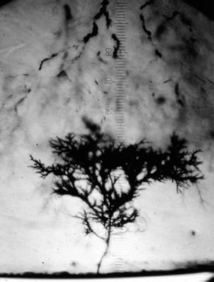
FIGURE 19.12 Electrical tree in a water tree. Photo by W. A. Thue.
An example of a field failure pattern may help illustrate this phenomenon. Service failures of extruded dielectric cables peak during lightning seasons but, even with the sophisticated lightning counter facilities now available, the actual field failure seldom occurs just as the lightning strikes in the vicinity of the cable. The failure is delayed by days or weeks, but the failure location and the lightning strike point are very close. It seems highly likely that the lightning strike converted a water-treed area to a partial electrical tree that continued to grow until the insulation was no longer capable of serving its function under normal operating voltage.
Conversion of a water tree to an electrical tree seems to be an important factor. This occurs by the formation of an electrical tree from the tip of a water tree as well as inside a water tree where a portion of the “branch” is an electrical tree that has not progressed sufficiently that it has caused complete electrical breakdown. This conversion can certainly be accelerated by the effect of trapped charges.
Treeing was considered to be a laboratory “trick” until the 1970s. Some of the earliest work was done by Simplex Wire & Cable. Hunt, Pratt, Ware, Kitchin, and others [19–21] reported on the work done with one needle embedded in small slabs of polyethylene beginning in 1956. From this work, they developed the first commercial tree retardant HMWPE insulation. They reported in 1958 that moisture was an inhibitor to tree growth. What was not known at that time was that they were looking only at electrical trees. They confidently predicted in 1958 that “HMWPE may last more than 40 years in water at operating stress up to 45 volts per mil.” They were not aware of the existence of water trees as we now understand them nor did they repeat that statement made in that first paper that “…at the end of 40 years, half the lengths of cable will have failed.”
Other researchers in that same time period began using two embedded needles. See Figure 19.13 for the test geometry of a double needle test. The “standard defect” consists of a specially sharpened sewing needle that is inserted into one of the small faces of a block of compression molded plastic that is 1” × 1” × 0.25” and the point of the sharpened needle is 0.5” away from an ordinary (dull) needle. These needles are inserted under carefully controlled annealing conditions. McMahon and Perkins came up with similar conclusions and reported in 1960 that “corona life of a specimen of HMWPE in air is a strong function of humidity. A relative humidity of 95 to 100% gives approximately 15 times longer life than dry air.” They were also only looking at electrical trees.
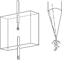
FIGURE 19.13 Double needle test specimen. Courtesy of University of Wisconsin–Madison.
After the reported findings of Lawson and Vahlstrom [5,6] and the reports by Tabata et al. in 1972 of “sulfide trees” [7] in cables removed from the field, laboratory work moved toward wet testing of insulating materials such as the test developed by McMahon and Perkins. Specimen testing for water treeing is generally done in this “pie plate.” This is a compression molded, dish-shaped specimen that has 24 conical depressions molded into the bottom (see Figure 19.14). The specimen dish is placed into a grounded bath that contains an electrolyte—usually made by adding 0.01 N NaCl in distilled water. A platinum wire connects a power supply to the upper portion of the dish. From 2 to 8 kV AC is applied. A low-density polyethylene (LDPE) specimen will develop water trees at the tips of the cones from 120 to 240 μm in length in 24 hours at 5 kV. The length of these water trees is then measured.
Figure 19.15 is a photograph of a water tree growing from one of the indents in a pie plate.
By 1975, the Association of Edison Illuminating Companies (AEIC) had developed an accelerated water-treeing test (AWTT) on actual full sized cable samples placed in water-filled pipes. This test is part of the qualification testing requirement to meet AEIC specifications.
Tank tests were developed at the Marshall, Texas, facility of Alcoa by Lyle and Kirkland in 1981 [9]. Testing in tanks has continued for more than 20 years at that facility even with all of the changes in names that have occurred!
The test protocol is based on samples of full sized cables formed into coils and placed in tanks filled with water. Water is also kept in the strands of the 30-feet long cable samples. Voltage is supplied continuously while the current flows for 8 hours every day. Twelve samples are energized until one fails. That failed sample is replaced with a dummy cable while the remaining active samples are energized until the next one fails. After eight of the twelve samples have failed, the remaining four samples are broken down with AC step-rise voltage application.
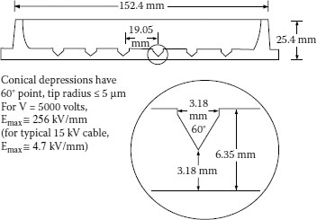
FIGURE 19.14 Water tree test specimen—“pie plate”. Courtesy of University of Wisconsin–Madison.
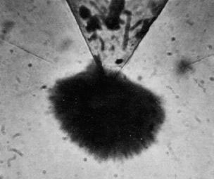
FIGURE 19.15 Water tree from a pie plate indent. Courtesy of University of Wisconsin–Madison.
In the original work, nine different voltage stress/temperature combinations were applied: 60°C, 75°C and 90°C; two, three, and four times rated voltage to ground. The results of these nine conditions are mathematically analyzed to obtain a model of a life curve that is used to demonstrate life at other stress/voltage levels such as would be found in typical operation.
This time-to-failure accelerated laboratory aging information that is developed is used to predict the life of that cable construction and processing. In this manner, other insulations, stress relief materials, and constructions can be compared directly. The significant advantage of the method is that twelve samples give a much higher confidence level in the results than a smaller number and that time to breakdown is more nearly like real life than if an AC step breakdown is used.
19.7 TECHNICAL DISCUSSION OF TREEING
Treeing has been demonstrated as one of the most important factors involved in loss of life for medium voltage cables. Electrical trees are considered to be associated with the final cable failure and do not exist for a long period of time. Water trees are the slower growing variety. They can extend from one electrode to the other without a service failure. Once they have formed, water trees seem to be converted to electrical trees for part or all of their length by DC, surges, and impulses. Conclusions in recent research work show that treed cables that are subjected to DC, surges, or impulses have shorter life in service after that application than cables not subjected to those stresses.
There are several possible explanations for this “conversion” of a water tree to an electrical tree, but the more commonly accepted explanation is that charges are trapped in the insulation wall. When these trapped charges are disturbed by heat or mechanical motion, they can literally bore a hole through the insulation wall. A likely scenario is that the trapped charges bore a tunnel from one void or contaminant to the next one. The insulation between these voids may be in a deteriorated condition, thus speeding up the damage from the trapped charges. This continues until the wall has virtually been destroyed and the cable cannot hold even line voltage.
Inception of water trees is likely to be the result of voltage enhancements at voids, contaminants, or other imperfections in the cable. Another significant factor is that the presence of ionic impurities is especially deleterious to cables. At one time it was thought that the source of these ions was from ground water or the like. It is now established that the source of these impurities is often the materials in the cable—basically contaminants in the older semiconducting shield materials. Microscopically small “chunks” of sand make the insulation/shield interface another source of voltage enhancement. Growth or propagation of the water tree is apparently quite slow—several years in a well-made cable. Bow tie trees may stop propagating as they grow large enough to decrease the voltage stress at their extremities.
We know that voltage stress and temperature accelerate this propagation of water trees. XLPE and thermoplastic polyethylene are adversely affected by temperatures above about 75°C—as demonstrated by laboratory aging studies [10].
As briefly mentioned previously, there is only a small distinction between water and electrochemical trees that result from a “natural” staining of the interior or the voids. Pre-1970 HMWPE insulation was formulated with a staining antioxidant. These cables did not require any dying to see the trees. The change to nonstaining antioxidant around 1970 resulted in water trees that could not be seen unless the wafers were put in a dye solution. In the transition period, it was thought that possibly the staining antioxidant had caused the trees! The dying procedure is given at the end of this section.
Trees also exist and are visible in EPR insulated cable but they can only be seen at the surface of the cut. A similar dying procedure is used for EPR but the staining time must be increased considerably. There are also proprietary methods for staining EPR cable samples. Tree counts in EPR are lower than for the nonopaque types because of not being able to see down into the material, but they may be lower also because they simply do not tree the same way as XLPE cables.
Trees positively initiate at defects within the cable such as at discontinuities between the interfaces of the insulation and the two shields, and at voids and contaminants—metal particles, threads, oxidized bits of insulation (ambers), and even at chunks of undispersed antioxidant.
Trees that have one of their points of origin at the insulation/shield interface are called “vented” trees. They always show up as the dangerous trees as compared with the ones that stay completely within the wall of insulation—the nonvented tree. The probable explanation here is that pressure can build up within the nonvented tree, and this would suppress the partial discharge.
19.8 METHYLENE BLUE DYING TECHNIQUE
Prepare the specimen for dying by removing the conductor to obtain a sufficient length of insulation for examination. Using a very sharp tool (lathe, microtome, or trimmer), make slices of the insulation that are about 25 mils thick.
In a 500 ml beaker with watch glass cover, place:
1. 250 ml distilled water
2. 0.50 gm methylene blue
3. 8 ml concentrated aqueous ammonia
Heat to boiling with continuous stirring. Use a fume hood or other adequate ventilation. Place the specimens to be stained in the solution using a wire for installation and removal. Remove specimens from hot solution from time to time to be certain that the staining is neither too light nor too dark. The time will be dependent on the thickness of the sample as well as the type of insulation.
When the specimens are adequately stained, remove from the hot solution, rinse in hot water, and wipe dry.
A thin film of oil on the surface of the sample makes observation with a microscope much less confused by scratches. A 30-power lens should be used for initial observation purposes.
Record the number of bow tie trees (originating within the insulation wall) and the vented trees (originating from the conductor or insulation shields) that are greater than 2 mils in length. The length for bow ties shall be the peak-to-peak length. For vented trees, the length shall be the maximum distance from the surface of the shield to the tip of the tree. List the numbers in size ranges and by type.
19.9 OBSERVATION IN SILICONE OIL
An excellent method of observing several inches of insulation at one time is to place a 1-foot sample on the insulated cable (the semiconducting insulation shield must be removed!) in a glass beaker with silicone oil that has been heated to about 130°C. At about this temperature, all of the crystallinity is gone and the insulation becomes quite clear. The surface of the conductor shield can be observed for smoothness. Voids or contaminants in the insulation wall can be readily seen. Note: “voids” can be created during the test by moisture in the insulation resulting from service conditions. Such “voids” will grow in size during the observation period so that they are obviously caused by the moisture. A way to eliminate this possibility is to dry the field sample in an oven prior to the observation.
1. Rayner, E. H., 1912, British JIEE 49, p. 3.
2. Whitehead, S., 1932, “Breakdown of Solid Dielectrics”, Earnest Bend, London.
3. Tykociner, J. T., Brown, H. A. and Paine, E. B., 1933, University of Illinois Engineering Experiment Station, Bulletins 259 and 260.
4. Kreuger, F. H., 1965, “Discharge Detection in High Voltage Equipment”, American Elsevier Publishing Co., New York.
5. Vahlstrom, W., Jr., 27 September–1 October 1972, “Investigation of Insulation Deterioration in 15 and 22 kV Polyethylene Cables Removed from Service – Part I”, IEEE Underground Distribution Conference, Detroit, MI.
6. Lawson, J. H. and Vahlstrom, W., Jr., 27 September–1 October 1972, “Investigation of Insulation Deterioration in 15 and 22 kV Polyethylene Cables Removed from Service – Part II”, IEEE Underground Distribution Conference, Detroit, MI.
7. Tabata, T., Nagai, H., Fukuda, T. and Iwata, Z., 18–23 July 1971, “Sulfide Attack and Treeing of Polyethylene Insulated Cables – Cause and Prevention”, IEEE Summer Power Meeting.
8. “Treeing Update”, Kabelitems, Part 1, Vol. 150, pp. 8–9, 1977.
9. “Treeing Update”, Kabelitems, Parts I, II, III, Vols. 150, 151 and 152, Union Carbide, 1977. (There are 162 references in these three volumes.)
10. “Electrochemical Treeing in Cable”, EPRI EL-647, Project 133, January 1978.
11. Densley, R. J., June 1979, “An Investigation into Growth of Electrical Trees in XLPE Cable Insulation”, IEEE Vol. EI-14 (No. 3).
12. Sletbak, J., August 1979, “A Theory of Water Tree Initiation and Growth,” IEEE Vol. PAS-98, #4.
13. Lyle, R. and Thue, W. A., 1983, “The Origin & Effect of Small Discontinuities in Polyethylene Insulated URD Cables”, IEEE 83 WM 002-3.
14. Nunes, S. L. and Shaw, M. T., December 1980, “Water Treeing in Polyethylene – A Review of Mechanisms”, IEEE Vol. EI-15 #6.
15. Lyle, R. and Kirkland, J. W., “An Accelerated Life Test for Evaluating Power Cable Insulation”, IEEE 81 WM 115-5.
16. Sletbak, J. and Ildstad, E., “The Effect of Service and Test Conditions on Water Tree Growth”, IEEE 83 WM 003-1.
17. Lyle, R., 1986, “Effect of Testing Parameters on the Outcome of the Accelerated Cable Life Test”, IEEE 86 T&D 577-1.
18. Walton, M. D., Smith, J. T. III, Bernstein, B. S. and Thue, W. A., “Accelerated Aging of Extruded Dielectric Power Cables Parts I, II, III”, IEEE Trans. PD Vol. 7, April, 1992 and 93 SM 559-5, 1992 and 1993.
19. Hunt, G. H., Koulopoulos, M. J., and Ware, P. H., April 1958, “Dielectric Strength and Voltage Life of Polyethylene Part III”, AIEE Transactions, Vol. 77, pp. 25–28.
20. Kitchin, D. W. and Pratt, O. S., June 1958, “Treeing in Polyethylene as a Prelude to Breakdown”, AIEE Transactions, Part III, Vol. 77, pp. 180–186.
21. Kitchin, D. W. and Pratt, O. S., June 1962, “An Accelerated Screening Test for Polyethylene High Voltage Insulation”, AIEE Transactions, Pt III, Vol. 81, pp. 112–121.
22. McMahon, E. J. and Perkins, J. R., 1963, “Volume Discharges and Treeing – A Primer”, 5th Electrical Insulation Conference on Materials and applications.