
CONTENTS
4.7 Cable Calculation Constants
4.7.1 Cable Insulation Resistance
4.7.2 Volume Insulation Resistance
4.9 Dielectric Loss in Cable Insulation
4.12 Charging Current for Alternating Current Operation
4.13 Cable Inductive Reactance
4.13.1 Cable Inductive Reactance at Higher Frequencies
4.14 Mutual Inductance in Cables
4.15 Cable Conductor Impedance
4.18.1 Voltage Stress in Cables
4.19 Review of Electrical Terms
4.19.6 Inductance in Multiconductor Cables
4.19.7 Mutual Inductance in Cables
4.19.8 Inductance in Coaxial Cables
4.21.1 Inductive Reactance Is Calculated From
4.21.2 Capacitive Reactance is Calculated From
4.24 Power Factor in Power Engineering
The rating, or voltage class, of a cable is based on the phase-to-phase voltage of the system even though it is in a single- or three-phase circuit. For example, a 15 kV rated cable (or a higher value) must be specified on a system that operates at 7,200 or 7,620 V to ground on a grounded wye 12,500 or 13,200 V system. This is based on the fact that the phase-to-phase voltage on a wye system is 1.732 (the square root of 3) times the phase-to-ground voltage. Another example is that a cable for operation at 14.4 kV to ground must be rated at 25 kV or higher since 14.4 times 1.732 is 24.94 kV (Figure 4.1).
The wye systems described above are usually protected by fuses or fast-acting relays. This is generally known as the 100% voltage level and was previously known as a “grounded” circuit. Additional insulation thickness is required for systems that are not grounded, such as found in some delta systems, impedance or resistance grounded systems, or systems that have slow-acting isolation schemes. The following voltage levels are found in AEIC specifications [1] and many other technical documents.
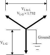
FIGURE 4.1 Voltage rating.
Cables in this category may be applied where the system is provided with relay protection such that ground faults will be cleared as rapidly as possible, but in any case within 1 minute. While these cables are applicable to the great majority of cable installations that are on grounded systems, they may be used also on other systems for which the application of cables is acceptable, provided the above clearing requirements are met in completely de-energizing the faulted section.
[Editor’s note: There have been incidents where devices designed to quickly de-energize a circuit have been installed but not utilized. Such reluctance to deenergize quickly can result in serious problems for those cable systems.]
This insulation level corresponds to that formerly designated for “ungrounded” systems. Cables in this category may be applied in those situations where the clearing time requirements of the 100 percent category cannot be met, and yet there is adequate assurance that the faulted section will be de-energized in a time not exceeding 1 hour. Also, they may be used when additional insulation strength over the 100 percent level category is desirable.
Cables in this category should be applied on systems where the time required to de-energize a section is indefinite. Their use is recommended also for resonant grounded systems. Consult the (cable) manufacturer for insulation thickness.
Cables are not recommended for use on systems where the ratio of the zero to positive phase reactance of the system at the point of cable application lies between −1 and −40 since excessively high voltages may be encountered in the case of ground faults.
Low-voltage cable ratings follow the same general rules as for the medium-voltage cables previously discussed in that they are also based on phase-to-phase operation. The practical point here is that a cable that operates at say 480 V from phase-to-ground on a grounded wye system requires an insulation thickness applicable to 480 × 1.732 or 831 V phase-to-phase. This, of course, means that a 1,000 V level of insulation thickness should be selected.
There are no categories for low-voltage cables that address the 100, 133, and 173 percent levels. One of the main reasons for the thickness of insulation walls for these low-voltage cables in the applicable standards is that mechanical requirements of these cables dictate the insulation thickness. As a practical matter, all these cables are overinsulated for the actual voltages involved.
4.7 CABLE CALCULATION CONSTANTS
There are four main calculation constants that affect the functioning of a cable on an electric system: resistance, capacitance, inductance, and conductance. Conductor resistance has been addressed in Chapter 3.
4.7.1 CABLE INSULATION RESISTANCE
The resistance to flow of a direct current (DC) through an insulating material (dielectric) is known as insulation resistance. There are two possible paths for current to flow when measuring insulation resistance:
1. Through the body of the insulation (volume insulation resistance)
2. Over the surface of the insulation system (surface resistivity)
4.7.2 VOLUME INSULATION RESISTANCE
The volume insulation resistance of a cable is the DC resistance offered by the insulation to an impressed DC voltage tending to produce a radial flow of leakage through that insulation material. This is expressed as a resistance value in megohms for 1,000 feet of cable for a given conductor diameter and insulation thickness. Note that this is for 1,000 feet, not per 1,000 feet! This means that the longer the cable, the lower the resistance value that is read on a meter since there are more parallel paths for current to flow to ground. The basic formula for a single conductor cable of cylindrical geometry is:
(4.1) |
where
IR = megohms for 1,000 feet of cable
K = insulation resistance constant
D = diameter over the insulation (under the insulation shield)
d = diameter under the insulation (over the conductor shield). Note: Both D and d must be expressed in the same units.
In order to measure the insulation resistance of a cable, the insulation must either be enclosed in a grounded metallic shield or immersed in water. Resistance measurements are greatly influenced by temperature—the higher the temperature, the lower the insulation resistance. The cable manufacturer should be contacted for the temperature correction factor for the specific insulation. Equation 4.1 is based on values at 60°F.
TABLE 4.1
Insulation Resistance
Insulation |
ICEA Minimum |
Typical |
HMWPE |
50,000 |
1,000,000 |
XLPE and EPR, 600 V |
10,000 |
100,000 |
XLPE and EPR, Med. Voltage |
20,000 |
200,000 |
PVC at 60°C |
2,000 |
20,000 |
PVC at 75°C |
500 |
5,000 |
The values shown in Table 4.1 are also based on this temperature. The ICEA minimum requirements of IR (sometimes referred to as “guaranteed values”) are shown as well to represent values that may be measured in the field. The actual values of IR that would be read in a laboratory environment are many times higher than these “minimum” values and approach the “typical” values shown in Table 4.1.
One of our contributors often stated that “all cables have two ends.” These terminations or ends, when voltage is applied to the conductor, can have current flow over the surface of that material. This current adds to the current that flows through the volume of insulation, which lowers the apparent volume insulation resistance unless measures are taken to eliminate that current flow while the measurements described above are being made. This same situation can occur when samples of insulation are measured in the laboratory. A “guard” circuit is used to eliminate the surface leakage currents from the volume resistivity measurement.
The current generated when a cable is energized from a DC source is somewhat complicated because there are several currents that combine to form the total leakage current. These currents are: IL = leakage current, IG = charging current, IA = absorption current.
The DC charging current behaves differently than the alternating current (AC) in that the DC value rises dramatically during the initial inrush. It decreases rather quickly with time, however. The magnitude of the charging and absorption currents is not usually very important except that it may distort the true leakage current reading. The longer the length and the larger the cable size, the greater the inrush current and the longer it will take for the current to recede. This initial current decays exponentially to zero in accordance with the following equation:
(4.2) |
where
IG = charging current in microamperes per 1,000 feet
E = voltage of conductor to ground in volts
R = DC resistance of cable in megohms for 1,000 feet
ε = base of natural logarithm (2.718281…)
t = time in seconds
C = capacitance of circuit in microfarads per 1,000 feet
The absorption current is caused by the polarization and accumulation of electric charges that accumulate in a dielectric under applied voltage stress. The absorption current normally is relatively small and decreases with time. Absorption current represents the stored energy in the dielectric. Short-term grounding of the conductor may not give a sufficient amount of time for that energy to flow to ground. Removing the ground too quickly can result in the charge reappearing as a voltage on the conductor. The general rule is that the ground should be left on for one to four times the time period during which the DC source was applied to the cable. The absorption current is:
(4.3) |
where
IA = absorption current in microamperes per 1,000 feet
V = incremental voltage change in volts
C = capacitance in microfarads per 1,000 feet
t = time in seconds
A and B are constants depending on the insulation.
A and B are constants that differ with the specific cable since they are dependent on the type and condition of the insulation. They generally vary in a range that limits the absorption current to a small value compared to the other DC currents. This current decays rather rapidly when a steady-state voltage level is reached.
The current that is of most importance is the leakage or conduction current. The leakage current is dependent on the applied voltage, the insulation resistance of the cable insulation, and any other series resistance in the circuit. This value becomes very difficult to read accurately at high voltages because of the possibility of end leakage currents as well as the transient currents. The formula for leakage current is:
(4.4) |
where
IL = leakage current in microamperes per 1,000 feet
E = voltage between conductor and ground in volts
RI = insulation resistance in megohms for 1,000 feet.
The total current is:
(4.5) |
The voltage must be raised slowly and gradually because of the rapid rise of IG and IA with time. Also, since both of these values are a function of cable length, the longer the cable length, the slower the rise of voltage allowable. Equation 4.5 demonstrates the reason for taking a reading of leakage current after a specified period of time so that the actual leakage current can be determined.
Dielectric constant, relative permittivity, and specific inductive capacitance all mean the same. They are the ratio of the absolute permittivity of a given dielectric material to the absolute permittivity of free space (vacuum). The symbol for permittivity is ε (epsilon). To put this in another way, these terms refer to the ratio of the capacitance of a given thickness of insulation to the capacitance of the same capacitor insulated with vacuum. (This is occasionally referred to as air rather than vacuum, but the actual dielectric constant of air is 1.0006). Since the calculations are usually not taken out to more than two decimal points, it is practical to use air for comparison. The value of permittivity, dielectric constant, and specific inductive capacitance (SIC) are expressed simply as a number since the dielectric constant of a vacuum is taken as 1.0000.
4.9 DIELECTRIC LOSS IN CABLE INSULATION
The losses in the insulation of a cable may be calculated from the following equation:
(4.6) |
where
W = watts loss per foot of cable
ε = dielectric constant of the insulation
f = frequency in hertz
C = capacitance of the insulation per foot
n = number of conductors in the cable
e = voltage conductor to neutral in kilovolts
FP = power factor of the insulation as a decimal.
The property of a cable system that permits the conductor to maintain a potential across the insulation is known as capacitance. Its value is dependent on the permittivity (dielectric constant) of the insulation and the diameters of the conductor and the insulation. A cable is a distributed capacitor. Capacitance is important in cable applications since charging current is proportional to the capacitance as well as to the system voltage and frequency. Since the charging current is also proportional to length, the required current will increase with cable length.
The capacitance of a single conductor cable having an overall grounded shield or immersed in water to provide a ground plane may be calculated from the following formula:
(4.7) |
where
C = capacitance in microfarads per 1,000 feet
ε = permittivity of the insulating material. Permittivity (ε, epsilon), dielectric constant (K), and SIC terms are used interchangeably. The term permittivity is preferred. See Table 4.2.
D = diameter over the insulation (under the insulation shield)
d = diameter under the insulation (over the conductor shield). Note: Both D and d must be expressed in the same units.
In single conductor, low-voltage cables where there is no semiconducting layer over the conductor, a correction factor must be used to compensate for the irregularities of the stranded conductor surface as shown in Table 4.3. This measurement is based on having an insulation shield/sheath or a conducting surface over the insulation.
TABLE 4.2
Permittivity, Dielectric Constant, and SIC (All Mean the Same Thing)
Material |
Range |
Typical |
Butyl Rubber |
3.0–4.5 |
3.5 |
EPR |
2.5–3.5 |
3.0 or 3.5 |
Halar (ETFE) |
2.5 |
2.5 |
HMWPE2 |
1–2.6 |
2.2 |
Hypalon |
7–10 |
8 |
Kynar (PVDF) |
6–12 |
10 |
Mica |
6.9 |
6.9 |
Neoprene |
9–10 |
9.5 |
Paper, impregnated |
3.3–3.7 |
3.5 |
Polyester (Mylar) |
3.3–3.8 |
3.5 |
Polyvinyl chloride (PVC) |
3.1–10 |
6.0 |
Rubber-GRS or Natural |
2.7–7 |
3.5 |
Silicone Rubber |
2.9–6 |
4.0 |
Teflon (FEP, TFE) |
2.1 |
2.1 |
Tefzel (EFTE) |
2.6 |
2.6 |
TR-XLPE2. |
1–2.6 |
2.3 |
XLPE2. |
1–2.6 |
2.3 |
XLPE, filled |
3.5–6.0 |
4.5 |
Varnished Cambric |
4.0–6.0 |
5.0 |
TABLE 4.3
Correction Factors for Irregularities
Number of Strands |
Factor k |
1 (solid) |
1.0 |
7 |
0.94 |
19 |
0.97 |
37 |
0.98 |
61 and 91 |
0.985 |
(4.8) |
The capacitive reactance of a cable is inversely dependent on the capacitance of the cable and the frequency at which it operates.
(4.9) |
where
Xc = ohms per foot
f = frequency in hertz
C = capacitance in picofarads per foot
4.12 CHARGING CURRENT FOR ALTERNATING CURRENT OPERATION
For a single conductor cable, the current may be calculated from the formula:
(4.10) |
where
IC = charging current in milliamperes per 1,000 feet
f = frequency in hertz
C = capacitance in picofarads per foot
E = voltage from conductor to neutral in kilovolts.
Other leakage currents are also present, but the capacitive current has the largest magnitude. In addition to this, the capacitive charging current flows as long as the system is energized. The resistive component of the charging current is also dependent on the same factors as the capacitive current and is given by the formula:
(4.11) |
where
IR = resistive component of the charging current
tan δ = dissipation factor of the insulation.
The tan δ of medium-voltage insulation, such as cross-linked polyethylene and ethylene propylene, has values that are generally below 0.02 so the resistive component of the charging current is only a small fraction of the total charging current. The tan δ is sometimes referred to as the insulation power factor since at small angles, these values are approximately equal. Since the capacitive charging current is 90° out of phase with the resistive charging current, the total charging current is generally given as the capacitive component and leads any resistive current flowing in the circuit by 90°. The result of these AC currents generated puts demands on the power required for test equipment.
4.13 CABLE INDUCTIVE REACTANCE
The inductive reactance of an electrical circuit is based on Faraday’s law. That law states that the induced voltage appearing in a circuit is proportional to the rate of change of the magnetic flux that links it. The inductance of an electrical circuit consisting of parallel conductors, such as a single-phase concentric neutral cable, may be calculated from the following equation:
(4.12) |
where
XL = ohms per 1,000 feet
S = distance from the center of the cable conductor to the center of the neutral
r = radius of the center conductor. S and r must be expressed in the same unit, such as inches.
The inductance of a multiconductor cable mainly depends on the thickness of the insulation over the conductor.
4.13.1 CABLE INDUCTIVE REACTANCE AT HIGHER FREQUENCIES
Since the inductive reactance of an insulated conductor is directly proportional to frequency, the inductive reactance is substantially increased in higher frequency applications. Conductors must be kept as close together as possible. Due to the severe increase in inductive reactance at high frequency, many applications will require using two conductors per phase to reduce the inductive reactance to approximately one-half of that of using one conductor per phase. A six-conductor installation should have the same phase conductors 180° apart.
4.14 MUTUAL INDUCTANCE IN CABLES
In single-conductor shielded or metallic-sheathed cables, current in the conductor will cause a voltage to be produced in the shield or sheath. If the shield or sheath forms part of a closed circuit, a current will flow. (Shield and sheath losses are described under Ampacity in Chapter 13).
The approximate mutual inductance between shields or sheaths is given by the following relation:
(4.13) |
where
Lm = henries to neutral per 1,000 feet
S = geometric mean spacing between cable centerlines in inches
rm = mean shield or sheath radius in inches. See Figure 4.2.
4.15 CABLE CONDUCTOR IMPEDANCE
Conductor impedance of a cable may be calculated from the following equation:
(4.14) |
where
Z = conductor impedance in ohms per 1,000 feet
RAC = AC resistance in ohms per 1,000 feet
XL = conductor reactance in ohms per 1,000 feet.
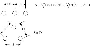
FIGURE 4.2 Geometric spacing.
Conductor impedance becomes an important factor when calculating voltage drop. Since the power factor angle of the load and impedance angle are usually different, the voltage drop calculation can be cumbersome. The following voltage drop equation can be used for a close approximation:
(4.15) |
where
VD = voltage drop from phase to neutral in volts
RAC = AC resistance of the length of cable in ohms
cos θ = power factor of the load
XL = inductive reactance of the length of cable in ohms.
The total cable reactance (X) is the vector sum of the capacitive reactance and the inductive reactance of the cable in ohms per foot.
(4.16) |
In cable engineering, the small amount of power consumed in the insulation (dielectric absorption) is due to losses. These losses are quite small in medium-voltage cables, but can become more significant in systems operating at 15 kV and above.
A small amount of power is consumed in an insulation due to its presence in an electric field and to the fact that no insulation is a perfect dielectric. In practical cables, there is a large amount of capacitive reactance and virtually no inductive reactance. Hence, the current leads the voltage by almost 90°. Since the cosine of 90° is zero, the cosine of an angle approaching 90° is very small. The actual value of such a small angle is almost equal to tan δ, hence cable engineers use this term to represent this “defect angle.”
In addition to the charging current flowing through the capacitive portion of the circuit, current also flows though the AC resistance portion of the circuit. This is the AC loss portion of the insulation circuit. The ratio of the AC resistance of the insulation to the capacitive reactance of the insulation is called the dissipation factor. This is equal to the tangent of the dissipation angle that is usually called tan δ. This tan δ is approximately equal to the power factor of the insulation, which is the cos θ of the complimentary angle.
In practical cable insulations and at 50 to 60 hertz, high insulation resistance and a comparatively large amount of capacitive reactance are present. There is virtually no inductive reactance. Hence, the current leads the voltage by almost 90°. Since the cosine of 90° is zero, the cosine of an angle approaching 90° is small and the dissipation factor (often referred to as power factor of the insulation) also is small. Typical values for insulation power factor are 0.005 to 0.02 or slightly higher for other materials.
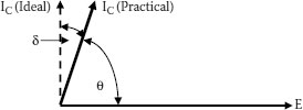
FIGURE 4.3 Cable insulation power factor or dissipation factor. Note: Tan δ is approximately equal to cos θ for the small angles involved.
Dissipation factor is used in cable engineering to determine the dielectric loss in the insulation, expressed as watts per foot of cable that is dissipated as heat. It is also used to some extent to describe the efficiency or perfection of the insulation as a dielectric. Hence, the term tan δ (delta) was chosen to represent the defect angle of the material (Figure 4.3).
The power dissipation per phase (dielectric loss, Wd) is a function of the voltage and the in-phase component of the current.
(4.17) |
The insulation parameters that determine the dielectric loss of a cable are the dielectric constant (permittivity, ε) and the dissipation factor (tan δ). The product of the permittivity and the dissipation factor is the dielectric loss factor (DLF). The lower the DLF, the better the insulation.
4.18.1 VOLTAGE STRESS IN CABLES
Voltage stress in shielded cable insulations with smooth, round conductors is defined as the electrical stress or voltage to which a unit thickness of insulation is subjected. The average stress in volts per mil is determined by dividing the voltage across the insulation by the insulation thickness in mils.
(4.18) |
where
Savg = average stress in volts per mil
V = voltage across the insulation
D = outside diameter of the insulation in mils
d = inside diameter of the insulation in mils.
The stress is not uniform throughout the wall. The stress at any point in the insulation wall can be calculated by the formula:
(4.19) |
where
S = stress in volts per mil at a point in the insulation r mils from the cylindrical axis.
The maximum stress occurs at the surface of the conductor shield.
(4.20) |
where the terms and units are the same as in Equations 4.16 through 4.18.
Although maximum and average stresses are important, dielectric strength is usually specified as the average stress at electrical breakdown. The dielectric strength of a material depends on the dimensions and the testing conditions, particularly the time duration of the test. A thin wall of material generally withstands a higher average stress before breaking down than a thicker wall.
These measurements are made in two ways: quick-rise or step-rise.
In the quick-rise method, the voltage applied to the insulation is raised at a uniform rate until the insulation breaks down. As an example, a rate of rise of 500 V per second is known as “quick-rise.”
In the “step-rise” method, the voltage is raised to a predetermined level and held at that level for an amount of time, such as 5 or 10 minutes at each level, until breakdown occurs. A relatively short time, say the 5 or 10 minutes described above, has the advantage of reaching breakdown in a shorter amount of total test time. In the real world, the time at a voltage level is much longer, so some cable engineers prefer a longer step time such as 30 minutes or 1 hour at each step. With the longer step times, the breakdown voltage is lower than with the quick-rise or short step time methods.
Because cable insulation is frequently subjected to lightning or switching surges, it is often desirable to know the impulse strength of the cable. Surges of “standard” wave shape, such as 8 seconds to reach 90% of crest value, and 40 microseconds to drop to one-half of crest value, are frequently used in the laboratory. The increasing voltages are applied to the insulation with several surges at a negative potential and then, at the same voltage level, the same number of surges are applied with positive pulses. The average stress in volts per mil is calculated from the crest voltage of the surge on which breakdown occurs.
4.19 REVIEW OF ELECTRICAL TERMS
These terms apply to all electrical engineering circuits. The actual application of these terms to cables is covered in Section 4.2 of this chapter. The more important equations are:
(4.21) |
(4.22) |
(4.23) |
(4.24) |
(4.25) |
(4.26) |
where
E = electromotive force in volts
I = current in amperes
R = resistance in ohms
Q = quantity in ohms
L = inductance in henries
C = capacitance in farads
P = power in watts
W = energy in joules
t = time in seconds.
(R) is the scalar property of an electric circuit that determines, for a given current, the rate at which electric energy is converted into heat or radiant energy. Its value is such that the product of the resistance and the square of the current gives the rate of conversion of energy.
In a direct-current circuit,
(4.27) |
and
(4.28) |
where
R = resistance in ohms
E = electromotive force in volts
I = current in amperes
P = power in watts.
(G) is the property of an electric circuit that determines, for a given electromotive force in the circuit or for a given potential difference between the terminals of a part of a circuit, the rate at which energy is converted into heat or radiant energy. This value is such that the product of the conductance and the square of the electromotive force, or potential difference, gives the rate of conversion of energy.
(4.29) |
where
P = power in watts
E = voltage, phase to ground, in kilovolts
G = conductance in mhos.
The unit of conductance is mho. Conductance is the reciprocal of resistance.
(4.30) |
where
G = conductance in mhos
R = resistance in ohms.
Conductivity (γ) of a material is the direct-current conductance between the opposite parallel faces of a portion of the material having unit length and unit cross section. It is the reciprocal of resistivity.
(4.31) |
where
G = conductance
a = area
l = length.
Volume resistivity of a material is the reciprocal of conductivity. The unit for volume resistivity is ρ (rho). It is the resistance of a section of material of unit length and unit cross section.
(4.32) |
where
R = resistance in ohms
ρ = rho, volume resistivity
a = area
l = length.
Unit L represents the scalar property of an electric circuit, or two neighboring circuits, which determines the electromotive force induced in one of the circuits by a change of current in either of them.
This is the property of an electric circuit that determines, for a given rate of change of current in the circuit, the electromotive force induced in the same circuit.
The unit of inductance is 1 henry. One henry is the self-inductance of a closed circuit in which an electromotive force of 1 V is produced when the electric current traversing the circuit varies uniformly at the rate of 1 ampere per second.
(4.33) |
where e1 and i1 are in the same circuit and L is the coefficient of self-inductance.
(Lm) is the common property of two associated electric circuits that determines, for a given rate of change of current in one of the circuits, the electromotive force induced in the other.
4.19.6 INDUCTANCE IN MULTICONDUCTOR CABLES
This is the same as any other arrangement of conductors and follows the following equation:
(4.34) |
where
GMD = geometric mean distance between conductors in inches
GMR = geometric radius of conductors in inches.
4.19.7 MUTUAL INDUCTANCE IN CABLES
In single conductor, metallic covered cables, current flowing in the conductor will produce an electromotive force in the sheath. If by any means the sheath forms a closed circuit, current will flow in the sheath based on the following equation:
(4.35) |
where
Lm = henries to neutral per 1,000 feet
rm = mean sheath radius in inches.
4.19.8 INDUCTANCE IN COAXIAL CABLES
In coaxial cables, three kinds of inductance must be taken into account: space inductance, inductance within the inner conductor, and inductance within the outer conductor. Above 50 kilohertz, only space inductance needs to be considered for results with less than 0.5% error. The equation for a coaxial cable with a tubular outer conductor becomes:
(4.36) |
where
Lf = inductance in henries per centimeter
r2 = inner radius of outer conductor in inches
r1 = radius of inner conductor in inches.
If the outer conductor is stranded or braided, the inductance is slightly higher.
This is the property of an electric system comprising insulated conductors and associated dielectric materials that determines, for a given time rate of change of potential difference between the conductors, the displacement currents in the system.
The unit of capacitance is the farad and it is that capacitance of a circuit whose potential difference will be raised 1 V by the addition of a charge of 1 coulomb.
The electrostatic capacitance of an insulated conductor 1 cm in length, in absolute units, is:
(4.37) |
where
C = capacitance
ε = dielectric constant of the insulating material
D = outer diameter of the insulation
d = inside diameter of the insulation.
In more common terms, the equation is:
(4.38) |
Reactance is the product of the sine of the angular phase difference between the current and potential difference times the ratio of the effective potential difference to the effective current because there is no source of power in the portion of the circuit under consideration. The total reactance of a circuit is the sum of the inductive and capacitive reactances.
4.21.1 INDUCTIVE REACTANCE IS CALCULATED FROM
(4.39) |
where
XL = inductive reactance in ohms/foot to neutral
f = frequency in hertz
L = inductance in henries/foot
and
(4.40) |
4.21.2 CAPACITIVE REACTANCE IS CALCULATED FROM
(4.41) |
where
XC = capacitive reactance in ohms/foot
C = capacitance in picofarads/foot.
The total reactance of a circuit is the sum of the inductive and capacitive reactances:
(4.42) |
Impedance is the ratio of the effective value of the potential difference between the terminals to the effective value of the current, there being no source of power in the portion of the circuit under consideration.
(4.43) |
(Y) is the reciprocal of impedance.
4.24 POWER FACTOR IN POWER ENGINEERING
Power factor, as used in power engineering, is not the same as “power factor” as used in cable engineering. In power engineering, power factor is the ratio of active power to apparent power. Apparent power (S) consists of two components; active (in-phase) power Pa, which does useful work, and reactive (out-of-phase) power Pr. Their geometric sum is the apparent power. Power factor is given by the equation:
(4.44) |
In power engineering, power factor is used, among other things, to determine the amount of useful work. In a motor, for example, resistance and a comparatively large amount of inductive reactance are present so that the current lags behind the voltage. If the power factor was 1.00 (unity) and no reactance was present, then with every 10 kVA all the current delivered to the motor (neglecting losses) would be in phase with the voltage and 10 kW would be applied as useful work. With a reactance present and a power factor of, say 0.80, only part of the current (8/10) is in phase with the voltage and only 8 kW would be delivered to the motor. The out-of-phase component of current increases the total current and results in increased heat loss.
Power factor may also be described as a measure of the relationship in time phase between the current and the voltage in any AC circuit. Practically, all AC circuits contain resistance, inductive reactance, and capacitive reactance. These characteristics determine how much the current leads or lags behind the voltage during each cycle. This is usually expressed in degrees by the use of a vector diagram. The angle between them indicates the amount of lead or lag. The cosine of that angle is called the power factor of that circuit. With only capacitive reactance, the current leads the voltage by 90°; with only inductive reactance, the current lags behind the voltage by 90°.
Cable systems with sealed metal sheaths, such as paper insulated lead covered (PILC) cables, can develop internal pressure or vacuum that may expand or collapse this sheath. These systems can develop this condition when the hydraulic pressure of the impregnate increases above the allowable “hoop stress” level of the sheath. PILC cables with viscous impregnates are generally limited to a height of about 32 feet in order to avoid damage to the sheath at the low point or excess vacuum at the high point of the system—usually at the terminations.
Most such systems are not sealed along their route. This results in the pressure being the same in the cable as in the splice when they are at the same elevation. The result of the same pressure can be dramatic since the diameter of the cable is considerably smaller than the diameter of the splice. Let us consider a cable having an internal sheath diameter of 3 inches and a splice with a 6 inch inner diameter of the sleeve. To keep this simple, the thickness of the sheath and sleeve will both be 0.1 inches. When a pressure of 10 psi is reached, the internal force trying to pull a 1 inch ring or “hoop” of the sheath or sleeve apart is three times the 10 psi or 30 pounds for two pieces of 0.1 square inch sections of lead—hence 150 psi. In the splice, the force is six times the 10 psi or 60 pounds. That translates to 300 psi, trying to swell the lead into a greater diameter. With the same thickness in both places, the force trying to pull the lead apart in the cable is 150 psi, but is 300 psi in the splice. This accounts for swollen splice sleeves. The unfortunate outcome is that if the sleeve increases in diameter, so does the force increase.
The allowable hoop stress for lead pipe (including cable sheath or splice sleeve) may be obtained by using the following formula:
(4.45) |
where
S = working stress (hoop stress) in pounds per square inch
D = inside diameter of sheath or sleeve in inches
P = internal fluid pressure in pounds per square inch
t = thickness of sheath or sleeve in inches.
The working value of S is obtained by assuming a safety factor based on ultimate strength. Values of S commonly used for lead sheaths and sleeve are: copper bearing lead: 125 pounds per square inch, arsenical lead: 175 pounds per square inch.
The practical solution to minimize lead sheath swelling in the splice is to use a stronger material such as arsenical lead and/or to increase the thickness of the splice sleeve.
1. Association of Edison Illuminating Companies, Specification CS8-07, 1st Ed., 2007, AEIC, P O Box 2641, Birmingham, AL, 35291-0992, USA.